BALDER, Vlaardingen Herring Lugger from 1912, scratch build scale 1:50 Plate-On-Frame

Hi peter,
Seeing these is it not better to just stamp these into the plastic with a small tube of the right size?
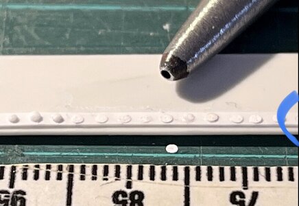
Thank you for your thoughts, Maarten. When making this experiment I also made a row of punches with the 1mm hollow pipe. Just not shown complete but a half of it is still visible on the right:
IMG_3816.jpeg
Then I also have to see what will be left after the parts are painted.
When I am back from holiday I will collect material to make a first frame on the 1:50 scale. To see whether it is all workable on that scale. The BALDER foundation documents also contain 1 old drawing of the 3 frames with watertight bulkheads. It has all the original dimensions, including the profiles used. I can then determine how I can make the rivets: melting, (glue) drops, punching (rondelles) or the resin sheets from America.
Perhaps a smaller hollow pipe, because in the old specifications the size of the rivets is stated as 7/8 and 5/8. Probably in Dutch thumbs, so I can use that for the resit sheets. The maker lists them as representative of 7/8" and 5/8". With different scales, usable ones must be no problem. Of course, it has to be nice in terms of costs with the expected numbers of rivets.
Also some further search, especially in aircraft model making. Because they also use flattened nails.
Regard, Peter
 
After 1.5 weeks of holiday, back on the iMac. Not with the 3D drawing, but with the preparation for making a test frames.
I can divide this preparations into 3 chapters.
1:
My starting point is the old drawing of the half-drawn 'Grootspant'/ Main frame. It is a scan of the old drawing from the yard "A. de Jong" and was included in the SZB files. It states that the width is 6.60 M. Not for the half, but for the entire frame.
Copied and mirrored that half frame in Photoshop:
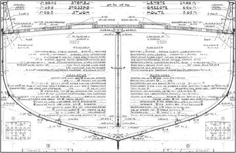
0026 Grootspant.jpg
6.60 meters is 13.2 cm in scale 1:50. I brought in the file the outside dimensions of the entire frame to 13.2 cm. Printed out it in also 13.2 cm wide. I can now use that print to make a mold.

2:
The drawing of the main frame also shows almost all the dimensions of the individual parts, such as the L-profiles for the frame but also the patterns of the rivets etc.
I also converted those dimensions from 1:50 and selected various Evergreen strips, profiles and sheet material. The order has gone out.

3:
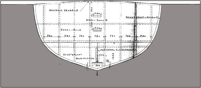
The files also include a drawing of the 3 frames with watertight bulkheads. I will also make the largest of these, frame 39, as a test, because then I will know whether the ordered sheet material can be used in terms of thickness/thinness:
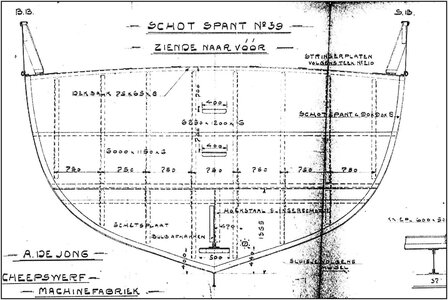
0027 Spant 39.jpg
Also a scan of an old drawing of yard " A. de Jong" and part of the SZB files.
There are no dimensions in that image.

Based on the line plan I can now derive dimensions:
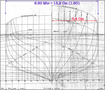
0028 Lijnenplan.jpg
This is the part with the drawn Station Lines.
Right, seen from the front: 9½, 9, 8, 7, 6 and 5
Left, seen from the back: 0, ½, 1, 2, 3, 4 and 5.
-In blue: The largest width is 6.6 meters, because of the size of the Grootspant = 13.2 cm. That are both Station Lines '5' drawn on the left and right side.
On the line plan of the longitudinal section I see that this Station Line '5' is drawn between frame '27' and '28'. For the time being I assume that both of these are the Grootspanten / Main Frames.
-In red: I can now measure half the frame '7' and that is 6.4 cm = 12.8 cm in its entirety.
I chose Station Line '7' because this Station Line is drawn on the aforementioned line plan just behind frame '39'.
Now I can bring the drawing of the frame '39' to the dimensions 12.8 cm and also print it out to that dimension.

To be sure, the main frame was placed on the image of the lines plan in Photoshop:
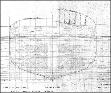
0029 Groot check.jpg
I placed the 2 drawings in 2 separate layers. And in Photoshop I can adjust the opacity per layer. Possibly not completely clear, but still placed to show the entire process.
It's a matter of check, check, double check.

Now just wait until the Evergreen material arrives.
In the meantime, continue with the 3D drawing.
Regards, Peter
 
Last edited:
I know how much fun it is to compare the drawings and measuring everything over and over again. Nice research, this will like Jim also said, pay of in the end.
That’s correct, Stephan. Hopefully like my Lee and BN: theory and practice must produce a results that will satisfy me.
Regards, Peter
 
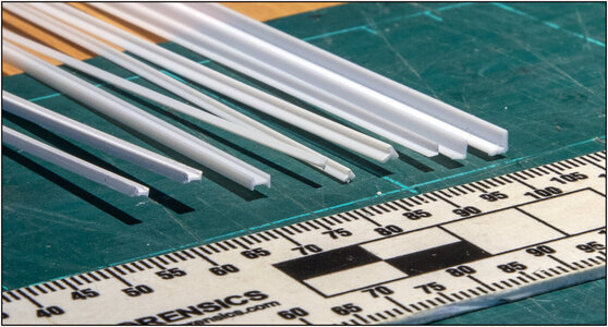
This morning my ordered Evergreen was delivered:
0030 Test-1.jpg
L, T and I profiles of 1.5x1.5, 2.0x2.0 and 2.5x2.5 mm. I can also cut the T and I-profiles to L-shape with different side sizes.

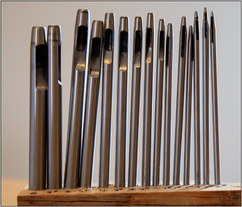
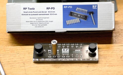
Because the 1mm punched rivets are too big, I started looking for smaller ones. Found this set of hole punches on Amazon that arrived yesterday:
0031 hollow.jpg
0.5 / 0.8 / 1.0 / 1.2 / 1.8 / 2 / and then per 1/2 mm increasing to 6 mm. I can build a model organ with those pipes, almost like the new organ of @RDN1954 Johan.:)

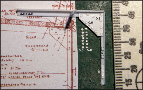
Started with a 1st test, the top right corner of the main frame:
0032 Test-2.jpg
I think it will come down to the 0.5 mm roundels. It will be a challenge, because they are just like fleas.
I punched them out of a thin white plastic cover.
I also tested punching directly on the material to get circles. But then I have to punch all the rivets on the parts before gluing. That's almost impossible.

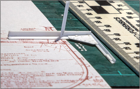
Seen from the side:
0033 Test-3.jpg
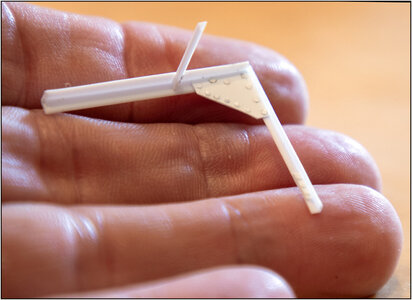
The stroke gives the roundels a bit of a curve. It's a matter of making sure that the right convex side is up and pressing it neatly into the glue.
Maybe I'll punch the roundels out of plain thin paper to get a slightly flatter appearance.
Do not pay attention to the connection of the profiles yet. I will edit that neatly during the next test of making the main truss.

Is it small ......... yes:
0034 Test-4.jpg
Is it a challenge........yes,
Will it be another project that will take a few years.........yes, probably.

PS: The resin rivet-sheets from the US still not delivered. But the request for import taxes was passed. I don't think they will be, because then it would be an expensive affair, given the amount of rivets required.
Kind regards, Peter
 
They are small - and I think you should go for the smaller with 0,5mm which are looking more in scale (unfortunately)
Thanks for your opinion, Uwe.
We can make the same discussion for rivets as for treenails. :)
Besides calculating it’s also the looks.
The rivets are in real 7/8 and 5/8 thumb. But that’s the shaft. For the 5/8 it’s 1,6 cm. In 1:50 it’s 0,32mm. With the riveted head on it, the 0,5 mm is in scale.
They were draw even smaller on the old drawing, but that’s not realistic.
Regards, Peter
 
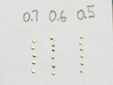
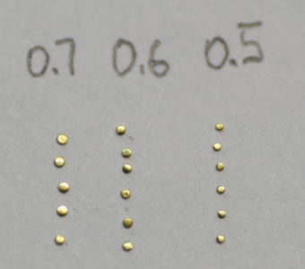
Hi Peter, below are the photos from today's experiment using the punch tool 0.5,0.6, and 0.7mm on the brass 0.13mm thickness. What do you think?

View attachment 395599

here is on the dark surface
View attachment 395601

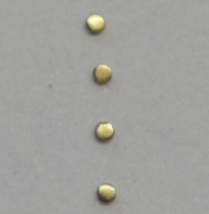
And MACRO 0.5mm

View attachment 395602
You also thanks for thinking with me, Jim.
Can you make a picture from beside? As show on the picture of the original Balder, the rivets are flattened or a little arch.
I have thin brass paper myself and will make a test.
Ps: what punch tools do you have? The Amazone set from $11,00 is from a …. mwa …. Quality ;) But I was glad I just found some 0,5 and 0,8.
 
Last edited:
Part 1 of testing: the main frame:
0035 Test-1 Grootspant.jpg
To bend the Evergeen profiles I turned on a electric kettle. Hold it against the warm side and they become flexible. Then quickly place the correct rounds on the drawings. At the bottom left of the horizontal profile is a piece of floor plate. I intend to provide the port side with floors, walls and skin plates. Starboard becomes 'open'.
The deck profile is 2.5x1.5 mm, for the hull 1.5x1.5 mm. The deck supports are ø 1.2 mm.
The rivets of the 0.5 mm stroke rounds were still just a bit too big for me. Did some tests and ended up with tips of wood glue (PVA). Because it is difficult to see on the white Evergreen, I mixed some gray glue in a small pot. Then you can see better what you are doing. The next step is to see what remains of the shape to be seen once the frame has been sprayed in color.

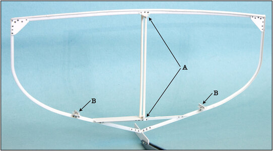
Also a point of attention for construction:
Parts of the four double L-profiles. To show there position, are also installed in the longitudinal direction of the hull.
For the 2 that I indicated with the arrows "B" it is no problem. These can be inserted through the frames and can then be secured.
I will have to think again about the one indicated by the arrows "A". The 2 round deck supports will be placed between the bottom and top edges of those profiles. I can only install the deck supports once the profiles are in place. I think it will mean that I place long pieces of profile in the 1st frame and that I have to build the next frames on top of that. It's just a matter of customizing the supports in advance. Let's think about it for a moment.........

So that's the advantage of some testing, you can immediately think a few steps ahead about the order of construction.
Because I also want to install the entire interior, I already intend to work from the front frame towards the back. And then build the hull per compartment. The frames will be about 9.5 mm apart and I have to finish part of them in between, or insert from the open part that has not yet been built.

Because the frame still has the necessary flexibility with the thin material, I think I will place each frame between an external mold. Then I can secure each frame with pieces of tape. As an example of what I mean, the watertight frame that becomes the 2nd test:
0036 Mallen.jpg
Then make 54 equal plates from which I cut the shape of the frame. The keel beam is decisive in terms of height. I can then use the cut out part to build the hull and install the frame.
I then place what is gray in its position on the keel beam on my work board. I can also brace the 54 molds against each other to have a solid foundation.
Regards, Peter
 
Last edited:
Part 1 of testing: the main frame:
View attachment 396163
To bend the Evergeen profiles I turned on a electric kettle. Hold it against the warm side and they become flexible. Then quickly place the correct rounds on the drawings. At the bottom left of the horizontal profile is a piece of floor plate. I intend to provide the port side with floors, walls and skin plates. Starboard becomes 'open'.
The deck profile is 2.5x1.5 mm, for the hull 1.5x1.5 mm. The deck supports are ø 1.2 mm.
The rivets of the 0.5 mm stroke rounds were still just a bit too big for me. Did some tests and ended up with tips of wood glue (PVA). Because it is difficult to see on the white Evergreen, I mixed some gray glue in a small pot. Then you can see better what you are doing. The next step is to see what remains of the shape to be seen once the frame has been sprayed in color.

Also a point of attention for construction:
Parts of the four double L-profiles. To show there position, are also installed in the longitudinal direction of the hull.
For the 2 that I indicated with the arrows "B" it is no problem. These can be inserted through the frames and can then be secured.
I will have to think again about the one indicated by the arrows "A". The 2 round deck supports will be placed between the bottom and top edges of those profiles. I can only install the deck supports once the profiles are in place. I think it will mean that I place long pieces of profile in the 1st frame and that I have to build the next frames on top of that. It's just a matter of customizing the supports in advance. Let's think about it for a moment.........

So that's the advantage of some testing, you can immediately think a few steps ahead about the order of construction.
Because I also want to install the entire interior, I already intend to work from the front frame towards the back. And then build the hull per compartment. The frames will be about 9.5 mm apart and I have to finish part of them in between, or insert from the open part that has not yet been built.

Because the frame still has the necessary flexibility with the thin material, I think I will place each frame between an external mold. Then I can secure each frame with pieces of tape. As an example of what I mean, the watertight frame that becomes the 2nd test:
View attachment 396164
Then make 54 equal plates from which I cut the shape of the frame. The keel beam is decisive in terms of height. I can then use the cut out part to build the hull and install the frame.
I then place what is gray in its position on the keel beam on my work board. I can also brace the 54 molds against each other to have a solid foundation.
Regards, Peter
Hi Peter,
This is a fascinating build, I am glad to be following along.
Wonderful work.
Cheers,
Stephen.
 
Back
Top