• Ships of Scale has incorportated an extra level of security when you log In. Please follow on-screen prompts to acknowledge that you are not a robot via a "Check Box" or a "Pictorial Check Box Puzzle". This is needed due to higher level of AI Activity Security.
  • SUBSCRIBE TO SHIPS IN SCALE TODAY!

    The beloved Ships in Scale Magazine is back and charting a new course for 2026!
    Discover new skills, new techniques, and new inspirations in every issue.

    NOTE THAT OUR NEXT ISSUE WILL BE July/August 2026
  • Win a Free Custom Engraved Brass Coin!!!
    As a way to introduce our brass coins to the community, we will raffle off a free coin during the month of August. Follow link ABOVE for instructions for entering.

USS Constitution - Model Shipways

I think i am going to install those halliard lines to the deck.
It makes no sense to me to put them on the channels, unless someone says otherwise.
 
Peter, according to Google's AI it states:
The royal halliards (halyards) on standard heavy frigates of the era like the USS Constitution typically used 2.5-inch circumference hemp rope, which equates to roughly 0.8 inches in diameter (approx. 20 mm)....Because the royal sails were the smallest and highest square sails on the masts, their yards were relatively lightweight and did not require the massive cordage used lower down on the ship.
That means, at scale 0.8" diameter rope results in 0.014" miniature rope. As for color, the color is "hemp" (whatever that was/is) and no, they were not tarred.

Jon
 
Peter, according to Google's AI it states:

That means, at scale 0.8" diameter rope results in 0.014" miniature rope. As for color, the color is "hemp" (whatever that was/is) and no, they were not tarred.

Jon
So the MS plans had the correct specs, even if they didn't supply the correct line. My order is placed. I have a plan. Now, I just have to execute it.
Thanks
 
Side tracked yet again...

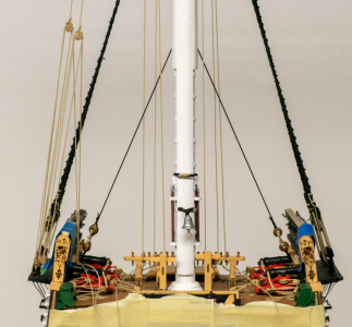
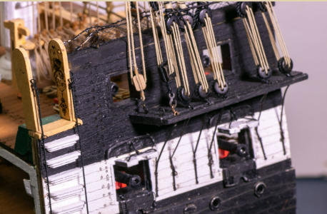
In seeking clarification on the block and rigging setup for the halliards, I started looking at build logs here for the Constitution's Cross Section - the MS kit, since that seems to include the halliards and jig tackle for the main mast. I found a build by Jeff T, photos follow:

If I read the MS kit plans correctly for the halliard details on the main mast, on the starboard side channel, which I believe is on the left here (the bell is mounted on forward side of the mast, yes?), we should see one of the two top sail halliards and its jig tackle, as well as the lone royal halliard and its jig tackle. I think that's what I'm seeing in this photo. The plans call for a pair of double blocks for the top sail jig tackle a double and single block combo for the royal jig tackle. I'm pretty sure that the top blocks are doubles, but I can't really tell what's going on with the bottom blocks.

1786813288215.png

are they both singles? Hard to tell...
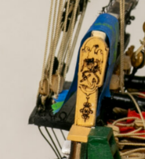
Note also how close to one another these blocks are.
1786813787771.png

Again, I believe I'm looking at the starboard side here. The outermost block seems to be a single. Possibly the jig tackle for the royal.
1786813028685.png


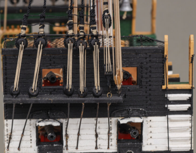
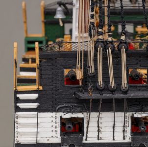
My plans for the port side say that the second top sail and the topgallant halliard are rigged here. They call for double blocks all the way around for the jig tackle - top and bottom. But I only see one single block here. I think the triple block to the right of it is part of the rigging for a stay.
1786812982033.png

and the second eyebolt is not being used?
1786813090445.png

I am no less confused now than I was before.

Reached out to Jeff T, hoping to get a copy of the plans for the rigging of the halliards. Here's hoping he's still monitoring his build log.
 
It's never too early to start learning a foreign language. Especially one as complicated as shipyard Greek..

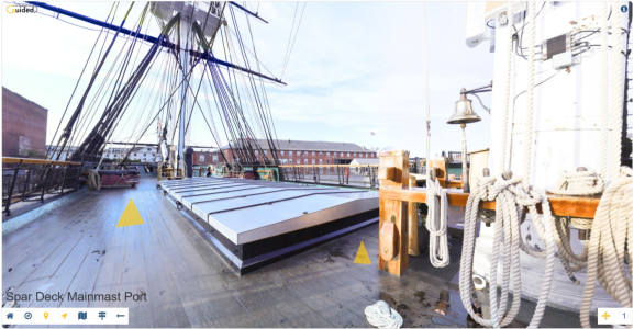
It's too bad that the virtual tour of the Constitution doesn't actually show the rigging in question. It does make me wonder what's holding up those yards.
 
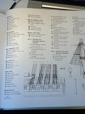
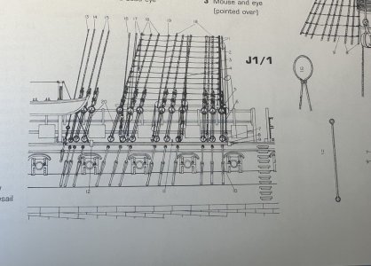
Not finding anything (yet) in Olaf's book, but here's a couple images from Marquardt's AotS standing rigging diagrams. Do these help? Is it the #13 & 16 lines you are asking about?

IMG_9555.jpegIMG_9556.jpeg
 
by the way, I went to the Dry-Dock models and parts site, and had to dig, but I did find the "upgrade pack". If you were going to buy all the blocks you need for Conny, that price for the complete set is substantially less than the cost of piecing together individual orders for the blocks yourself.

It would be nice if they offered an "upgrade pack" for rigging too. I was working on the main royal yard and thought I'd add the halyard while I had the yard in hand. The Hunt practicum said this was a 36" long piece of .015" rope (.40ish mm). I thought to myself, that can't be right, so I checked the plans to see where the other end of the halyard ended up. Holy cow! Did that exercise open a can of worms.

The good news? The halyard doesn't run all the way down to the channels, so 36" length seems overkill.

The bad news? The plans call for "eyebolts on channel inboard of backstays". Say what???

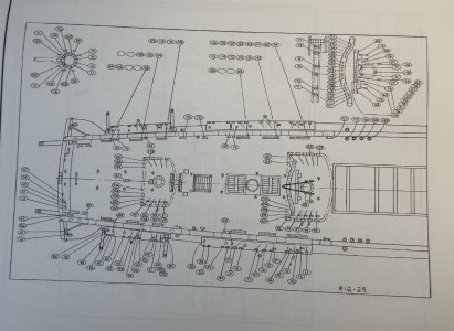
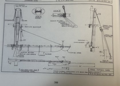
The plans don't reference this on the page that shows where the deadeyes and eyebolts for the stays are displayed. Neither does the the Hunt "practicum" mention this in the chapter where he details making the channels. You would think those would have been the time to mention this, no? Well, here's the reference to the halyards on the rigging plan from the kit:

View attachment 625848

and the Hunt practicum finally addresses this in the very last chapter on rigging the running rigging. He casually mentions the eyebolts here, long after it would have been easy to install these.

Jack and Gregg, I'm thinking of joining you both on that break from Conny. I'm calling it a day and going home to a double adult beverage.

well, i had a look at that book Anatomy of A Ship ,specifically page 105 and I see that the fore royal yard halyard is tied to the fighting top and belayed somewhere below, probably the fore pin rack is my guess. That makes a lot more sense to me.
 
Even the MS plans show where on the pin rails the ends tie up to. I'm fairly certain the feedback from JeffT settles the issue.

Double blocks on top of the jig tackle. Single blocker at the bottom. Sizes are available on the bottom right diagram of the running rigging page of the MS plans. Location of eyebolts hinted at, but probably at the aft end of the channels. The way I read the plans, only two eyebolts needed per side.

 
Even the MS plans show where on the pin rails the ends tie up to. I'm fairly certain the feedback from JeffT settles the issue.

Double blocks on top of the jig tackle. Single blocker at the bottom. Sizes are available on the bottom right diagram of the running rigging page of the MS plans. Location of eyebolts hinted at, but probably at the aft end of the channels. The way I read the plans, only two eyebolts needed per side.

Glad you figured it out. I haven't though. lol
 
I figured out the discrepancy, if you can call it that. The MS kit is based on the 1927 redesign of the ship which includes running halyards to the channels. I am working on rigging it based on the 1812 version. Why because I am a glutton for punishment.
Anyways, many successes with your model. Just wanted to clarify this point.

Cheers
 
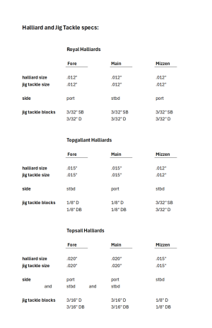
I'm going with the MS specs for the halliards and jig tackle.

I'm not sure why the plans aren't consistent labeling Double Blocks. Single blocks seem to be labeled SB, but unless there's a secret code I'm not aware of, Double blocks are labeled DB or D.

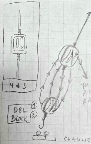
The channels for the fore and main masts would appear to have two jig tackles attached to eyebolts at the aft end of both port and starboard sides - totaling four eyebolts in all. Location seems to be anyone's guess. I plan to orient them perpendicular to the hull at almost the very end of the channels. The mizzen mast would seem to have only three eyebolts - two on the starboard side, and one on the port.

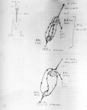
In all cases, the other end of the jig tackle ends up secured to belaying pins on the bulkhead pin rails.

1786926963258.png

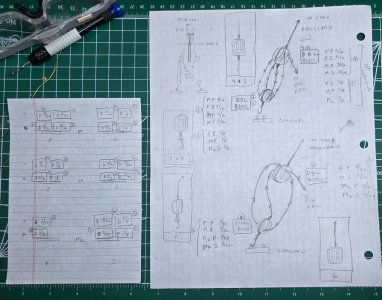
This is how I think the jig tackle are rigged. Double double block configuration on top right, Single/double block configuration on bottom right.

1786928478490.png

To keep me organized, I Amplified on the above.

20260817_112402.jpg


Thoughts?
 
Last edited:
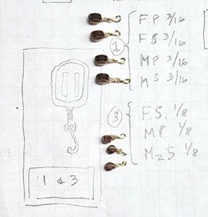
Hi. Quick question. I see there are some hooks that will be needed. Did you make them yourself? I don`t see any in my kit.
 
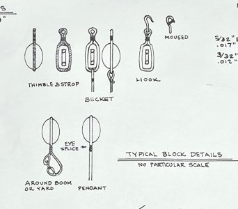
Thanks to a reply from Tom at the other website, I now know what the B stands for in the labeling for the blocks.

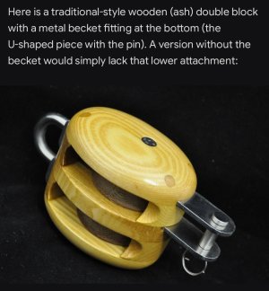
This is the designation for a Becket block. What is a Becket block? You may well ask..

Screenshot_20260818_102937_Grok.jpg

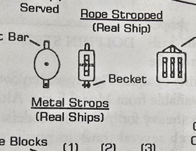
I even found a reference in the MS instruction book on page 36.

20260818_103620.jpg

And another one Page 7 of the rigging profile supplied with the MS kit. Note that in this instance, it seems more like a suggested method of rigging than adding metal attachment. Feed a line under the strop?

20260818_110608.jpg


Given the scale that I'm working in, with even smaller blocks than those supplied by the MS kit, I will be stropping and seizing line, wherever Becket blocks are called for,

Like here?

20260818_104445.jpg

instead of attempting to install a Becket.
 
Last edited:
Back
Top