
Paul I would love to see you build this ship. I hope it goes on your list of interest.It's hard not to want to build this ship, Daniel. The framing just makes me smile. Unfortunately, I would need to swap out all the wood...

 |
The beloved Ships in Scale Magazine is back and charting a new course for 2026! Discover new skills, new techniques, and new inspirations in every issue. NOTE THAT OUR NEXT ISSUE WILL BE July/August 2026 |
|
 |
As a way to introduce our brass coins to the community, we will raffle off a free coin during the month of August. Follow link ABOVE for instructions for entering. |
|
Paul I would love to see you build this ship. I hope it goes on your list of interest.It's hard not to want to build this ship, Daniel. The framing just makes me smile. Unfortunately, I would need to swap out all the wood...


Hello Russ, I have a couple of gun carriage rigging options in mind. Build out 4 canons complete with rigging attached then thread the tackle ends into their respective holes with glue via long tweezers. I would have to glue down the wheels as well. This would be much easier accomplished without any deck boards in place but not impossible even with decking boards in place. Since I will be inverting the ship to place all the outer hull boards plus sanding and probably some rougher than I would like handling, I don't really want to put the canons in now. Even though I would love to finish out the upper decking, I'll probably wait till the hull planking is finished first. Then place the 4 canons then finish the upper decking. I needed the upper deck support beams in place first to stiffen the whole upper frame so it's all a critical path problem for me.That is coming along beautifully Daniel. I agree with Paul, watching your progress, it is quickly making it's way onto my "wanna" list.
You mentioned earlier that you drilled the holes for your cannon rigging while you still had the room. Inquiring mind want to know, now that you have all those closely spaced beams in place, just how do you plan on actually rigging the guns? It's a pretty tight squeeze in there.

 - clearly you are doing this justice. What a cool looking build- so interesting. Cheers Grant
Thanks Grant, this ship has all the qualities we love; a big Challenge, a boatload of Char (debatableAhhh Daniel, you should get commission from ZHL as we all want to build this model now, myself included.
), and so much Cussing your swear jars will always be full! However, when finished, one of the coolest looking ships to ever set sail.
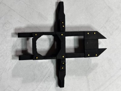

Thanks Paul.Brass pins look good on the black. Nicely done.

Thank you, Roger.Interesting stabilization/bracket fixture Daniel, I like it. You did a nice job of it.

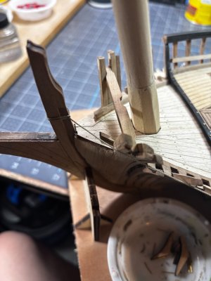
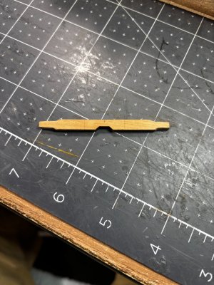
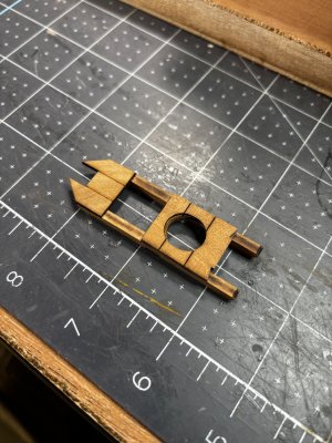
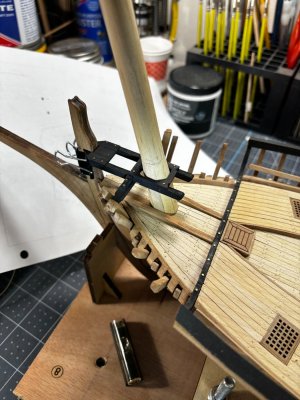
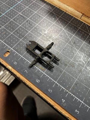
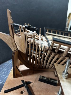
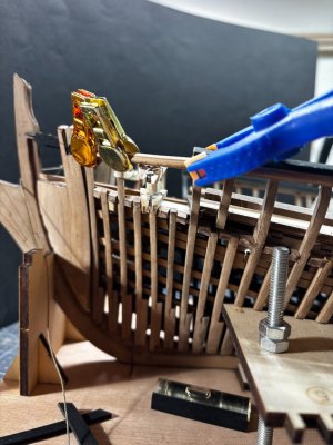
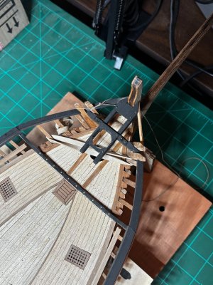
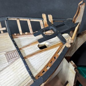
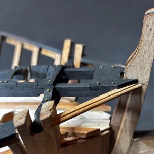
A nice assembly of various parts for this special construction, Daniel. Almost everything on this type if ships is ‘special’.Here is a fun little part I put together today. In Chinese it's called a foremast fixing bracket which is close enough to what I would call a foremast stabilization bracket. Here are some as built photos. First photos show trial fitment. Notice the diameter of the opening at about 5/8".
View attachment 631056View attachment 631057View attachment 631058
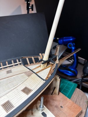
Here's the finished product dry fitted.View attachment 631059View attachment 631060
View attachment 631061
I wanted to point out how much I had to hollow out the opening in order to make this mast stabilizer system work. The hole has to be oversized in order to slide and accommodate the larger sections of the (hex shaped) mast through the support. When I built the mast some time ago, I matched the drawings and fabricated a snug fit opening in the deck. Somewhere there is a disconnect between the plans and the laser cut parts, or between the plans and my old brain. Ha! Anyway, now the fat part of the mast will pass through stabilizer, and I will need to fabricate some type of closure to tidy it up down the road. This tidbit had to be accomplished before I could finish the top railing so I would know where and how to dog it all off.
Thanks for looking in, till next time!
Thanks Peter, I'm thankful for the challenges this hobby has to offer. It certainly keeps my mind active.A nice assembly of various parts for this special construction, Daniel. Almost everything on this type if ships is ‘special’.
Regards, Peter
A very true story.However, when finished, one of the coolest looking ships to ever set sail.
Good morning Daniel. Everything on this ship just looks so cool. Nicely done- this is not as easy as you made it look with the angles, alignment and of course the thicker base of the mast-Kudos. Just for fun I think I will call it a foremast support structureHere is a fun little part I put together today. In Chinese it's called a foremast fixing bracket which is close enough to what I would call a foremast stabilization bracket. Here are some as built photos. First photos show trial fitment. Notice the diameter of the opening at about 5/8".
View attachment 631056View attachment 631057View attachment 631058
Here's the finished product dry fitted.View attachment 631059View attachment 631060
View attachment 631061
I wanted to point out how much I had to hollow out the opening in order to make this mast stabilizer system work. The hole has to be oversized in order to slide and accommodate the larger sections of the (hex shaped) mast through the support. When I built the mast some time ago, I matched the drawings and fabricated a snug fit opening in the deck. Somewhere there is a disconnect between the plans and the laser cut parts, or between the plans and my old brain. Ha! Anyway, now the fat part of the mast will pass through stabilizer, and I will need to fabricate some type of closure to tidy it up down the road. This tidbit had to be accomplished before I could finish the top railing so I would know where and how to dog it all off.
Thanks for looking in, till next time!
. Cheers Grant
Perhaps the best description yet Grant!Just for fun I think I will call it a foremast support structure


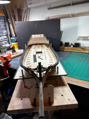
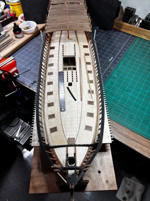
Thanks Paul, as long as I have the desire and can picture the outcome, then I'll be up to the task.Tricky construction, Daniel. It would seem you are up to the task.
Thank you John, I imagine the designers of this model and the CAD programmers of the laser cutters had their work cut out for them. Ha! accidental pun!Daniel,
This log is really something - your work is so "up there" And this ship from ZHL is also an excellent product, and well though out on their part.
Even with the few frustrations that you're encountering along the way
Regards