• Ships of Scale has incorportated an extra level of security when you log In. Please follow on-screen prompts to acknowledge that you are not a robot via a "Check Box" or a "Pictorial Check Box Puzzle". This is needed due to higher level of AI Activity Security.
  • SUBSCRIBE TO SHIPS IN SCALE TODAY!

    The beloved Ships in Scale Magazine is back and charting a new course for 2026!
    Discover new skills, new techniques, and new inspirations in every issue.

    NOTE THAT OUR NEXT ISSUE WILL BE July/August 2026
  • Win a Free Custom Engraved Brass Coin!!!
    As a way to introduce our brass coins to the community, we will raffle off a free coin during the month of August. Follow link ABOVE for instructions for entering.

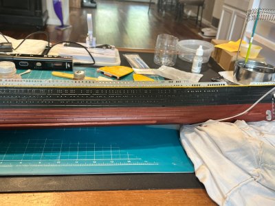
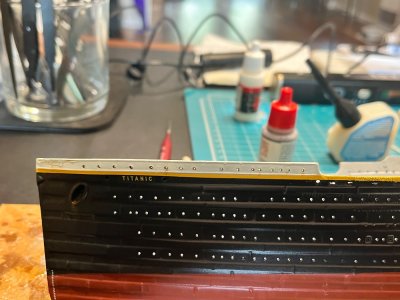
RMS Titanic minicraft 1:350 Scale

Hi Pete!

Great work on all of the hull details. I think your decision to limit your time investment on the stern plating was wise. It’s easy to get lost in the world of Titanic model hull enhancement when there is so…much…more…work to be done on the superstructure. ;) I learned the hard way that most of that detail tends to disappear when the black paint is applied.

I’m building the Trumpeter Titanic. While it’s a different kit, you may still find some useful info in my build log here: https://shipsofscale.com/sosforums/threads/titanic-trumpeter-1-200-by-inkmot.13004/

-Peter (InkMot)
Hi Peter,

Thanks so much for the nice words. I was inspired by your post on the Trumpeter kit from your build logs. I saw the great work you did on the stern plating stage of the hull work you were completing. That was the same picture you posted on the Olympics' stern, that I too, wanted to follow the same idea. Since there is no stern hull plating kit in 1:350 scale that I know of, I decided to scribe the transom plates by hand following Ben at The Model Shop instructions. I just converted the scale and measured about 1000 times before I started. I am little jealous of the nice aftermarket accessories available in 1:200 scale.

Great Log and thanks for the Inspiration

Pete
 
Pete,

Just found your log -- will go back an spend time going over all of your detailed information. Looking very good

Regards,
 
Pete,

Just found your log -- will go back an spend time going over all of your detailed information. Looking very good

Regards,
Thanks OldFlyer

I am happy others are finding my build interesting.
If I can inspire someone else like I have been inspired by everyone at SoS. Then I feel like this project is a success already
 
Rabbit Hole #2

SORRY... had a technical issue and had to post instead of save draft for some reason??? Probably because I was born before 2000. I know I left the log unfinished, but it is working now. Anyway back to the log

I count researching and purchasing aftermarket accessories my #1 Rabbit Hole

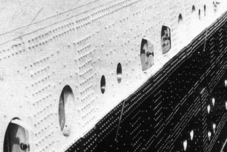
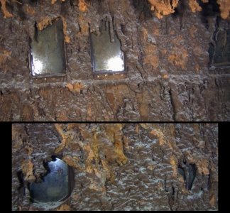
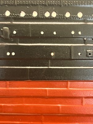
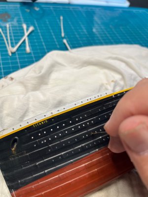
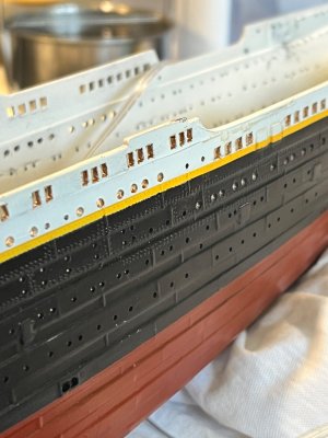
So doing my due diligence and researching how the portholes looked glazed on images of the Titanic (photos, Bob Read articles, virtual images), I found that all state that there was brass and bronze portholes and window frames because it is resistant to sea corrosion. However, the exterior frames where painted the existing hull color.

Porthole 4.jpgPorthole 3.jpg

So I took a leap and picked an isolated porthole in both the black and white areas of the hull. This way I can repaint the base color if I down like it. But you know, I did like it. It gives the hull a three dimensional look

IMG_3341.jpeg

The picture to the right is the same porthole on the left with a further closeup painted and glazed.

IMG_3340.jpegIMG_3356.jpeg

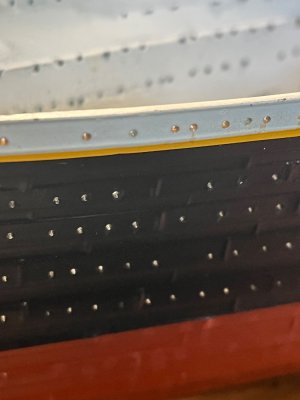
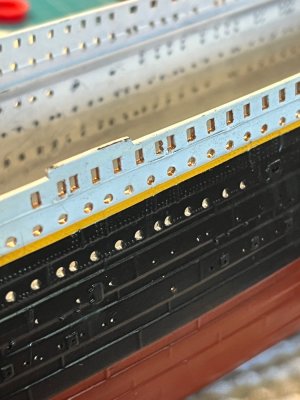
When you add Krystal Klear window maker, it comes out where you can only perceive the brass up close

The larger .7 mm portholes on D-Deck and C-Deck will have the sides of the exterior painted the appropriate color (These larger portholes were more rectangular with a rounded top and bottom. So then I guess I will have to take a very fine brush (00000000 :P) and paint the exterior sills and the hull colors after glazing.

Porthole 1.jpgPorthole 2.jpg

The windows have Utley's sliding glass window system and can clearly seen the brass framing.

Porthole 6.jpgPortholes5.jpeg

So after using a very fine awl I reamed the portholes and windows with Testor's brass enamel paint and cleaned off any excess outside of the interior to preserve the existing hull colors. The pictures shown are pre-touch and cleaning.

IMG_3363.jpeg

IMG_3342.jpeg IMG_3340.jpeg

I also found out where I have to fix windows that were not square after taken these photos (Closeup photos shows all the bad things).

And the view from 5 feet away (It all disappears).

IMG_3357.jpegIMG_3358.jpeg

Anyways, I like it and it gives some depth and interests to the windows and portholes.

Facts:
Titanic had 1116 portholes and 419 rectangular windows according to titanicfacts.net.

My model does not have that many to be sure, but there is a lot of them and I will be spending time completing my rabbit hole

Happy Modeling -Pete

IMG_3340.jpeg

IMG_3341.jpeg

IMG_3342.jpeg

IMG_3356.jpeg

IMG_3357.jpeg

IMG_3358.jpeg

IMG_3359.jpeg
 
Last edited:
Very nice. I love little details like this. It really sets the model apart and as you said, provides some additional depth and interest for anyone giving it a close up look.
Awesome work
 
B and C Deck Forward Structures

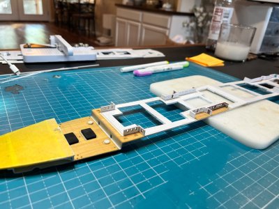
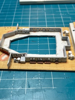
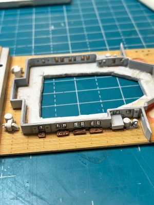
I started with the forward section of B-Deck because of my plan to build sections or modules and then install them when appropriate. For example, I would complete everything on the B-Deck level on part D1 (Forward B/C Deck kit piece) before I installed it in the hull.This way, I can complete that section and ensure a tight and level fit outside the hull for accessibility and clamping ease.

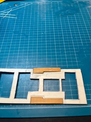
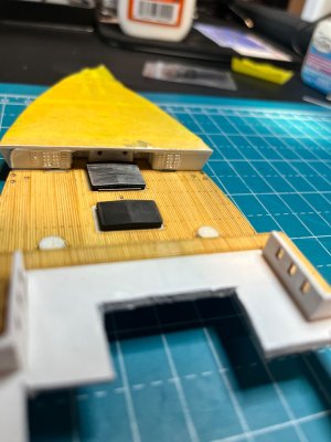
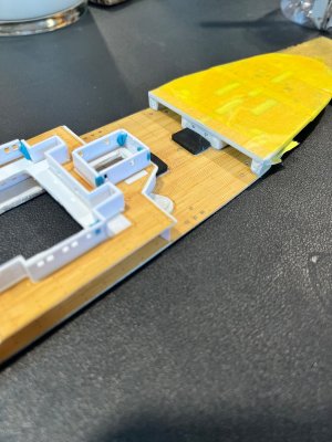
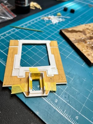
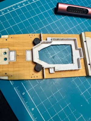
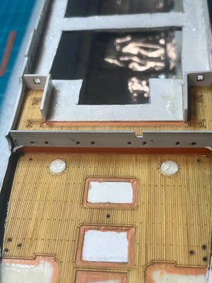
I started with installing the Artwox wooden deck veneer on the well decks, B-Deck 2nd Class forward promenade, The 1st Class B-Deck Entrance and Reception areas, and the Private Promenades (I did the same for the aft B/C Deck areas on part D2)

IMG_3132.jpegIMG_3153.jpeg

Then kit parts J13 A & B had to be modified

IMG_3130.jpeg

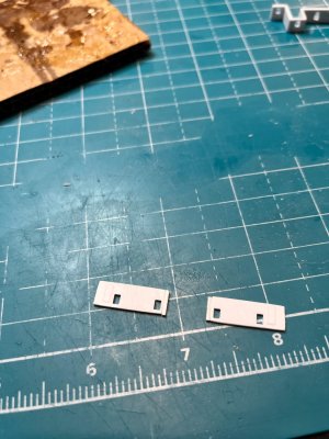
This part is missing a 3mm x 2mm window past the 90 degree corner which I created on both pieces.

IMG_3148.jpeg

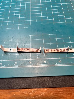
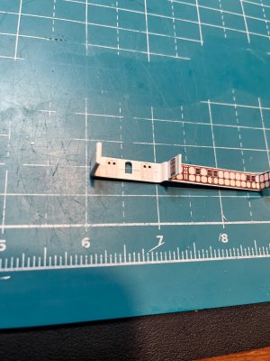
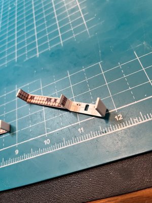
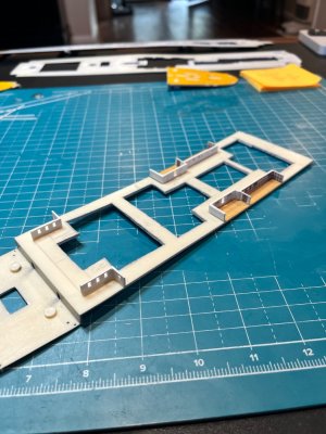
Next is the the kit parts J37 A & B which constitutes the 1st Class Entrance and the Private Promenades. But I want some details versus the plain white plastic wall that the kit provided.

IMG_3129.jpeg

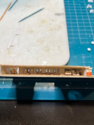
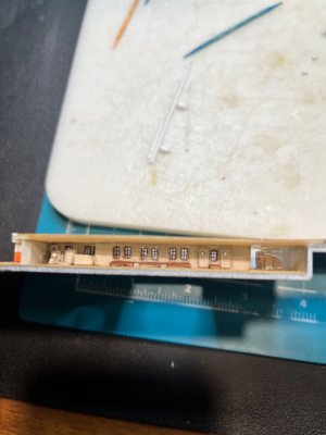
There was no bulkhead provided that separates these two areas that can be theoretically seen from the windows. Therefore, I created one out of 0.5 mm sheet plastic. I initially tried to create the private promenade intricate design features on a cut piece of styrene. No I did not take any photos because it started out clunky and ended in disaster. The space was 6 cm long by 7 mm height. And I could not make a decent representation without it looking cluttered and out of scale. Know I have seen those who make such intricate scratch built pieces in microscale, but I need more experience at that level to make that kind details that look correct :( I need another approach!

I went a head and completed the walls and primed, then painted flat white all my walls described herein while I pondered.

So I thought that if I could get a plan layout of that room and others. Print it off at scale using some of my wife’s photo editing programs (yeah right). My original plan was to make the wall pattern to scale on paper with spruce and small sized bars (0.25mm x 0.25 mm) before transferring the completed wall pattern to the plastic walls (So many different issues I could write a book). But I found a website titanic-ma.weebly.com with the floor and favorite room wall pattern images that can be downloaded for 1/350 scale specifically (Thank you!). I decided it was time for more magic :)

Remember that the viewer will have to be up close and looking through these specific glazed windows to see any of these details. Return of investment time again.

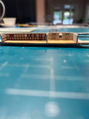
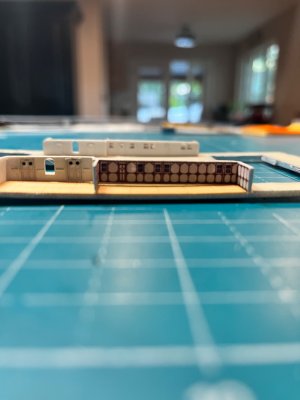
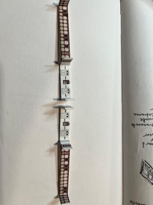
I will cut the walls out and glue them to the surface of that specific room. From squinting inside you can see the crisp details I desire without it being an obvious out of scale illusion. You can see the paper pieces cutout before installing.

IMG_3129.jpegIMG_3131.jpeg

Once attached I then added a little more green on the lower panels of the promenade walls to make them stand out. The printed windows actually fits over the kit windows and should present a subtle light effect like a curtain drawn over the window (fingers crossed). I also installed the double doors that opens to the 1st Class Reception Areas leading to the Grand Stair Case. And Viola!

IMG_3133.jpegIMG_3134.jpegIMG_3135.jpegIMG_3136.jpegIMG_3137.jpegIMG_3139.jpeg

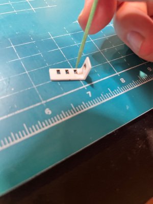
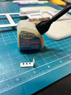
I then added window frames for the entrance and glassed the window with Testor’s Window Maker cement.

IMG_3150.jpegIMG_3151.jpeg

Now you can see the pieces dry fitting onto the deck with glass installed.

IMG_3148.jpegIMG_3147.jpeg

Just the individual sections for the forward section of B/C Deck layout.

IMG_3147.jpegIMG_3153.jpeg

Then the real fun begins with my next post on the aft B/C Deck structures.

Thanks for all the support and interest. I learn so much following your build logs and the techniques you share.

Happy Modeling

IMG_3129.jpeg

IMG_3130.jpeg

IMG_3131.jpeg

IMG_3132.jpeg

IMG_3133.jpeg

IMG_3134.jpeg

IMG_3135.jpeg

IMG_3136.jpeg

IMG_3137.jpeg

IMG_3138.jpeg

IMG_3139.jpeg

IMG_3147.jpeg

IMG_3148.jpeg

IMG_3149.jpeg

IMG_3150.jpeg

IMG_3151.jpeg

IMG_3153.jpeg
 
Last edited:
Aft B/C Deck Structures

Now the aft structures are far more complete and complex than the forward B-Deck structures. The forward deck piece D1 has a nice even break at the aft bulkhead locale of the fore well deck. The actual forward structures are on B-deck proper. There are two actual sections I must complete on the kit deck piece D2 before I can install them in the hull. And I must first complete the 2nd Class Library and its forward aft well bulkhead to complete the perimeter of the well deck. Then I need to install another B-Deck extension kit piece I2 as the library’s roof and the flooring of the rest of the aft B-Deck structures.

IMG_3152.jpegIMG_3117.jpegIMG_3116.jpegIMG_3163.jpeg

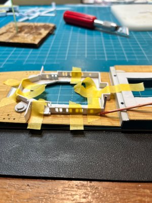
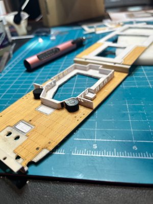
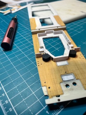
As I posted earlier, I installed the wooden deck veneers on the aft sections of the deck pieces and had no issues. Then I dry fitted the 2nd Class Library bulkheads with tape and found out early that I would need to complete the walls off-deck.

IMG_3159.jpegIMG_3152.jpeg

This became obvious by the poor connection points on each of the walls that needed putty, sanding, and painting before attaching the piece to the deck. This includes painting the forward C-deck well bulkhead its dadoe line before I can continue to the B-deck proper structures. I also dry fitted other structures on kit piece I2

IMG_3163.jpegIMG_3162.jpeg

I then started working on all the aft structures so that I could paint them all at a the same time. The square 2nd Class B-deck aft entrance and at the end was completed with no issues, but the 1st Class Al A Carte restaurant and Cafe Parisien walls was another matter altogether.

IMG_3167.jpegIMG_3168.jpegIMG_3171.jpegIMG_3172.jpeg

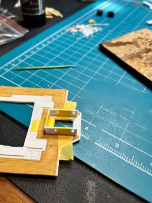
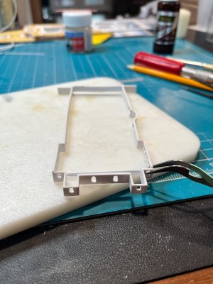
You may notice on the last two pictures show kit parts J25, H6, & H7 does not have a back piece that makes a four point connection like the other structures. H6 and H7 are long pieces and will not stay secure after cementing them together and then manipulate them for putty and sanding. Therefore, I attached some scrap styrene cut to size to act as a brace and the fourth wall. I will remove this piece once it is installed on the deck. The other benefit making these structures off-deck is that I can add additional details that can be seen through the rectangular windows on the Cafe Parisien and Ala Carte interiors.

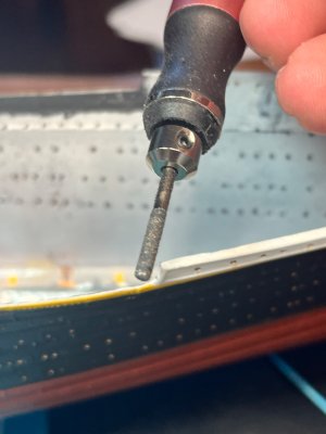
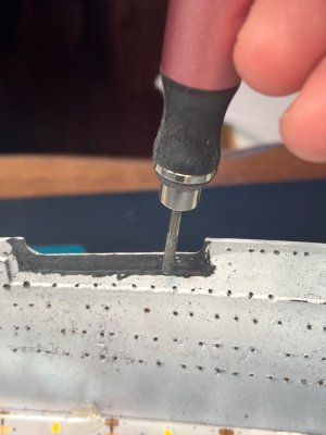
It was then when I was starting the dadoe line painting that I noticed then my aft well deck 3t crane bases did not need to use the protrusions where the kit crane bases would be installed. So I had to grind off those molded pieces on the deck after I had already installed the wooden decks (Opps :( ) I ended up taping in the deck with Tamiya tape and use a conical grinder bit without issue. I then used tongue depressors to clamp down the 2nd Class Library.

IMG_3224.jpegIMG_3167.jpegIMG_3164.jpegIMG_3165.jpeg

You can see the crane bases next at its installation points to the C-Deck bulkhead at its correct positioning and levels.

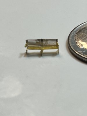
Now I can install some of the deck details at the exterior of the library. I made benches (8) using Vasilije Ristovic and the Hope and Glory images as reference to modify kit benches H6 (these things are pretty bad and have few uses except making furniture) painted like benches. There are also some deck equipment thermotanks that are near the “box” like structure and forward bulkhead sides. I ended up removing and modifying that box like structure (that looks like a storage box for the restaurant?) in order to install the equipment piece.

IMG_3221.jpegIMG_3220.jpeg

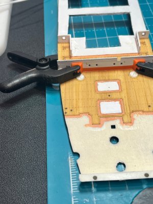
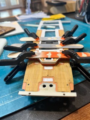
Next was installing the kit piece I2 and secure it level and no light leaks using my tongue depressors again. You can see the 2nd Class Library after deck installations.

IMG_3224.jpegIMG_3229.jpegIMG_3230.jpeg

Then the restaurants section. I decided to use the wall pattern available in 1:350 scale at titanic-ma.weebly.com for the Cafe Parisien. I installed Tom MW bay windows specifically for the Cafe and primed and painted the walls. I then glued the intricate pattern walls and added styrene doors where appropriate. I added “dots” of PVA glue at the terraces to simulate the English Ivy that grew there and used different shades of green dots for depth.

IMG_3197.jpegIMG_3198.jpeg

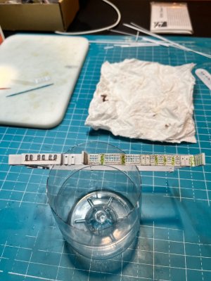
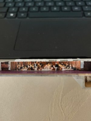
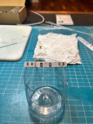
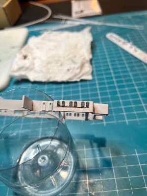
For the Ala Carte Resutaurant I used AI and requested a scene of the Ala Carte Restaurant on the Titanic at 1:350 scale. I had to give the dimensions of 7 cm long by 7 mm height and the direction of the view from the portside B-Deck windows. I then cut a piece out to kit part H6 5 cm long by 4 mm height leaving a 3 mm bottom edge for good adhesion surfaces. I glued my image to acetate as a backer and then glued that to my kit piece. I am hoping for more magic by illuminating the image from behind and making it visible with the backlight. You can also see where I glued the rose colored floor pattern for the Ala Carte room.

IMG_3332.jpeg

I also added the windows at the aft exterior restaurant bulkhead (that is partially obscured by the 2nd Class aft entrance and the B-Deck extension part I2). There were also details that are visible to the 2nd Class aft promenade like the double doors and hand rails.

IMG_3199.jpegIMG_3200.jpeg

I then installed the restaurant structures to the deck that goes over the extension piece I2. Again every precaution was used for light leakage and level installation using clamps.

IMG_3251.jpeg

Finally I am ready to install the B/C Decks sections into the hull when I finish the portholes and window brass project and glazing them for glass.

I started working on the furniture and tables that will be installed at the Ala Carte and Cafe Parisien restaurants before I start on the A-Deck. This includes pieces for the private promenades like the Photo Etch lounge chairs and benches from GMM. This is a tedious task made easier by a jig to form the benches curves that I will provide in another post

I will finish these structures and provide pictures prior to installing A-Deck.

Happy Modeling - Pete

IMG_3152.jpeg

IMG_3160.jpeg

IMG_3164.jpeg

IMG_3165.jpeg

IMG_3166.jpeg

IMG_3332.jpeg
 
Last edited:
Sorry I posted too early again. I am all thumbs with uploading pictures from my phone :P

I had a short break but back to modeling

I have been glazing portholes and the tedious task of making benches and furniture for the decks and restaurants.

I searched and searched for anyone making any furniture at 1:350 scale. The closest I got was model railroad Z scale (1:440 scale) that was close to period appropriate (includes 20th and 21st century's range) but still out of scale. all I found that had good reviews was a guy on Etsy making Star Trek model furniture for the 1:350 scale Enterprize (which I cannot modifiy into the 20th century).

So I started following the Rivet Counter (RC) guide to making furniture out of the existing parts from the kit. This required taking the grossly out of scale kit provided benches part H-5 and cutting them into thirds to make chairs. It also has a good guide to make tables. But I ran into a problem with the chairs, they dont look right :(

IMG_3247.jpeg

I placed them in order per plans that Bruce Beveridge created so that I had the approximate right number of chairs and tables. I am focused on the Ala Carte portion visible next to the portside hull windows and the visible part of the Cafe Parisien on the starboard. The Promenades have a different pattern that can be seen in all period photos.

IMG_3234.jpegIMG_3232.jpeg

I plowed on thinking that the chairs I was making would be very hard to see (I cringe just writing this). I painted the chairs and tables appropriate to the restaurant or room they were sitting in. I am working on the Cafe Parisien, Private Promenades, and the Ala Carte Restaurant on the B/C decks atm. When I finished and place these next to GMM benches and lounge chairs, I was disappointed. They were still out of scale! I was not satisified with the results.

IMG_3247.jpegIMG_3249.jpeg

Here are the dimensions that I need to be aware of inorder to scratch build these items according to Dr Google.

At 1:350 scale, 1 real foot is equal to only 1.04 millimeters (about 0.04 inches). A standard real dining table that is 3 feet tall and 5 feet long shrinks down to roughly 2.6 mm high and 4.4 mm long. Individual chairs are microscopically small (around 1.5 to 2 mm tall).

Actually the chair should have a height of 2.3 mm, width is 1.3 mm, and the seat cushion from the floor is 1.3 mm tall.

When I placed my efforts next to Tom's MW and GMM photo-etched deck chairs and benches they looked clunky and not the right scale. So back to the bench.

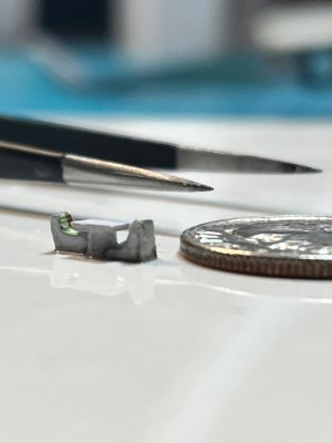
With that dimension information in mind, I went back to attacking those chairs. The chairs current state was 2.8 mm height and ~ 3 mm in width using the RC guide. I started the task of trimming down my chairs to approximately the right dimensions. I was able to halved the chair width and sand down the bottoms and here is what they look like now.

IMG_3438.jpeg

Much better and fits with the photo-etched details.

The tables where much easier to make. Dimension height 2.6 mm, table length 4.5 mm, and table width 2.4 mm.

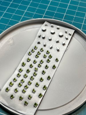
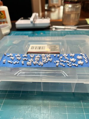
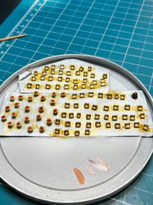
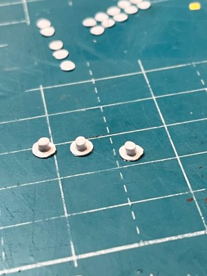
I started with 0.25 mm thick styrene sheet and cut out strips and sized for the appropriate number of rectangular table tops with a miter cutter. I then used a 1.5 mm diameter rod and cut them at 2 mm lengths for the table "legs", which ended up being a post as per RC's guide. I also used a hole punch device my wife uses in her crafting excursions that had the appropriate diameter for the small tabletops for Cafe Parisien/ Private Promenades, and the large circular tables for the Ala Carte restaurant.

IMG_3225.jpegIMG_3226.jpeg

I am currently attaching the re-modified chairs to the appropriate tables for easier installation as a unit after the B/C deck parts are cemented to the hull.

BENCHES

When I started with Tom's and GMM benches I immediately realized that the construction methods were completely different. I experimented with trying to fold GMM benches by hand. They came out ok with much fiddling, but the time requirements to get them to match was crazy.

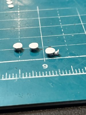
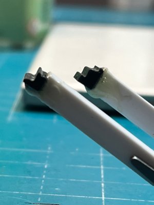
The particular curves at the bottom seat and the top backing is challenging. Then I remembered pieces that I received from China 3D was a approximation to the kit provided benches H5, which was weird because everything else was so articulated. I took a closer look because the shapes looked like the curves for the benches. Closer examination revealed that I can mount these on styrene tubes and use them as jigs (Hooray).

IMG_3440.jpeg

My first experiment worked perfectly by fitting the GMM flat bench part to the jig "bottom" and then lightly fitting/ squeezing the the other part of the jig on top to form the appropriate curves at one go :)

IMG_3442.jpeg

My one criticism with China 3D is no list of parts included in the purchase. I am glad I didnt just throw away these pieces as junk! anyways...

I completed 18 benches for the aft poop deck and was happy with the individual results, but when I started marrying the benches back to back I saw that I needed to fiddle some more to make the benches look symmetric . And since they will be prominent on the poop deck, I wanted them to appear identical to each other.

IMG_3325.jpegIMG_3326.jpeg

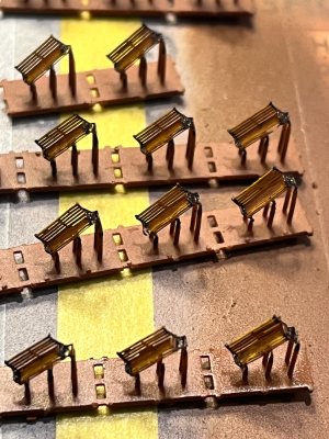
I completed the appropriate number and painted them in the traditional colors of iron for the metal work and a combo of wood paint base and tan highlights to make the teak look.

IMG_3257.jpeg

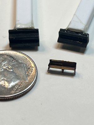
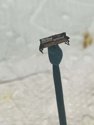
Then I saw that Ben at The Midwest Model Shop has 1:350 benches available at a good cost. They are fantasic and paint up really well (They are delicate so be mindful of removal, I used a sonic knife). They look great and solve my symmetry issues.

IMG_3329.jpeg

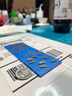
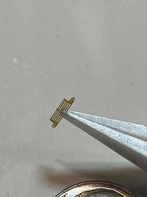
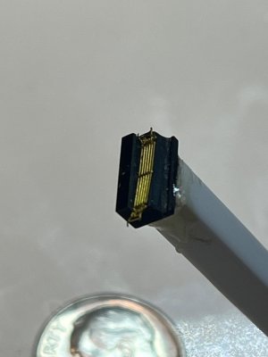
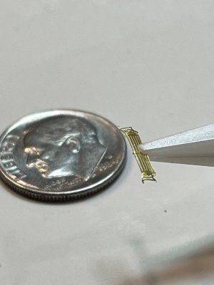
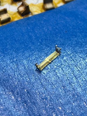
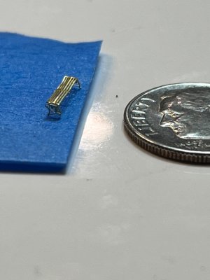
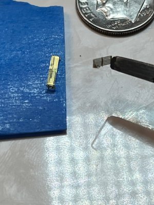
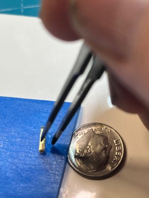
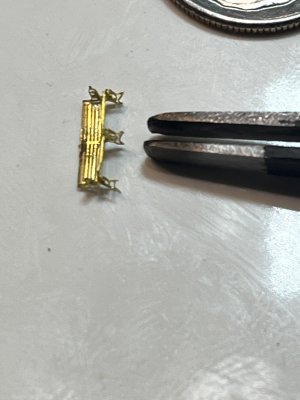
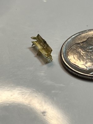
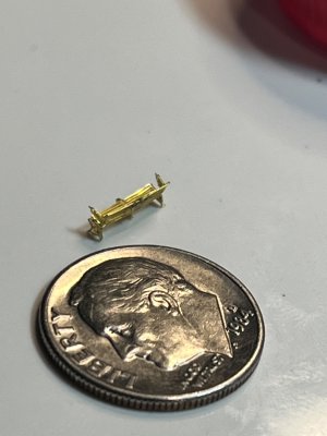
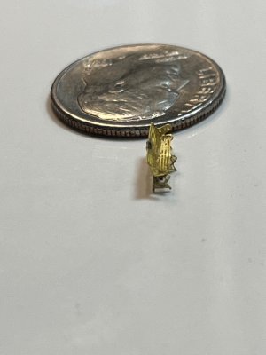
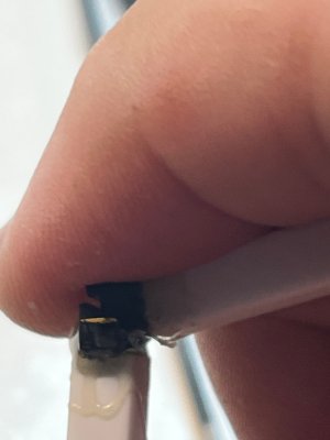
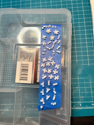
I will leave them on the sprue until I need them to protect the legs of the benches. No more fiddling with mirco parts to add the middle leg to the bench. BTW GMM benches actually come in three parts and need to have them fitted together. I found placing the folded bottom seat portion on blue tape to stablize it and then carefully guiding the backing part with the arm rest to its correct position (less fiddlying around). Key is to have fresh CA quick glue for that instant adhesion. You will then place the bench on its back with the seat facing vertically and guide in the middle leg at its position which is marked on the underside (can be fiddly but practice makes perfect)

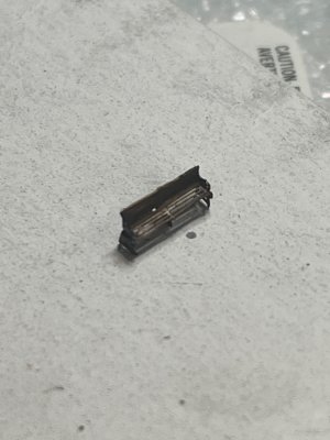
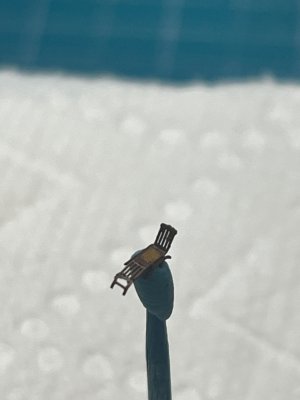
The lounge chairs from GMM are easy but very delicate because of the small legs.

IMG_3323.jpeg

Now plans call for 48 benches and half-benches for the titanic. but after reviewing different build guides I saw that 60 was a more appropriate number if filling some portions of the interiors (i.e. the private promenade had four each)

So I will use the 18 GMM benches that I made along with the 3D printed benches (50 total) to achieve that number if I need them (they pare well together).

I have to say that Art Braunschweiger's model of the Titanic at Cherbourg is amazing with the legs for tables and chairs scratch built for his interiors. I hope to reach that level of expertist someday. I will probably use his techniques at the upper A and Boat Decks interiors because the windows at much bigger and I need to be more precise.

More to come

Happy Modeling - Pete

IMG_3442.jpeg

IMG_3440.jpeg

IMG_3438.jpeg

IMG_3325.jpeg

IMG_3329.jpeg

IMG_3323.jpeg

IMG_3249.jpeg

IMG_3234.jpeg

IMG_3225.jpeg

IMG_3226.jpeg

IMG_3232.jpeg

IMG_3247.jpeg


IMG_3257.jpeg

IMG_3326.jpeg
 
Last edited:
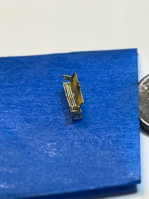
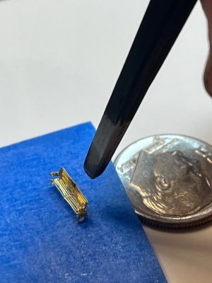
My buddy PM me and asked that could I show my techniques for putting the GMM benches together so that others may get ideas or tips. I was ok with this because I am a firm believer that the more tools you have in your toolbox, the more you can take on and tackle issues that might crop up. I have view many video high detailed builds and have collected some tips myself :)

To be fair I have a lot of experience in 3D metal puzzles and photo-etch parts like from Metal Earth, so I am not as hesitant to grip or bend these micro pieces. I was born before the 70's so my hand and eye coordination has deteriorated a little :p. So I had to modify my hand techniques with taping, bracing, and using reverse tweezers as a third hand to help hold things steady.

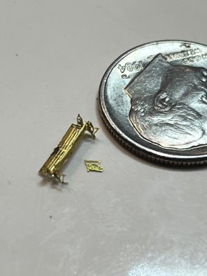
You will find that GGM benches come in 3 parts. The seat and the back seemed to be attached in one place but they are actually Facing each other in opposite directions. Therefore you must detach each piece.

IMG_3450.jpegIMG_3451.jpeg

The middle leg is very tiny and I kept it on the spruce until I need it.

Now I start with the top backing and place it in the jig as mentioned previous post. There is a front face so you want to place the piece with the arms facing towards bottom of the jig. Then you fit the other piece of the jig over the top of the brass vertically in line to the other post. Rock it gently back and forth and you will get a curve on the edge top portion of the bench backing. You finish the top by folding the arms away from the curve at a 90 degree bend.

IMG_3452.jpegIMG_3453.jpegIMG_3454.jpeg

The seat portion is handled the same way with ensuring that the “front” is now facing towards bottom you. The front can be seen by the direction of the legs as they lean to the rear. You will place the other piece of the jig at a perpendicular (90 degrees) to the bottom jig and rock back and forth gently. You can see the curve at the front portion of the seat. To finish fold the legs down 90 degrees (note: you can see a seam line in the middle of the seat. That will be the line we use to place the middle leg on the underneath side of the bench seat).

IMG_3455.jpegIMG_3457.jpegIMG_3458.jpeg

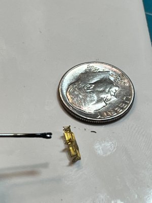
Now I fold the ends of a piece of blue tape to have a sticky side facing up. I set the seat portion on the blue tape and press gently to adhere it for stability. I then take my folding top backing with the arms facing forward. I lightly dip the bottom edge in thin CA cement and place that part on the backend of the seat. Ensuring it is properly centered at the back.

IMG_3459.jpegIMG_3461.jpegIMG_3462.jpegIMG_3463.jpegIMG_3466.jpeg

I then take my glue pen (a need with the eye cut in half in a pen vice) and add more CA along the edge between the top backing and the seat with a small amount of glue.

I cut out the middle piece and ensure it is at a proportional height (it can tend to be higher than the exterior legs and is more difficult to size when attached). I place the bench on its backside with the seat vertical. Ensure you have the leg piece in its proper orientation, dip it in CA and place it on the underside middle seam perpendicular to the seat. Finish this by adding lightly more glue on the middle leg to secure it.

IMG_3464.jpegIMG_3467.jpegIMG_3472.jpegIMG_3470.jpegIMG_3473.jpeg

Now is the time to reshape the piece once it has cured for a couple of hours by SMALL adjustments (more like nudges) so the the legs and arms are facing correctly. If you get CA adhesive in place other than the seams then use a line bit of Un-Cure CA remover and lightly brush then offending area and avoiding the seams. I used a fiber brush pen to remove any leftovers and check to make sure my seams are secured together properly.

IMG_3474.jpegIMG_3475.jpegIMG_3476.jpeg

And there you have it :)

Happy Modeling - Pete

IMG_3456.jpeg
 
My buddy PM me and asked that could I show my techniques for putting the GMM benches together so that others may get ideas or tips. I was ok with this because I am a firm believer that the more tools you have in your toolbox, the more you can take on and tackle issues that might crop up. I have view many video high detailed builds and have collected some tips myself :)

To be fair I have a lot of experience in 3D metal puzzles and photo-etch parts like from Metal Earth, so I am not as hesitant to grip or bend these micro pieces. I was born before the 70's so my hand and eye coordination has deteriorated a little :p. So I had to modify my hand techniques with taping, bracing, and using reverse tweezers as a third hand to help hold things steady.

You will find that GGM benches come in 3 parts. The seat and the back seemed to be attached in one place but they are actually Facing each other in opposite directions. Therefore you must detach each piece.

View attachment 622872View attachment 622873

The middle leg is very tiny and I kept it on the spruce until I need it.

Now I start with the top backing and place it in the jig as mentioned previous post. There is a front face so you want to place the piece with the arms facing towards bottom of the jig. Then you fit the other piece of the jig over the top of the brass vertically in line to the other post. Rock it gently back and forth and you will get a curve on the edge top portion of the bench backing. You finish the top by folding the arms away from the curve at a 90 degree bend.

View attachment 622874View attachment 622875View attachment 622876

The seat portion is handled the same way with ensuring that the “front” is now facing towards bottom you. The front can be seen by the direction of the legs as they lean to the rear. You will place the other piece of the jig at a perpendicular (90 degrees) to the bottom jig and rock back and forth gently. You can see the curve at the front portion of the seat. To finish fold the legs down 90 degrees (note: you can see a seam line in the middle of the seat. That will be the line we use to place the middle leg on the underneath side of the bench seat).

View attachment 622877View attachment 622879View attachment 622880

Now I fold the ends of a piece of blue tape to have a sticky side facing up. I set the seat portion on the blue tape and press gently to adhere it for stability. I then take my folding top backing with the arms facing forward. I lightly dip the bottom edge in thin CA cement and place that part on the backend of the seat. Ensuring it is properly centered at the back.

View attachment 622871View attachment 622870View attachment 622869View attachment 622868View attachment 622867

I then take my glue pen (a need with the eye cut in half in a pen vice) and add more CA along the edge between the top backing and the seat with a small amount of glue.

I cut out the middle piece and ensure it is at a proportional height (it can tend to be higher than the exterior legs and is more difficult to size when attached). I place the bench on its backside with the seat vertical. Ensure you have the leg piece in its proper orientation, dip it in CA and place it on the underside middle seam perpendicular to the seat. Finish this by adding lightly more glue on the middle leg to secure it.

View attachment 622866View attachment 622865View attachment 622864View attachment 622863View attachment 622862

Now is the time to reshape the piece once it has cured for a couple of hours by SMALL adjustments (more like nudges) so the the legs and arms are facing correctly. If you get CA adhesive in place other than the seams then use a line bit of Un-Cure CA remover and lightly brush then offending area and avoiding the seams. I used a fiber brush pen to remove any leftovers and check to make sure my seams are secured together properly.

View attachment 622861View attachment 622860View attachment 622859

And there you have it :)

Happy Modeling - Pete

View attachment 622878
All those beautiful little parts.... my compliments!!!
 
Prepping the B/C Decks for Installation

Hello Everybody!

Sorry for the delay in posting but I had a really busy August here in Colorado! 408 days till retirement :)

Well, when we last visited Pete's Titanic we were working on benches, chairs, and tables.

I also needed to get the hull and the B/C decks ready for installation. This is a big step and I need to get the all decks the correct depths, alignment, angles, and edges. The rest of the decks will follow after this installation and if its off, then all the rest will be off too. So what does that mean?

1. Ensure fitment of the decks are correct at the right depth, angles, and alignment (Numerous dry fitting, sanding, and grinding).
2. Modify decks and hull interior for aftermarket products (Bulwarks and C-Deck forward well bulkhead from China 3D forward).
3. Ensure all light leaks are addressed and to maximize the interior reflective surfaces inside the hull for illumination.
4. Prep the promenade windows on the hull for Testor's Window Cement after deck installation
5. Install all B-Deck walls onto the deck prior to hull installation (forward section including the forward B-Deck Promenade walls, and the 1st class B-Deck entrance, and the Private Promenade areas).
6. Install the B/C decks with minimal trouble and touch-up work.

Fitment and Modifications.
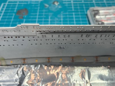
I first believed that I only had a little warpage on the hull with it pinching inwards at the mid-point of the ship about 10 mm on each side. This would actually be a benefit because it would lock in the deck installation without much filler or gaps. HAHAHA joke was on me. The hull sides did pinch-in, but the side shears of the upper portion of the hull were wavy too. Then there is the D-Deck large portholes on the hull that the overly thick B/C Deck can peak through and be seen if not aligned correctly.
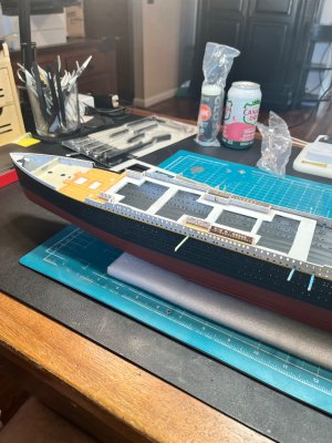
IMG_3597.jpegIMG_3574.jpeg

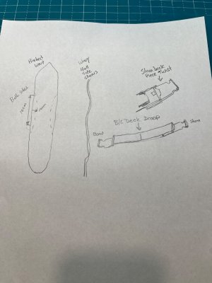
Not only those issues, but the decks warpage (though minimal) has both inclines and declines, and a little twist at the stern. I also have to ensure that the C-Deck forward well bulkhead is level with the Shears on the hull, that the angle braces are at the correct depth. Lastly was the fitment of the well deck bulwarks and trimming of the well walls to accommodate the added depth of the sides when installed. I drew an illustration to give a better visual that trying to capture all those issues for your understanding.

Once trimming, grinding, cutting, sanding, and cursing were to a point that I was ok with, I was ready for the next part (Many hours of dry-fitting and sanding).
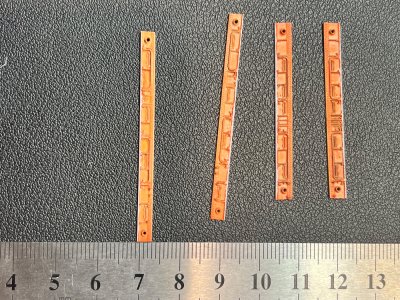
IMG_3572.jpegIMG_3579.jpegIMG_3585.jpegIMG_3584.jpegIMG_3584.jpeg

Hull Window and Porthole Prep.
I used red clear scotch tape to cover the interior portion of the promenade windows on each side of the hull. I learned this trick from watching YouTube videos on trains and how to cover the large window area with Testor's Window Cement. If a window or porthole is less than 2 mm in diameter, all you need to is take a dab of the cement and "pull" the adhesive to cover the opening, It dries clear and is durable. But on openings larger than 2 mm diameter, it becomes harder to cover the interior area with the pull method. I forget where, but I watched this video where a model train window at O-scale (~4 mm square) was first taped with the red label clear scotch tape on its interior, then the window cement was applied with the tape acting as support and covered a much larger area. This is what I will be attempting.
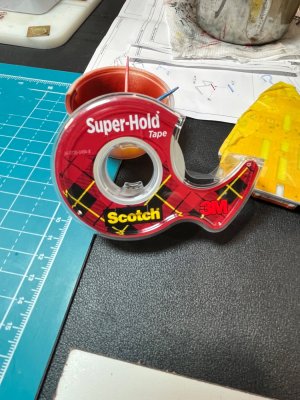
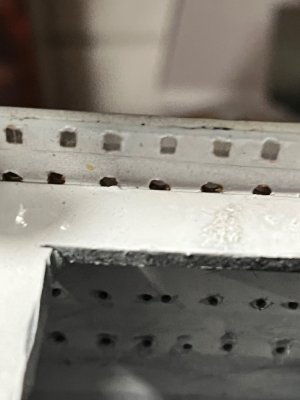
IMG_3591.jpegIMG_3595.jpeg

I did look at trying to use my wife's Cameo machine to cut acetate pieces to fit into my large windows. This ended in a failure I hate to say because I cannot find the right thickness of acetate to reliably cut the windows to the correct size to fit into the frame of the openings (BTW there is over 50 windows to install this way). The other issue was when I attempted to install these cut acetate windows on an extra kit piece with similar windows, it was difficult, tedious, and did not look right (all the angles of the panes MUST be the same or its obvious that its incorrect by looking like a face of a mirror disc ball. After much frustration, I nixed this plan and moved on to the window cement. this way the windows will theoretically self-level using the tape as a base, and will be "in" the window frames (I explored using the acetate just on the interior hull walls but the "glass" looked unrealistic only in the inside edges of the windows).

B-Deck Forward Promenade Walls and the 1st Class Entrance and Private Promenade Walls.
These were the last walls I need to install on the B/C Deck before hull installation. I saved these for last because the stern portion of the deck has multiple levels and structures that needed extra attention and care (See previous posts). The installation of these walls were handled the same with ensuring fitment, alignment, and light leakage were addressed. I did need to modify two interior bulkheads so that they aligned with the window frames (I don't need mysterious walls clearly bisecting the promenade windows).
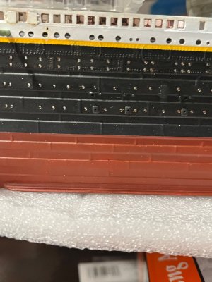
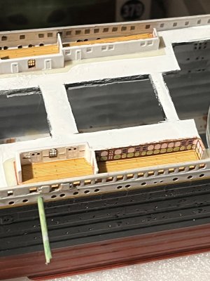
IMG_3594.jpegIMG_3596.jpeg

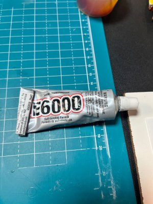
This included installing the forward C-Deck forward well deck bulkhead. This is a piece from China-3D and there is some fitment angles and alignment that need attention. This includes the curved angle pieces at the ends of the bulkhead that mount onto the top interior edge of the bulwarks (fragile!). I glued this piece with E6000 glue for durability so when I install the deck with the bulkhead, there is some flexibility and the piece will not "pop-off" when I am making my final adjustments just prior to adding adhesive (both E6000 and Tamiya Ultra Thin Cement).
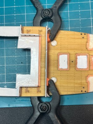
IMG_3589.jpegIMG_3582.jpegIMG_3580.jpeg

B/C Deck Installation.
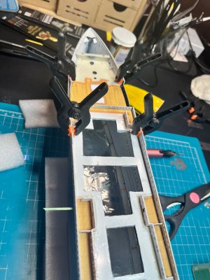
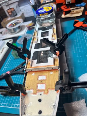
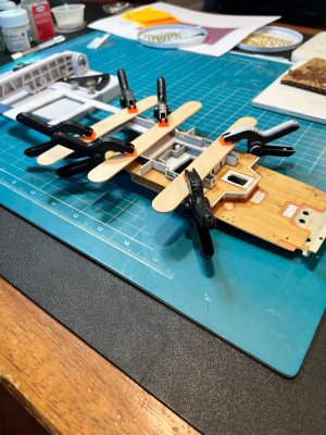
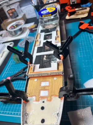
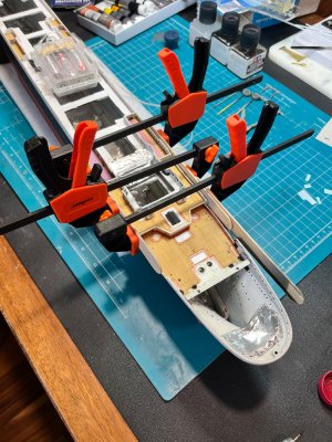
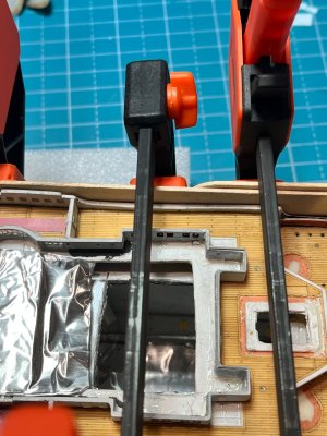
Now that I finally have the B/C Deck and hull prepped, sanded, and ready, I slowly installed them one at a time. I will have to address the upper portion of the hull shear's waves with 8" adjustable c-clamps, 4" and 6" spring clamps, and weights to push the deck in place. I first installed the stern portion of the deck to correct the twist by applying cement in incremental sections and allowing it to cure for 12 - 24 hours (depending the amount of adjustment I needed to secure the deck in its correct alignment).
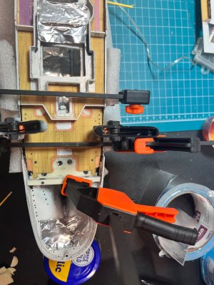
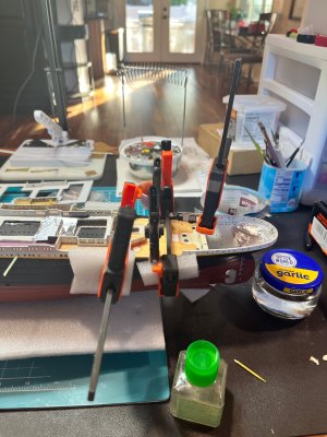
IMG_3578.jpegIMG_3576.jpeg

I place toothpick ends into the larger portholes on D-Deck to keep the edge of the B/C kit pieces from drooping into view. I also only glued about 15 cm section of the deck in place and allowed it to cure before moving on. This allowed me to address any unexpected fitment issues at the source and gave me a solid base to "adjust" the deck to ensure an overall smooth flow and alignment of the deck from bow to stern.
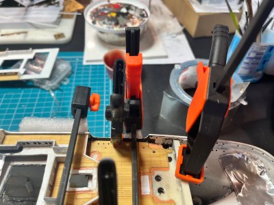
IMG_3578.jpegIMG_3576.jpegIMG_3577.jpeg

From the stern kit deck I moved on to the bow deck piece in the same installation method as above.
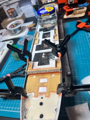
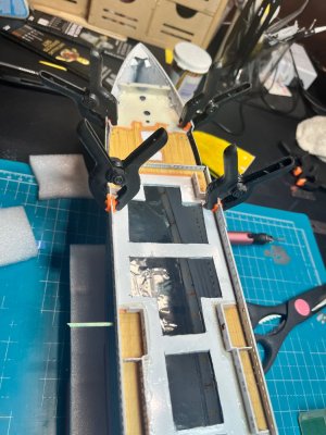
IMG_3587.jpegIMG_3586.jpegIMG_3586.jpegIMG_3587.jpegIMG_3590.jpegIMG_3588.jpeg

Once finished with the B/C Deck installation, I can then move on to populating the exposed areas like Cafe Parisian, Ala Carte Restaurant, and the Private Promenades with the details I previously worked on.


More to come and Happy Modeling - Pete
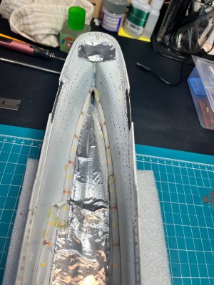
IMG_3580.jpeg

IMG_3572.jpeg

IMG_3568.jpeg

IMG_3586.jpeg

IMG_3587.jpeg
 
Last edited:
Pete, is Corvettes West the local corvette club in Greeley? Magic Mike

Sure is Been there for 41 years. I have been there for 5 years but I love it when you roll down the street with 20 assorted Corvette’s.
Thanks for the like
 
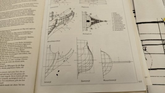
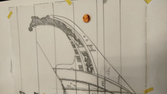
Still dealing with my gallion and it's right placement.
@Ab Hoving @Herman
Have you got any helpfull hint how to place it historically correctly?

Thanks you very much.

View attachment 633553

View attachment 633554

View attachment 633556

View attachment 633557

View attachment 633558

Fantastic work! I’m sorry but I do not have an answer to your question.
However, with all of the brilliant wealth of knowledge in this forum I am sure someone has the answer

Enjoy modeling
 
Hello Follow Modelers,

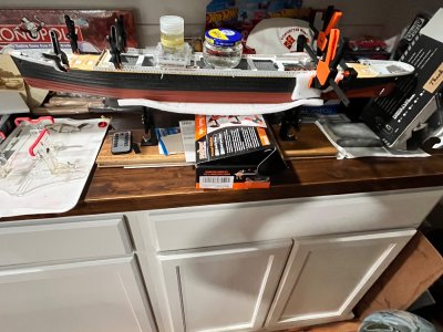
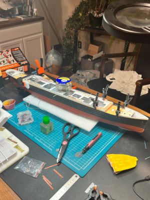
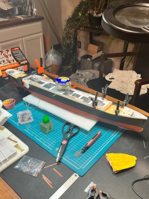
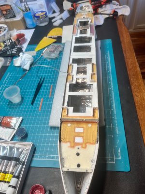
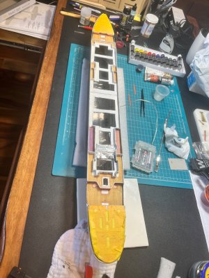
The on-going saga of installing the B/C Deck onto the hull. There are more twists, waves, and bends that I even imagined. I literally have been installing the decks 5 cm at a time. But I believe that I finally got most of it. To tell the truth, frustration was encroaching heavily on me and I contemplated scratch building the hull. The plastic isn’t the best material on the hull and different from the deck plastic.

IMG_3587.jpegIMG_3588.jpeg

That translates to the deck and the hull would not adhering to each other using normal adhesive. The issue is the wooden veneer deck or I would use more aggressive cements. I ended up a combination of E6000 for the overall adhesion, Thin CA for the quick set, and Ultra Thin for the melding. It just took forever because I allowed 16-24 hours of curing before I moved on.

SO….

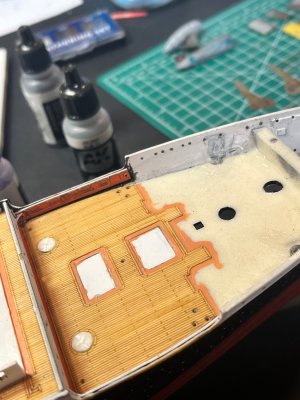
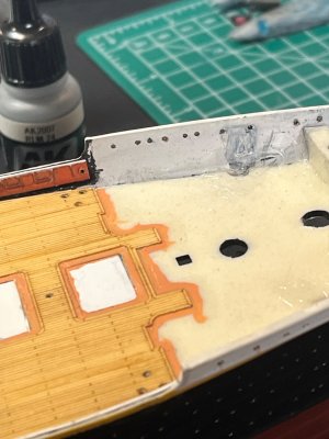
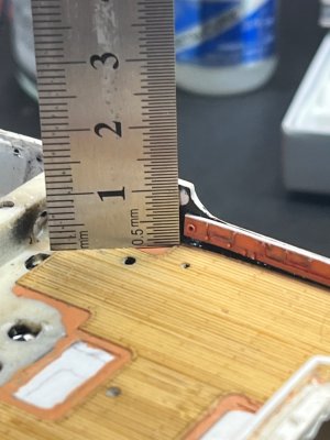
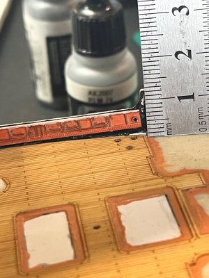
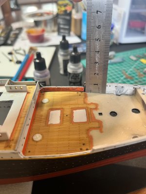
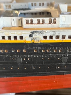
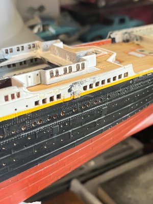
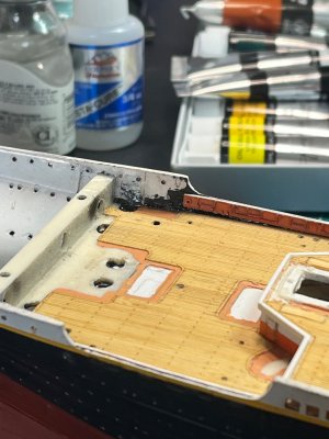
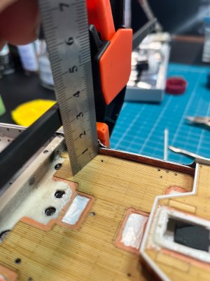
Then I found out the I was over-aggressive in the depth of the decks and lowered one side too much and exposed a gap between the bottom of my bulwarks on the port side.

IMG_3621.jpegIMG_3622.jpegIMG_3623.jpeg

I first thought maybe a length of 0.13 mm thick by 0.25 mm strip along the bottom edge of the bulwark. But the gap was ~ 1.5 mm and too much for the strip.

IMG_3625.jpegIMG_3626.jpeg

That means that I needed to free that side’s bulwark and the deck (specific to that location) carefully wedging a straight shovel blade to separate the parts and re-position the pieces to their correct depth, and re-adhere them without much damage to the existing pieces.

IMG_3627.jpeg

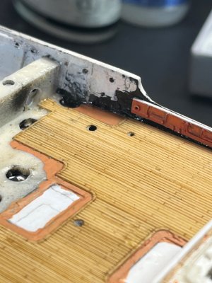
I now found where a gap re-emerged on the port side rear B-deck 2nd class promenade before the bulkhead to the Ala Carte restaurant (I previously glued before multiple times). Possibly from the work on the stern port side bulwark. I used tongue depressors and clamps the get that gap evenly position for a solid gluing surface.

IMG_3638.jpegIMG_3639.jpeg

But I think I it down now (Wipes sweat off forehead). This has taking me about 10 solid days of clamping, gluing, moving, and repeating the process.

I once the deck is solidly adhered, I need to fill in the gaps in between the bulwarks with putty, smooth the top edge of the well deck sheers. I will have a edging piece along the bulwarks for the supporting stanchions that attach to their posts.

IMG_3621.jpeg

Once that section is completed, then I can start correcting and touch-up the areas I manage to mess up. Finally, fitting the next level of decks (A Deck and its structures). There is bulkhead gaps on the forward C Deck bulkhead edges and some on the bulkheads on the forward and stern B Deck promenades.

IMG_3619.jpegIMG_3620.jpegIMG_3609.jpeg

Now that I finally adhere the B/C Decks, I can progress with my population with furniture and “people” in all the promenades and restaurants on B Deck.

IMG_3607.jpegIMG_3606.jpeg

More to come

Happy Modeling - Pete

IMG_3624.jpeg

IMG_3628.jpeg

IMG_3638.jpeg

IMG_3639.jpeg
 
Last edited:
Back
Top