• Ships of Scale has incorportated an extra level of security when you log In. Please follow on-screen prompts to acknowledge that you are not a robot via a "Check Box" or a "Pictorial Check Box Puzzle". This is needed due to higher level of AI Activity Security.
  • SUBSCRIBE TO SHIPS IN SCALE TODAY!

    The beloved Ships in Scale Magazine is back and charting a new course for 2026!
    Discover new skills, new techniques, and new inspirations in every issue.

    NOTE THAT OUR NEXT ISSUE WILL BE July/August 2026
  • Win a Free Custom Engraved Brass Coin!!!
    As a way to introduce our brass coins to the community, we will raffle off a free coin during the month of August. Follow link ABOVE for instructions for entering.

La Belle - CAF Models 1/36 by Signet

Joined
Nov 17, 2021
Messages
1,360
Points
408

Location
Columbia, SC
I've been wondering for quite some time what my next build would be. I wanted a medium size model for which there was an ANCRE or similar monograph for it. I really wanted a "last word" in what the ship should look like. I decided upon La Salamandre, by CAF, which would make a good companion to my CAF HMBV Granado, being a French version of the British bomb vessel. Of course, knowing my timing, the kit was not then available directly from CAF. But Tom at CAF said it would be coming, so I ordered the ANCRE monograph for it. And after the fact, thinking I needed more information about the guns aboard, I also ordered ANCRE's NAVAL ARTILLERY French navy 1650-1850 (never combine shipments for lower shipping cost is my moto).

In the meantime, I pestered Tom about when La Salamandre would be available (sometime soon), and would he please do it in pear wood (no). After a while, he admitted he was spending his time on a new model, a 1/36 scale version of La Salle's ship La Belle (an upgraded and redesigned version of their previous 1/48 scale version). I researched it a bit, and decided to switch gears, to go for the La Belle instead. I reasoned it was a smaller model, but 1/36 scale helped, and Tom said it would include rigging and such. I'm 83years old, and figured/hoped I had one nice ship model left in me, so decided La Belle would be my (probably last) hurrah. Naturally, I bought the monograph (I expect FedEx and ANCRE will both be sending me Christmas cards). Timing of the model was to be June-July. But then it was of course delayed again, and again. Designing a completely new ship model kit is apparently more than a weekend project. :oops: So fine, I researched, and I researched, and I researched. I bought or downloaded every book and document I could find, in addition to the monograph (which I now understand isn't all that accurate), and certainly does not have the detail that La Salamandre does, despite Bourdroit actually being involved in the analysis of La Belle's shipwreck, and never having seen La Salamandre.

The delay gave me a lot of time for research. I started getting confused with information from about a dozen sources, not remembering where facts were, so started a Word document to document facts and information, along with the source of same. It's now about 50 pages long!

Anyhow, come mid-August the kit was finally available for purchase (https://cafmodel.com/product/la-belle-1-36/), along with both good and bad news: The good news was it was available in pearwood (hooray!). The bad was that it was being issued in sections, and Section 1 included only the frame structure. The remainder has been promised for about November. O-kay, not a big deal - I intend to do my very best job on it, it will certainly take me a few months to complete the frame, so I ordered it immediately. In pear. As well as the "matching" Boat-128, also in pear. It was shipped from China on August 15th. And I got it yesterday, September 18. Apparently FedEx (and the Chinese shipper to the US) don't like me all that well after all. Tom says that's waaay longer than normal, but about the same time it took to get my Granada (it's not him, it's not shipping services, it's me, I apparently).

I have to address the cost of the pear wood version of the kit. Most pearwood kits are 10%-20% higher in price than their cherry counterparts. The La Belle is 73% higher! $475 plus shipping versus $275 plus shipping. Is this worth it? I don't think so. But I have no choice - this is my last hurrah ship, and I have no choice other than to spend the money. In retrospect, a better method might have been to get Section 1 in cherry, and the remainder in pear, giving a nice contrast as well as saving money, while keeping the most visible parts in pear. But that's not what I did. Why is pear so expensive from CAF? I know Tom said the shipment they got was very, very nice quality, as well as very, very expensive. This is CAF's first kit in pearwood, so possibly as they make more kits in pear, their costs will go down, and they will be able to lower the price. We will see.

The 1/36 La Belle, despite being 25% larger than the previous CAF kit of the same name, is still a relatively small model: Section 1, bow to stern, is 528mm or about 21". The fully rigged model will be about 24" long and 20" high, a good size for me, I think. And bigger than the Commodore plans on allowing me space for anyhow, so we'll see how that goes.

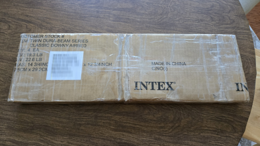
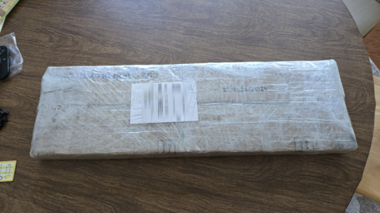
O-kay (that's to prevent the thumbs-up emogi), I will now go immediately to opening the package I received from CAF (apologies to those who read my long novelette above). The package, while quite later than expected, was in excellent condition, and VERY well wrapped:
1789845474594.png
(No, it didn't weigh 22.6 pounds. It weight about 6.5.)
1789845533020.png
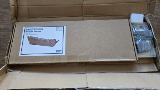
After cutting and unwrapping a layer of bubble wrap and of heavy cardboard, I found:
1789846044927.png
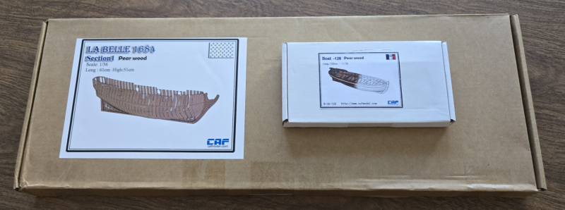
I also ordered the Boat-128. Yeah, in pear.
1789846089987.png
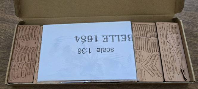
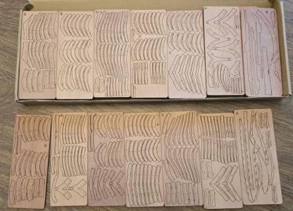
Opening the main Section 1 box:
1789846164228.png
1789846199262.png
1789846242891.png
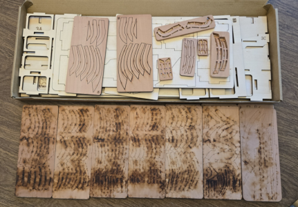
Yeah, some sanding will be required on the back side. Unless I'm able to reverse them, and have the frames char-to-char. I don't know, probably not.

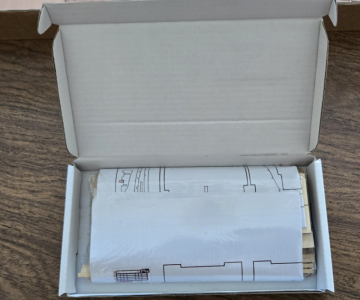
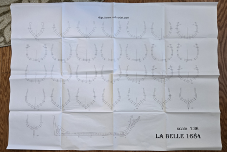
There is one large drawing sheet:
1789846329082.png
I'll have to flatten that some. And a close-up of the keel assembly:
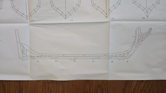
1789846373444.png

Next, looking at the ship's boat:
1789846413585.png
1789846433521.png

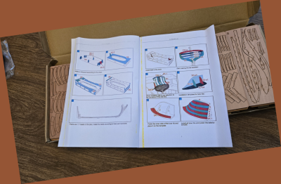
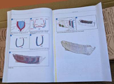
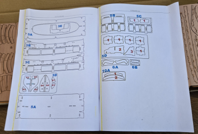
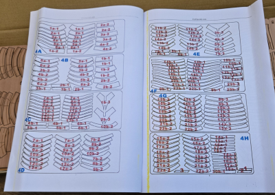
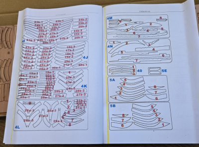
Upon examination, the pear wood all seems quite nice, and fairly consistent in color. The manual is pretty typical and what little text there is in English:
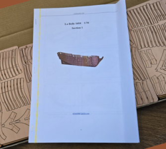
1789846845440.png 1789847020256.png
1789847118817.png 1789847139985.png
1789847172547.png 1789847184676.png
I've just shown the above pages small to get an idea of what the booklet is like, but CAF nicely provides a PDF download for closer viewing.

I think that's about it for my first post. I'll get into some building stuff shortly, but the basic construction shown above is about what we've come to expect from POF kits, and all looks quite nice.
 
Last edited:
I think first I'll write a (very) brief history of the La Belle, and why it's so important:

The explorer La Salle (René Robert Cavelier, Sieur de La Salle) an explorer who had several times been to America, sailing through the Great Lakes that separate the current USA from Canada. He even navigated the Ohio reiver and the Mississippi River all the way to its mouth/delta, near what is now New Orleans, at the Gulf of Mexico. He wanted to find an all-sea route to the delta, to set up a fort and claim this property for France.

He departed La Rochelle, France, in July of 1684, with four ships and over 300 people, in a voyage of both discovery and colonization. The mission was doomed in ways that are hard to imagine. The ketch Saint François was lost to pirates, the storeship Aimable was lost, containing most of their supplies (supplies for both the would-be colonists as well as beads and other trinkets to trade with the local Taensa Indians). He sailed past the Mississippi, never finding it, due to the Gulf's unusual currents. On exploring the coast of what is now Texas, after a time the naval vessel Joly returned to France, having done its duty of escorting (but not protecting) the fleet to the New Land.

Once on the Texas coast, he established a Fort and colony, but still wanted to find the Mississippi. He proceeded on land to find it with a group but along the way was murdered by one of his own men. Meanwhile, the La Belle, his last remaining ship, was told to remain in place. They were not even able to retrieve water from land successfully, having two attempts fail along with the sailor's lives. The La Belle eventually sank in a storm, setting to the bottom in shallow Matagorda Bay, not being found until 1995. While the upper structure was gone, most of the hull was incredibly well preserved, and was excavated using a coffer dam, preserved and relocated, now being on display.

It is considered one of the best preserved shipwrecks of the period, and has told many stories, technical and personal, to those investigating its ruins.

The ship La Belle was a small vessel, considered a Barque Longue, with a keel length of only 45 French feet (48' today) and about 40-50 tons. She had 6 guns, just 3-4 pound in size, and perhaps eight 1-pounder swivel guns. It is rumored she almost made it to the New World in pieces in the hold of one of the larger ships, but was built at the last minute and sailed there instead, being the only ship to survive the failed expedition.

Much has been written about here (I think I've read it all by now), and while there are still many questions and controversies, we know a surprising amount of information about her (which I won't tell you about - you can read that if you like).

To give you an idea of what I will be striving for, here is a photo of one of the many models made based on here discovery:
1789851341147.png

Next time we'll get into construction. I promise!
 
I've realized over the time waiting for the kit to arrive that I have concerns with building Section 1, the frame structure, without drawings or other information concerning the remaining structure. The first thing I do upon the receipt of any kit (or anything requiring assembly, for that matter) is to study ALL of the instructions and plans. Quite often a later step affects current work, and it's difficult, sometimes impossible, to know this ahead of time. Maybe it's my inexperience with ship models in general, plank-on-frame models in particular. I've just never done otherwise. Maybe it's party because during my career I've been involved in writing owner's/user's manuals for quite large and complex equipment.

For example, how much should them stem be tapered, if at all? Boudroit seems to indicate to about 2mm, but is that correct here. How deep, what shape, and in particular, exactly where does the groove for the planking need to be placed? Especially at the stern. That work is FAR easier to accomplish while the keel assembly is still flat. And that's one of the first steps in the structure assembly. Do I allow for framing around the gunports? That kind of thing.

I'm going to see if Tom can help provide some answers for these questions, so I can work on the assembly. And I'm sure SoS forum members will provide information that will help immensely. Certainly, there are some/many U-frames that I could do and set aside. I don't know; I'll have to see.

For now, since I'm anxious, I'm going to work on the ship's boat, a 15' long boat purchased separately in pear wood, and designed especially for this kit, Boat-128. It matches the overall size and configuration of Boudroit's boat drawings included in the La Belle monograph. I'm sorry, because I know many of you are interested in this thread because of the La Belle, not some ship's boat you've probably built a dozen time. Again, I apologize, and hope I can begin work on the frame soon.

[GOD I love this forum! I'd typed the above, and accidentally closed the window, figuring I'd lost all I'd typed, but I opened a different forum view, refreshed, and there it was! Thanks, developers!]

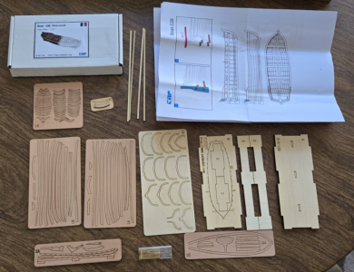
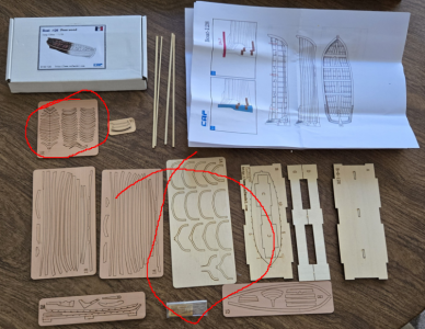
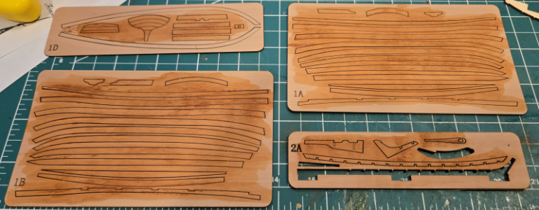
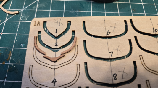
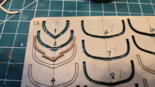
I've only built one "rowboat" before, for my Ragusian Carrack, from Pavel Nikitin, and construction for it was quite different. So I studied the parts included again:
1789865507225.png
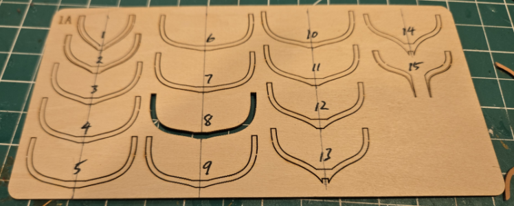
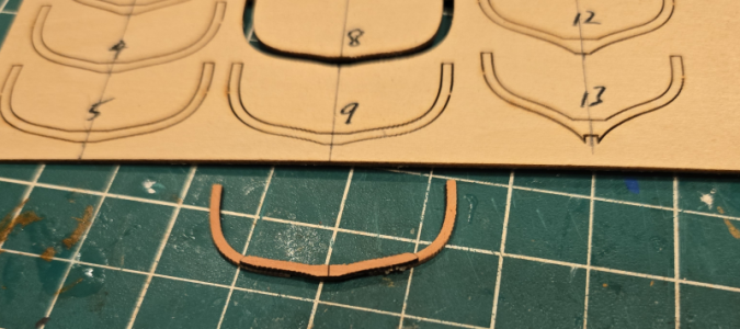
The circled parts are what confused me. The instructions showed 1-piece U-frames, so I figured the lighter colored ones were to be used. I was a bit upset as they weren't pear, then theorized that they'd contrast nicely. Then I found the small parts above left, and realized they were parts of frames. I incorrectly assumed they would be placed end-to-end, with no overlaps or splices, into the voids left by the light-colored U-frames, assuming they would be incredibly fragile (I'd broken many on Pavel's boat). So I copied the two sheets, and cut out pieces to play around.

A few razor cuts of the copy showed that the pearwood frame parts were intended to overlap, by quite some bit, actually, and that each frame was to be made using 3 separate pieces, as shown on Boudriot's drawings in fact. I was a bit disappointed, previously, when I thought the U-frames were a single piece, both because they varied from the published info (such as it is - I realize little published data is 100% accurate on a 300 year old ship), and because the tops would be very weak, being cut cross-grain. So I cut one out for frame 8, the center frame, to try out:
1789866521499.png

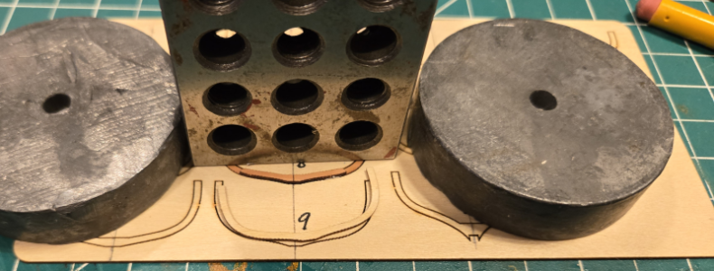
Before cutting and handling the fragile pearwood pieces, I coated them with a coat of thinned shellac (1:4 with denatured alcohol). This soaks into the wood fibers, making it stronger, but does not change the appearance of glue-ability.

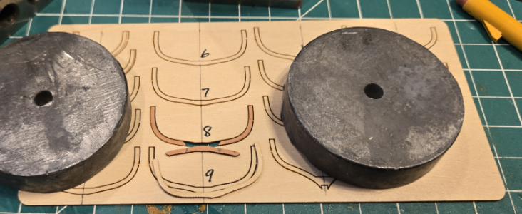
Then placed the upper parts in place, firmly against the top of the 'U':
1789866544258.png
The lower piece spans the gap, overlapping for strength:
1789866624838.png
Marks on the lower piece show where I need to put the glue (Ponal Express).

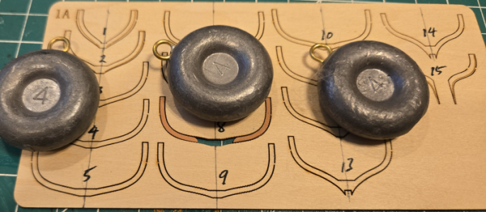
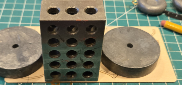
I positioned a heavy, flat weight to keep the upper arms in place, while acting as a stop to locate the lower piece.
1789866728430.png
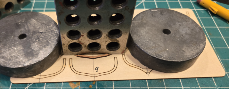
I added the removed U-shaped form to stabilize a weight on the lower portion:
1789866821101.png
And another weight to hold in in place while the glue sets:
1789866891223.png
The result is that while the material is only 1mm thick, the assembly is quite strong, since the grain is oriented properly, and the design matches that drawn by Boudroit.
1789866962459.png
I left the char on at this point, only removing it from the inside with a rotary drum at low speed, and manually from the outside.

I realize the above steps are no doubt published in both Model Shipbuilding 101 and Shipbuilding for Dummies, but since none of this is shown in the instructions, I thought I'd include them.

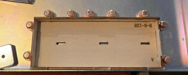
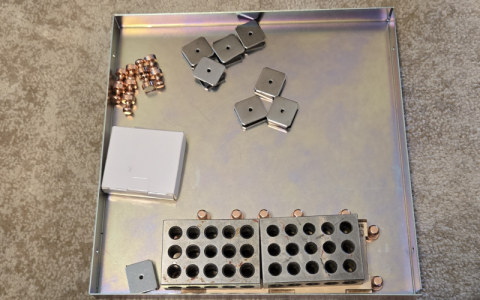
I assembled the assembly jig. I used a metal frame with magnets I'd purchased; with stronger magnets, it works pretty well.
1789867796605.png
1789867808911.png

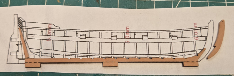
I then went to the keel assembly, and compared it against the drawings in the instructions:
1789867880977.png
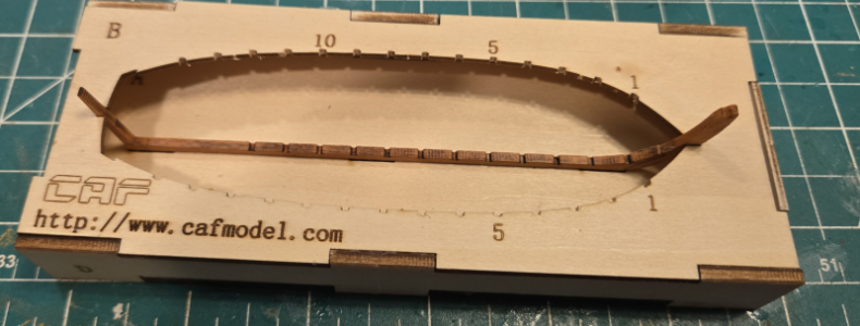
The keel appeared to be short by about 5 mm. But after comparing the slots in the jig, it is correct. The drawings are just a bit oversize. So while the drawings are very good, don't depend on them for actual measurements. As you can see, the keel assembly fits quite well into the jig:
1789868096327.png

I took a few moments to put a thinned shellac coat on both sides of parts I would be using later. Here, I've added leather stain to the shellac coat to stain the pear a darker color. Again, this has penetrated and strengthened the wood, does not cover the grain, and will not affect its ability to be glued nor to accept a finish coat (to be determined, but probably rub-on poly).
1789868331211.png

Continuing on, the transom, part 1D-2, must be bend to match the transom seat:
1789869292678.png
1789869315816.png
And then positioned:
1789869353286.png
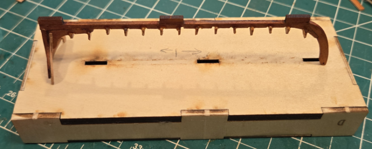
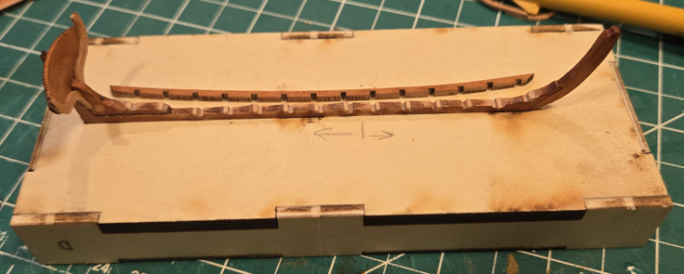
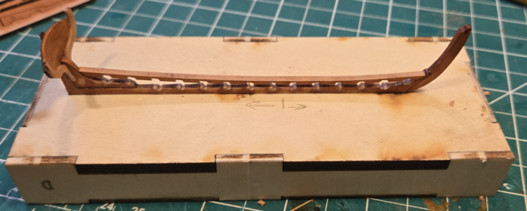
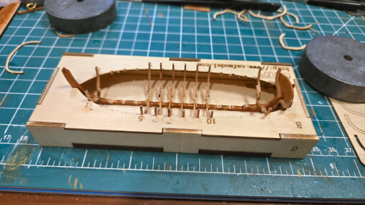
The boat assembly thus far (frames are just set in place):
1789869391811.png
The frames appear to be leaning a bit toward the front of the boat. This is controlled by the position of the keel, the position of the slots (both determined by the jib) and the offset in the 3-piece frames. Here I've inserted a cut-out U-section for comparison, which of course has no offset.
1789869641400.png
It looks to me like the jig was designed for single-piece U-shaped frames as shown on the instructions, not the pearwood 3-piece frames which have an offset due to the bottom piece. I feel this is an error, probably due to adding the 3-piece frames for more strength and authenticity after the jig design was finalized. I'm not sure how I'll handle this, as I definitely prefer the 30 pieces. If the slope is not too bad, I may leave it. If it is too noticeable, I'll have to elongate the notches in the jig to properly position the frames vertically.

That's it for my first day. This one has been longer than most, but I'll try to keep a good pace of construction going on. Thanks for the comments and likes! :)
 
Last edited:
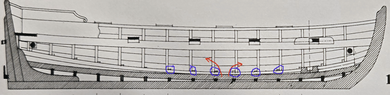
Concerning the offset of the floor with the sides of the three-piece U-frames mentioned above, these drawings show the offsets clearly:
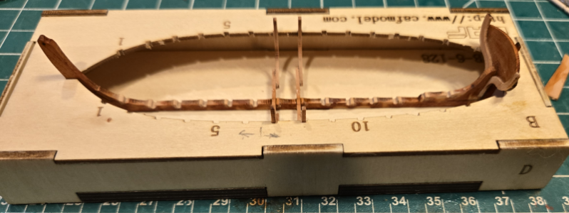
1789955681341.png
1789955701870.png
The side members are attached to the fore-side of the floor members from frame 6 onwards, and to the aft side from frame 7 back. The side portions of the U's are evenly spaced, but that means that the slots in the keel are offset by the material thickness, either to the fore or the aft, matching the above diagram. If the light wood single-piece frames are used, then there is no problem, and they fit in place with the keel notches matching the slots in the jig.

But I wanted to make them in 3 pieces, as I think portions of the bottom parts will show, and I want it to look right. I hated to start rationalizing an easier and less-accurate construction method for the first part of my great last "hurrah". That would be quite disappointing, I think.

I needed to move the notches for the frames in the keel over by 1mm to have the upper portion of the frame match the jig slots. Of course, I can't move them. And I don't have the material, patience or skill to manufacture a new keel (yeah, I know, many of you would have). My solution was to widen the slots from 1 to 2 mm, widened on the side of the lower portion of the frame, and then fill the opening to better capture the frame and make it stronger. Do do this, I first cut with an Xacto blade notches 1mm to the side of the existing notches, and dig a bit of the intervening material out. I then used a file, which happened to be exactly 2mm thick at one side, to widen the notches.
1789956820044.png
The jig worked out great for this process, turned upside-down. ;-)
1789956928106.png
1789956961767.png
1789956993604.png
1789957025012.png

I then cut small pieces of 1mm material to fill the areas to the side opposite the bottom of the frame, and larger pieces to be surrogate frame, glueing each small scrap in place:
1789957121385.png
And then I'll cut, filled and re-slotted all the slots, in effect moving them:
1789957217305.png
Yes, I've made an elegant keel ugly. But it will be covered. (First stages of rationalization.)

The keel is now modified, and now I realize the keelson is wrong (duh!) and the slots need modified here as well:
1789957413189.png
I decided to simply extend the slots in the keelson to fit over the frames. (Second stage of rationalization. I think I'm in trouble.)
1789957511012.png

Returning the keel assembly to the correct side of the frame, I tested the fit of the two frames made thus far, with the keelson:
1789957611363.png
I think that's what I'm going for. A check of the frames:
1789957674596.png
They look to be square and vertical, as they should be. Or at least as close as they will get. I'll now take some time making and fitting the remaining 12 frames.
 
Continuing on with making and installing the frames, there's something you need to watch out for, if you're using the pearwood 3-piece frames. The method I used to assemble the frames, as shown above, was to place the upper side portions of the frames in place, then add the bottom portion on top and aligned with these. I've been placing the "top" of all frame sheet pieces up, so that the bottom portion, which has a vertical centerline in it, can be used to center the frame in the jig, as shown below:
1790041842905.png
You will notice above that the pieces also have the lines used to bevel the edges to conform to the hull shape. The problem is, if you place the sides into the opening, then add the center/bottom piece, and glue up the assembly, when placed into the jig, the bevels will be on the wrong side (in this case, the back side), when they must be beveled on the fore side. The solution (or at least one of them) is to place the side pieces back-side-up, then the bottom atop them. Then, when placed properly into the jig (frames 1-6 have the outer side parts facing forwards, 7-15 aft:
1790042114606.png
I chose to keep the center piece facing upwards because I used the centerline to help center the frame. It won't really be visible, and the bevel lines on the center frame don't really apply, because that portion is no longer at the frame location.

This is where I am so far. Only 1 frame broken so far (#1), and that's because it stuck in the template sheet, and I was too anxious to properly un-stick it.
1790042280669.png

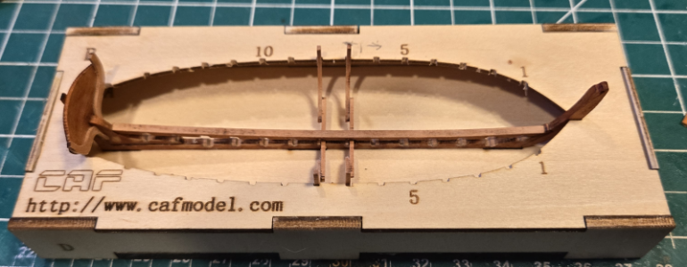
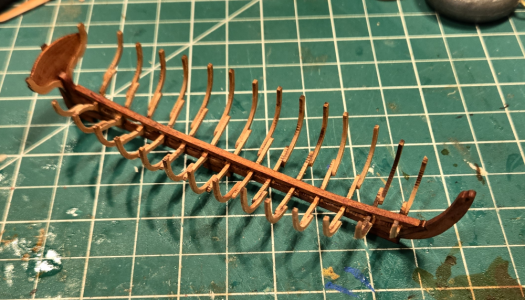
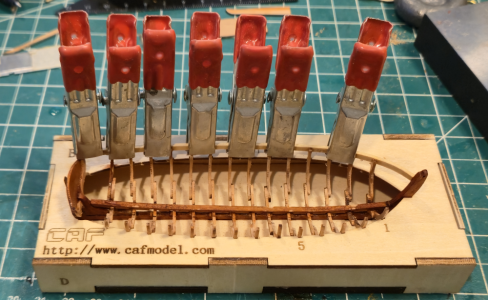
The last ribs go in place:
1790131497591.png

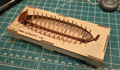
And, without the jig we have:
1790131528484.png

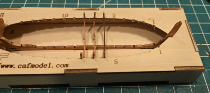
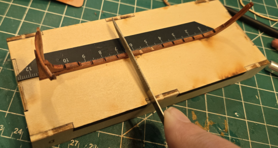
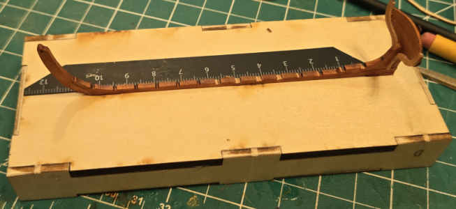
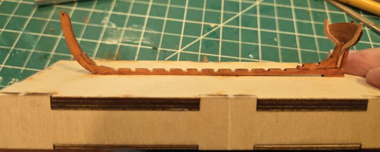
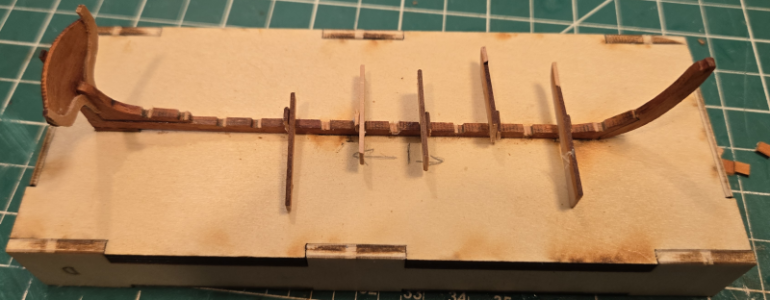
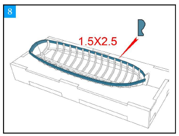
Now I have to making the surrounding 1.5 x 2.5mm strip into a moulding, using one of those razor-blade-type thingies I have left over from another build. One is not supplied with this kit; I guess they figure you'll use the one for the main boat. I haven't had much luck making these, in fact I've never been able to make one acceptable enough to use on a kit. Here's hoping for a first time.
 
You are doing a great job with this project. Well done.
Thanks, Bryan. The good news is that I am pretty clear now on the questions I had concerning Section 1, the frame. Between Tom's help, eureka moments when taking a closer look at the included parts, Boudroit's information and some hopefully-logical assumptions, I feel I'm good to go on the main ship. I know new viewers here, expecting to see the new La Belle build, are greatly disappointed to see a rowboat. I don't want to leave Boat-128 in too many pieces, but I may start the main La Belle structure before finishing the boat. Fairly soon, in any event.
 
Now to make moldings from the 1.5x2.5mm strips included (not pear, but I'm painting them, so...). I've NEVER been able to make a molding using the razor-blade like pieces of (I think) stainless steel included with various kits.
1790217750918.png
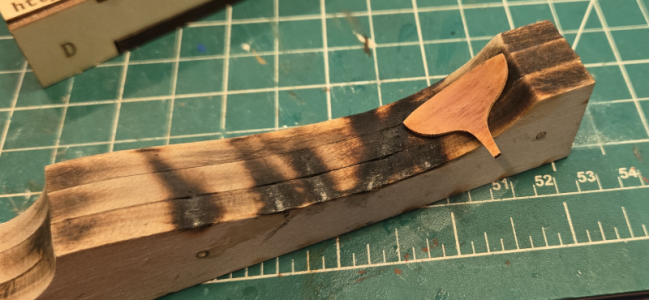
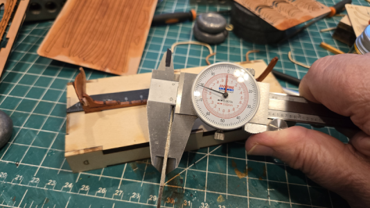
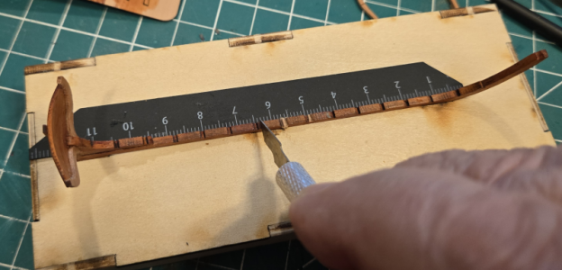
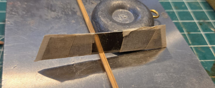
This kit didn't include one, but I tried one I had on hand. While I'd failed with ship-length strips, I thought I might do better with a 5" rowboat. WRONG! It took forever, and did little except bend and dull the stainless piece. I'd read (of course) that people used razor blades to make their own, and while I felt this would be beyond my abilities, I thought I'd give it a try. I'd just bought some large razor knives for replacement in an old Craftsman Handi-Cut I've had for probably, heck, I don't know how many years. It took me 5 tries to get a profile that matched the 2.5mm width (critical - too wide and it wanders, too narrow and it binds). The profile wasn't the problem, the width was. Anyhow, I finally got one cut I was happy with, and It WORKS. Night - And - Day, compared to the ones included with kits. I presume because the SS they use isn't hardened, whereas this knife blade certain it. I added a bit of tape, to cover the wrong cuts as well as to protect my fingers, and it did great:
1790218164515.png
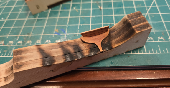
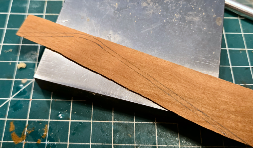
I'm not sure what I'm going to do for the stern piece shown made of the same material. I tried bending a molded piece, and almost got it bend the stiff way, but it kept buckling the other direction, where I need it bent in two dimension. It ended up breaking. I then took a piece of scrap wood, laid out the curve I needed for one direction, with straight pieces either side, and went to work molding it:
1790218358327.png
It ALMOST worked, but in the end broke before being bent to the other direction.

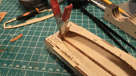
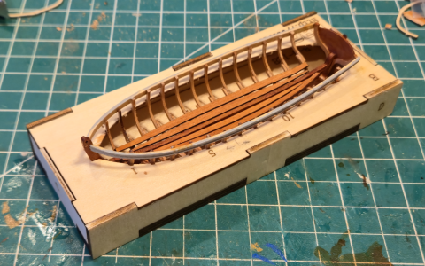
So for now, I'm leaving it off, and may end up with a different stern arrangement. Anyhow, I then heat-bent, glued and clamped the pieces made above around the boat's top rail area (Yeah, I'm a plethora of nautical terms):
1790218469739.png

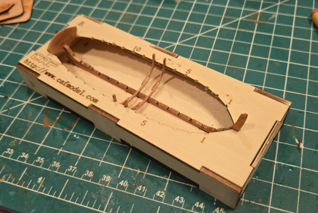
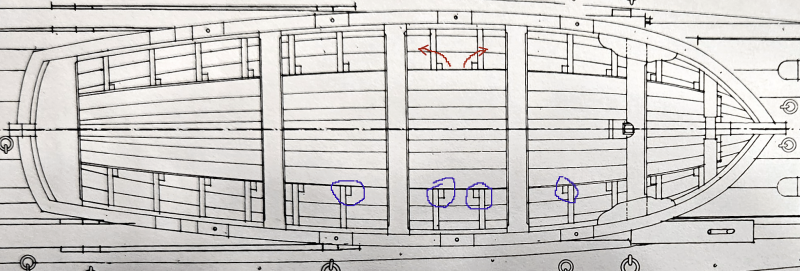
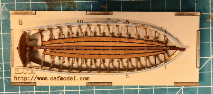
I didn't have the right color paint for these strips, so for now primed them with some light gray. I then placed the floor-boards into the boat, separating them as I've seen done elsewhere. Neither CAF nor Boudroit showed them that way, but CAF had 2 planks each side, Boudroit 3 planks, so this gave me closer to the with shown by Boudroit.
1790218633656.png
The spacing between the planks isn't as uneven as it looks above, due to the angle distortion. When viewed from above, they're fairly close:
1790218831325.png

I intend to finish paint the molded rails before proceeding with the top rail or planking, and it will take about a week to get the paint. Working on other parts, I ruined the rudder (I think - the belt sander I was using to taper the thickness pinched it between the belt and the bed, made nasty snapping sounds, and sent it to oblivion. A new one was traced and made with slightly thinner sheet, so I'll add it later.
 
This looks like a fine kit and I love your work! Although small, it seems to be well thought out and of nice quality. I'll continue to watch your progress.
 
Back
Top