• Ships of Scale has incorportated an extra level of security when you log In. Please follow on-screen prompts to acknowledge that you are not a robot via a "Check Box" or a "Pictorial Check Box Puzzle". This is needed due to higher level of AI Activity Security.
  • SUBSCRIBE TO SHIPS IN SCALE TODAY!

    The beloved Ships in Scale Magazine is back and charting a new course for 2026!
    Discover new skills, new techniques, and new inspirations in every issue.

    NOTE THAT OUR NEXT ISSUE WILL BE July/August 2026
  • Win a Free Custom Engraved Brass Coin!!!
    As a way to introduce our brass coins to the community, we will raffle off a free coin during the month of August. Follow link ABOVE for instructions for entering.

What Is This?

Joined
Nov 17, 2021
Messages
1,372
Points
408

Location
Columbia, SC
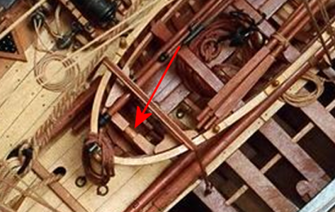
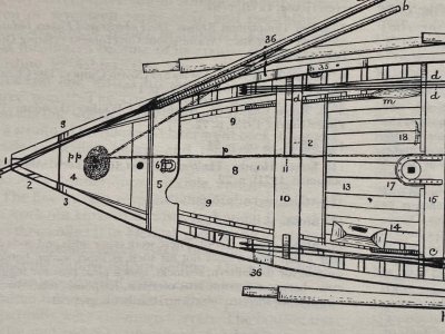
I've seen photos of models with this in them, and drawings as well (near both the fore and aft ends of ship's boats), but don't know what they are.
1790480933228.png
Google AI says it's used for towing (with a couple possible titles), but I fail to understand how. Any info and/or references would be appreciated.
 
I've seen photos of models with this in them, and drawings as well (near both the fore and aft ends of ship's boats), but don't know what they are.
View attachment 639337
Google AI says it's used for towing (with a couple possible titles), but I fail to understand how. Any info and/or references would be appreciated.
Looks like a windlass to me. Used to haul anchors and tighten lines.
At least, that’s my guess.
Thanks,

Harvey
 

View attachment 639434
Does your document describe what that fixure is for?
My guess woud be a fair lead of some sort. It shows no mechanism to serve as a windless.
I have not seen that on English long boats, in drawings, plans or models.

1790528977601.png

A windlass would tend to be mounted more mid-ship.
 
Hmm. Doesn't look like it would be used for handling anchor rodes or such because there are no fairleads or chocks in the area. It could be used for hauling the boat since it's near the bow and has a rounded center section which would serve to keep the line centered. However, that would lead you to expect something similar at the stern. Is there anything similar at the stern? Fair winds!
 
Hmm. Doesn't look like it would be used for handling anchor rodes or such because there are no fairleads or chocks in the area. It could be used for hauling the boat since it's near the bow and has a rounded center section which would serve to keep the line centered. However, that would lead you to expect something similar at the stern. Is there anything similar at the stern? Fair winds!
Yes, there is one of these constructs at each end. AI seems to indicate they were used for pulling ropes and such, but I would think that would require a lead or some such (similar to a hawsehole, but could be open-topped). Without that, ropes at an angle would wear against the wale, and move around.
 

View attachment 639434
Thank you for that. A very interesting conversation at that thread.

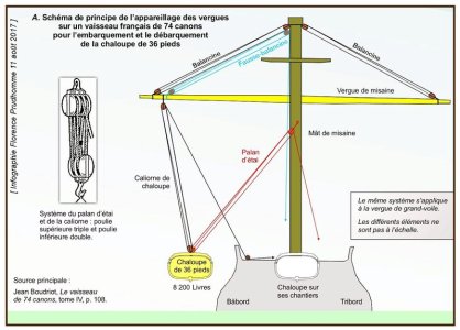
However, if you/they are indicating that during transfer of the boat from the deck to the water, the lifts are connected to the central round portion of this structure, that doesn't make sense to me. A simple hook or loop attached to the top of the keel structure seems better. The structure we're talking about here is intentionally mounted low, and that would/could make the boat tilt to the side, and the design of the structure, allowing it to slide, would make it worse. It seems it's designed for a lot more than just lifting the boat, and designed poorly for the simple task of lifting.
 
Some of the larger boats were used to haul anchors that were stuck in the sea floor. At the bow OR stern - depending on the country - the devise could lead a rope from the rail and lead it to the windlass by running just above the floorboards. BUT with no evident structure to get the rope over the rail and being at both ends - I would rule out that use.

The boat has a sail. This could be used to secure the fore stay at the bow and back stay aft. It may make it easy to adjust the angle when stunt sailing. I have no experience with sailing so I do not know if some lateral play is a good thing. It would not be prone to jam or hinder the movement of the stay.
 
Thank you for that. A very interesting conversation at that thread.

However, if you/they are indicating that during transfer of the boat from the deck to the water, the lifts are connected to the central round portion of this structure, that doesn't make sense to me. A simple hook or loop attached to the top of the keel structure seems better. The structure we're talking about here is intentionally mounted low, and that would/could make the boat tilt to the side, and the design of the structure, allowing it to slide, would make it worse. It seems it's designed for a lot more than just lifting the boat, and designed poorly for the simple task of lifting.
This document runs to several pages, it suggests that a secondary side line was also used to protect boat.
z1_cha13.jpg
Does your document describe what that fixure is for?
My guess woud be a fair lead of some sort. It shows no mechanism to serve as a windless.
I have not seen that on English long boats, in drawings, plans or models.

View attachment 639462

A windlass would tend to be mounted more mid-ship.
Typically, any windlass could serve as a capstan or be used for towing, hauling sails, or handling the anchor.
 
However, if you/they are indicating that during transfer of the boat from the deck to the water, the lifts are connected to the central round portion of this structure, that doesn't make sense to me. A simple hook or loop attached to the top of the keel structure seems better. The structure we're talking about here is intentionally mounted low, and that would/could make the boat tilt to the side, and the design of the structure, allowing it to slide, would make it worse. It seems it's designed for a lot more than just lifting the boat, and designed poorly for the simple task of lifting.
Cap'n Signet:
Your reasoning is sound but a hook or loop on the keel would be even lower and increase the risk of the boat heeling in the lifts. What would make sense is a "toggle or iron strap" as shown as item no. 6 in the drawing below, This is a drawing of a 19th century American whaleboat from The Whaleboat by Willits Ansel. However, there is no such hardware shown in either the photo in post #1 or the drawing in post #3. I admit that a whaleboat would likely have been lighter than the ship's boat under discussion. This remains a bit of a head-scratcher.
Fair winds!

whaleboat bow.jpeg
 
Longboats and later, Launches were fitted with rollers at bow, stern, and sometimes both. The location depended on how the anchor was handled. Brudroit (sp?) writes that location of these rollers depended on how the anchor was handled. British longboats hauled from the bow, French longboats over the Stern, and when the British adopted the launch they hauled over the stern too. I don’t believe though that this is one of these rollers as they were much smaller, at the level of the gunwale, and handled a much smaller messenger line not the cable itself. It might be somehow be involved with handling the much larger anchor cable as it came aboard.

Likewise, I don’t believe that it was used to hoist the boat in and out of the water. Hooks and ringbolts were used for this. Launching a small boat from a large vessel could be a hazardous undertaking. It required detaching the boat from the falls as soon as soon as
it became buoyant. The difficulty of doing this with both ship and boat rolling and plunging in a seaway is evident from the many patented devices for disconnecting boat falls developed in the late 1800’s. Anyone who has tried to untie a knot in a wet line under tension will understand this.

Roger

 
Cap'n Signet:
Your reasoning is sound but a hook or loop on the keel would be even lower and increase the risk of the boat heeling in the lifts.
I meant at the top of the bow, which the keel extends into. Sorry, I don't know the terminology, especially since this is a small boat, not a ship. On the model I'm making, I simply drilled a hole at the top of this area, above the rail. I don't see a similar location to use at the stern, though.
What would make sense is a "toggle or iron strap" as shown as item no. 6 in the drawing below, This is a drawing of a 19th century American whaleboat from The Whaleboat by Willits Ansel. However, there is no such hardware shown in either the photo in post #1 or the drawing in post #3.
I agree, no. 6 would work great. Possibly for rigging too.
I admit that a whaleboat would likely have been lighter than the ship's boat under discussion.
While I've seen these "spool things" on 30'+ boats, mine is only 14-15' and Boudroit still shows them.
This remains a bit of a head-scratcher.
Google AI calls them fairlead rollers or bollards, but when I search for those items, I don't find anything that looks like this, or seems to serve the same function.
 
Cap'n Signet:
Your reasoning is sound but a hook or loop on the keel would be even lower and increase the risk of the boat heeling in the lifts. What would make sense is a "toggle or iron strap" as shown as item no. 6 in the drawing below, This is a drawing of a 19th century American whaleboat from The Whaleboat by Willits Ansel. However, there is no such hardware shown in either the photo in post #1 or the drawing in post #3. I admit that a whaleboat would likely have been lighter than the ship's boat under discussion. This remains a bit of a head-scratcher.
Fair winds!

View attachment 639503
This is not related to the sail rigging. This fitting is also found on heavy longboats. Bear in mind that it is a French boat—technically much more complex.


Longboats and later, Launches were fitted with rollers at bow, stern, and sometimes both. The location depended on how the anchor was handled. Brudroit (sp?) writes that location of these rollers depended on how the anchor was handled. British longboats hauled from the bow, French longboats over the Stern, and when the British adopted the launch they hauled over the stern too. I don’t believe though that this is one of these rollers as they were much smaller, at the level of the gunwale, and handled a much smaller messenger line not the cable itself. It might be somehow be involved with handling the much larger anchor cable as it came aboard.

Likewise, I don’t believe that it was used to hoist the boat in and out of the water. Hooks and ringbolts were used for this. Launching a small boat from a large vessel could be a hazardous undertaking. It required detaching the boat from the falls as soon as soon as
it became buoyant. The difficulty of doing this with both ship and boat rolling and plunging in a seaway is evident from the many patented devices for disconnecting boat falls developed in the late 1800’s. Anyone who has tried to untie a knot in a wet line under tension will understand this.

Roger

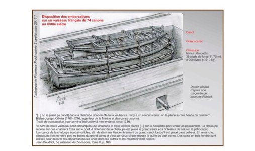
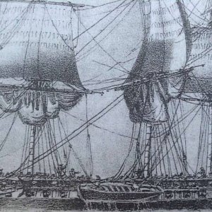
French boats were stacked on top of each other. Look at this Roger. Idk.
utilis11.jpgimage210.jpg
 
I meant at the top of the bow, which the keel extends into. Sorry, I don't know the terminology, especially since this is a small boat, not a ship. On the model I'm making, I simply drilled a hole at the top of this area, above the rail.
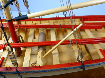
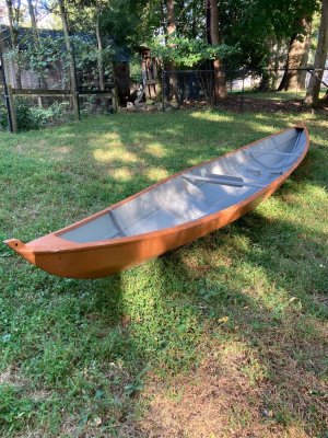
It's called the stemhead. A hole there is pretty common on small boats. One is shown in the photo. In the interest of full disclosure, the hole you can see is in the stern post since this is a double-ender. Fair winds!

tursi 16.jpeg
 
All very interesting, and seemingly documented if only I could interpret the French, and the Accumulated Idiocy could manage translation of specialised jargon.
The drawings I have seen show a very sturdy fitting built in to the hull, apparently to allow considerable force or weight to be transmitted. Hence the suggestions about anchors. My first thought was that it would be related to towing, built to take sudden shock forces and dissipate them into the major hull structure of the keel without damage. The photo of a bored stemhead does not do this job - though for the weight of the boat shown, it is adequate, for a loaded ships boat the stem would disintegrate when a couple of tons is applied to a rope, or a metal hook in that configuration.
The diagrams of how the boat is rigged for launching over the side seems to be likely. The weight of the boat is handled, and as someone mentioned, a quick release loop would do the job of launch / retrieval. The main problem being that the attachment is so low that there could be a risk of instability which would have to be mitigated by additional lines.

Have we any experts in French rigs on the list? Surely there must be plenty of expertise dans La France?

J
 
All very interesting, and seemingly documented if only I could interpret the French, and the Accumulated Idiocy could manage translation of specialised jargon.
I've used Google translate on the entire thread referenced above. It is all about the rigging from the masts and spars used to lift the boat, not the connections at the boat, despite the diagram above.
The drawings I have seen show a very sturdy fitting built in to the hull, apparently to allow considerable force or weight to be transmitted. Hence the suggestions about anchors. My first thought was that it would be related to towing, built to take sudden shock forces and dissipate them into the major hull structure of the keel without damage. The photo of a bored stemhead does not do this job - though for the weight of the boat shown, it is adequate, for a loaded ships boat the stem would disintegrate when a couple of tons is applied to a rope, or a metal hook in that configuration.
Plus I can't see how a cable, say for an anchor, around the item in question could be lead over the rail and into the water without causing damage to the rail and/or cable. Some larger boats I've seen have a roller at the stem for this, so for it, it would mam
The diagrams of how the boat is rigged for launching over the side seems to be likely. The weight of the boat is handled, and as someone mentioned, a quick release loop would do the job of launch / retrieval. The main problem being that the attachment is so low that there could be a risk of instability which would have to be mitigated by additional lines.
My thoughts exactly. Plus a loop around the round portion would slide back and forth, adding to that instability.

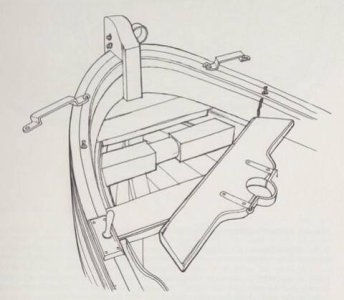
I showed the above picture to Google AI, and this is what it came up with:

The shaded block shown in your diagram is a fairlead roller assembly (specifically the solid wooden frame or structural block housing the horizontal rollers, which on 17th-century French ship's boats is referred to as a traversin à rouleau or traversin de rollon).

Anatomy and Purpose:

  • The Shape and Mounting: These heavy square wooden blocks are solidly bolted athwartships (cross-wise) directly onto the boat's internal frame timbers at both the bow and the stern. The center portion is turned or cut down into a rounded profile to act as a smooth, heavy-duty rolling pin or bearing surface.
  • Why There is No Moving Mechanism: In classic 17th-century French small craft design (like a chaloupe or canot), these were often constructed directly as static, heavily rounded wooden cross-beams rather than true multi-part mechanical pulleys to ensure they could withstand immense stress without cracking.
  • The Primary Function: These assemblies served as heavy-duty guides for anchor cables, messenger lines, and towing warps. When the ship's boat was deployed to drop or weigh a heavy iron kedge/stream anchor, or when the boat was being towed behind a larger man-of-war, the massive ropes were led directly across this rounded portion. This layout effectively centered the pulling force along the keel line to prevent the boat from capsizing sideways, while the smooth curve prevented the heavily tensioned ropes from chafing or cutting through the thin wood of the gunwales.
(And I had to re-ask several times, as previous explanations were obvious spurious.) That almost make sense, but I don't see any protection for the gunwales. Cables wrapped around the roller have to go over the gunwale and into the sea, resulting in much force and wearing on the gunwale, exactly what the description above says they prevent.
 
Whatever it is, the English seemed to have done well without it, and they were pretty good at adapting ( or ignoring) good ideas from various sources.
 
Back
Top