Hi Guys,
Well I have actually made a start on The Hayling Hoy. I purchased the book from Seawatch last month and have been going over the drawings and planning the build. I have made a start and have begun documenting the process, mostly because I will more than likely require assistance along the way.
The first issue I came across was not wanting to damage the original drawings that came with the book. As I have a large format printer for architectural work it was a matter of scanning the large sheets and getting copies made. The issue I had was my scanner is just a A4 job. I began scanning the documents in section and used the automate photo merge function in Photoshop CS, brilliant tool which makes perfect alignment of the documents.

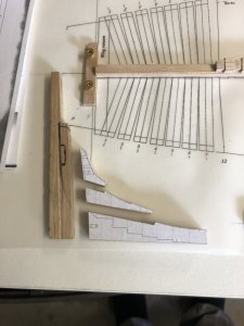
Here you can see the merge is flawless and after measuring the originals with calipers its good to go.

Here I was getting ready to start cutting out the shapes for the templates which will be used on Oak for all the structural members of the build.

This build so far uses a simplified scarph joint which suits me fine for my first whole scratch built model. I had to measure some dimensions in metric and I also needed to study the sections to ascertain how this all goes together. Along with this I needed to figure out the exact terminology. Slowly getting there.

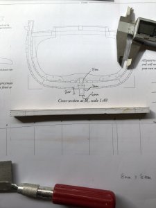
On the image below and the area circled is where I had a little dilemma to start with. You can see above the keel a smaller part which I originally thought was part of the keel.

After attempting to manufacture the keel and not knowing the rising wood was seperate, I ended up with a combined rising wood/keel peice.


Well after finishing up I found a great article on ship construction and scrapped the piece in order to construct it correctly.

After sorting through that issue I started to get serious with the setup and proceeded to setup the building board braces and pieces to lock the keel into position. Whilst building the keel I went for the option of placing some black card stock into the join to simulate the tar. Works pretty well I think.


So there we have it for now, so far so good. The next challenge is to sort out the keel rabbit, I think I might make a steel template and use it as a scraper. I will think more on this as it might just be quicker to use the trusty ole chisel as I dont have a v gauge. Maybe I should buy one as there will be many more scratch build in the future.
Thanks for stopping in guys.
Steve
Well I have actually made a start on The Hayling Hoy. I purchased the book from Seawatch last month and have been going over the drawings and planning the build. I have made a start and have begun documenting the process, mostly because I will more than likely require assistance along the way.
The first issue I came across was not wanting to damage the original drawings that came with the book. As I have a large format printer for architectural work it was a matter of scanning the large sheets and getting copies made. The issue I had was my scanner is just a A4 job. I began scanning the documents in section and used the automate photo merge function in Photoshop CS, brilliant tool which makes perfect alignment of the documents.
Here you can see the merge is flawless and after measuring the originals with calipers its good to go.
Here I was getting ready to start cutting out the shapes for the templates which will be used on Oak for all the structural members of the build.
This build so far uses a simplified scarph joint which suits me fine for my first whole scratch built model. I had to measure some dimensions in metric and I also needed to study the sections to ascertain how this all goes together. Along with this I needed to figure out the exact terminology. Slowly getting there.
On the image below and the area circled is where I had a little dilemma to start with. You can see above the keel a smaller part which I originally thought was part of the keel.
After attempting to manufacture the keel and not knowing the rising wood was seperate, I ended up with a combined rising wood/keel peice.
Well after finishing up I found a great article on ship construction and scrapped the piece in order to construct it correctly.
After sorting through that issue I started to get serious with the setup and proceeded to setup the building board braces and pieces to lock the keel into position. Whilst building the keel I went for the option of placing some black card stock into the join to simulate the tar. Works pretty well I think.
So there we have it for now, so far so good. The next challenge is to sort out the keel rabbit, I think I might make a steel template and use it as a scraper. I will think more on this as it might just be quicker to use the trusty ole chisel as I dont have a v gauge. Maybe I should buy one as there will be many more scratch build in the future.
Thanks for stopping in guys.
Steve

")