BALDER, Vlaardingen Herring Lugger from 1912, scratch build scale 1:50 Plate-On-Frame

I like the second version of hinges better... I didn't realize you have such big fingers... ;)
1:1 fingers vs 1:50 tiny hatch.....no contest ROTF.

Good morning Peter. I liked your first hinges, however you are never satisfied with "like". I'm with the other guys, these are now in the category of "Peters satisfaction" which is brilliant. The hatch is a fantastic 1:50 scale of the real thing. Cheers Grant
Thanks, Grant. My visit last week to the original Balder it became clear how to make the hinges more in shape. I had already partly applied the method of making it to the 1st version, but the copper foil was too thin for this. But this will certainly remain applicable for 'normal small hinges'.
Regards, Peter
 
Not much to report. Only that I can now apply a different method to the port side part.
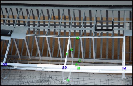
First the overview picture:
0453 BB-23.jpg
Zoomed in:
0454 BB-23.jpg
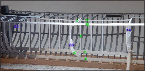
I had already made the keel beam 'A' and side stringer plates 'B' to size.
The keelson 'C' and middle longitudinal beam 'D' also sized.
I could now place the watertight bulkhead '14' on the keel beam 'A', align it on the starboard part and secure it under the side stringer 'B' and set it at a distance with the keelson 'C' and middle profile 'D'.
Then the 8 double U-profile supports 'E' were made to size and glued between the keelson 'C' and the middle beam 'D'.
Halfway the open part, the deck beam and frame '23' were made and glued in position.

From a slightly lower position:
0455 BB-23.jpg
Zoomed in:
0456 BB-23.jpg
With the same letters and number as before.
In this way I have again created the necessary strength to be able to place all the following parts properly.

Now to work on the deck beam/frames '19' and '29' so that I can then make the bilge stringer to size and shape. That will then help me to neatly align the other frames so that I get a smooth progression to be able to apply tight skin plates later.

Again, always thinking a few steps ahead.;)
Regards, Peter
 
Last edited:
After placing frames 19, 23 and 29 I could make the bilge stringer.
As explained when making the starboard side, this has a double curve. One following the hull line and one with the ends running upwards.
The latter depends on the shape of the outside of the frames, because the bilge stringer is between the 5th and 6th barrel:
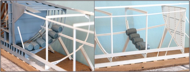
0457 Kimweger.jpg
At the largest width of the hull the frame is flatter at the bottom. Further back the frames become increasingly slanted. The distance projected over that shape between the 5th and 6th ton must be the same everywhere.

After fitting, measuring and bending into shape I could apply it:
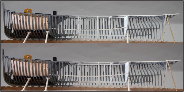
0458 Kimweger.jpg
I photographed the model twice, with a small position shift.
In the top photo the grey starboard bilge stringer is just above the white one on the port side. In the bottom photo he has almost completely disappeared behind it. The shape of both is almost the same.

It is also now very fun to play with the different curves in terms of photography:
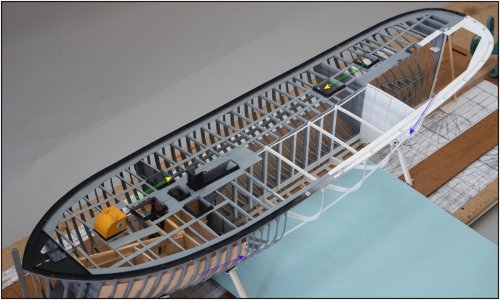
0459 Kimweger.jpg
Between the 2 blue arrows the 'white' port side bilge stringer with its hull shape curve.
I have chosen the angle of the photography in such a way that the 'grey' bilge stringer on the starboard side only shows a very small curve. It runs between the 2 yellow arrows. It has now the same little curve as the stringers on which the hatches are placed for access to the barrel holds. Those stringers only have the deck curve (sheer).

That shows once again that they thought a lot about their placement in the past. They have a double curve but still a kind of straight line to distribute the forces over the hull.
Regards, Peter
 
Last edited:
Back
Top