Thanks for this compliments, Shota. Much appreciated.Dear Peter, this is a impressive model build. The framing and detail is just incredible

Regards, Peter
 |
As a way to introduce our brass coins to the community, we will raffle off a free coin during the month of August. Follow link ABOVE for instructions for entering. |
 |
 |
The beloved Ships in Scale Magazine is back and charting a new course for 2026! Discover new skills, new techniques, and new inspirations in every issue. NOTE THAT OUR FIRST ISSUE WILL BE JAN/FEB 2026 |
 |
Thanks for this compliments, Shota. Much appreciated.Dear Peter, this is a impressive model build. The framing and detail is just incredible

When you break new ground, like you did with this one, I believe the following Einstein quote might apply. "If I had an hour to solve a problem, I would spend 55 minutes thinking about the problem and 5 minutes thinking about solutions." Again, brilliant work!Thanks, Johan. Indeed, besides the building there where many hours of thinking involved.
Regards, Peter
Took me 55 minutes to understand what he said...When you break new ground, like you did with this one, I believe the following Einstein quote might apply. "If I had an hour to solve a problem, I would spend 55 minutes thinking about the problem and 5 minutes thinking about solutions." Again, brilliant work!
Took me 55 minutes to understand what he said...
 .
.Thanks for pointing this quote from Einstein, Brad. Never heard of it, but it’s a nice one.When you break new ground, like you did with this one, I believe the following Einstein quote might apply. "If I had an hour to solve a problem, I would spend 55 minutes thinking about the problem and 5 minutes thinking about solutions." Again, brilliant work!

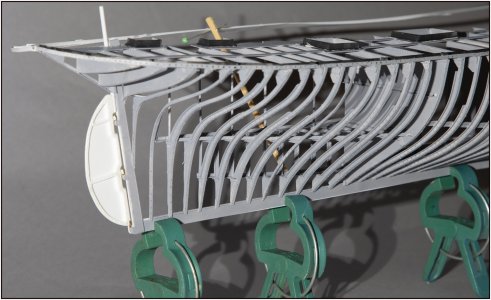
When you talk about ‘the next couple of years’, you are right ……Wow Peter nearly finished.
Yes, now they come more and more in view. Learned from the ‘imperfections’ on the SB side and avoid them on the BB side.Her fine lines are still impressive.

Thanks, Dean. I’ll try to nail your attention with the upcoming updates ……This is really unique and well done. I can’t wait to see the other side progress…with lots of details!
It’s actually quite riveting!

My thoughts exactlyIt‘ not a model, it‘s art. By some pictures I thought, that you show us renderd 3D images.
Just beautiful photographic
Thanks, Grant.My thoughts exactly
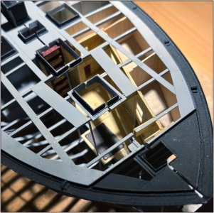
That is very nice work on the hinges. Ricci (Giampy) did something similar. I tried but failed.When transporting the model I have to make sure that the two halves are kept together.
View attachment 482858
Due to the weight or the movements they sometimes want to move apart. Till now I made a little clip, but that damages the paint.
I had already planned to make the structures over both half openings.
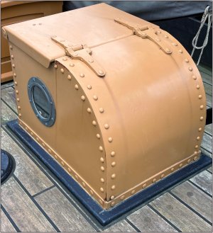
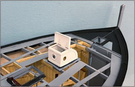
At the front is the sheet iron light cove above the stove in the forecastle:
View attachment 482859
The rectangular part, pointing to the rear, can be opened with a hinge to ventilate the space underneath.
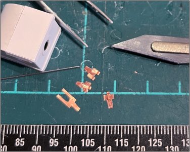
After the necessary tinkering it was time for the hinges:
View attachment 482860
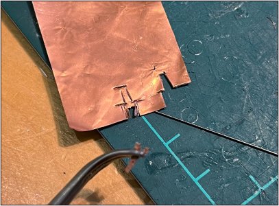
I still had 0.08 mm copper foil lying around and some 0.5 mm spring steel:
View attachment 482861
After some test cutting on different surfaces something workable emerged:
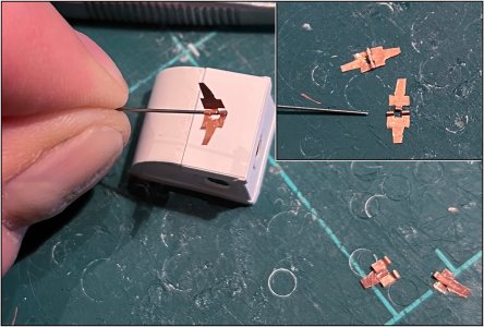
The 'fingers' were bent around the spring steel and the ends were secured with a tip of CA.
Then they are hinged:
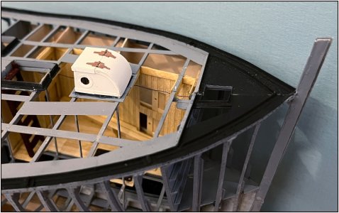
View attachment 482863
Everything in place:
View attachment 482864
And the forecastle can be ventilated:
View attachment 482865
Now apply all the rivets, spray, apply the 3 inner rings with glass ........
Regards, Peter
Thanks, Paul. I have not shown my 1st and 2nd attempt .......That is very nice work on the hinges. Ricci (Giampy) did something similar. I tried but failed.
Thanks, Daniel. 4 structures in the front and 1 on the aft will hold here firmly together.Excellent hinges. Small magnets, appropriately hidden (not too strong) come to mind for holding both halves together.
Thanks, Jim. The Dutch Riveter will go continue ........Nice miniature work, The Rivet Guy!! There are so many of those rivets, I am you can longer hear about, not just see.
You mean the forecastle itself, then you have to go 'a few pages' back for the look on the inside.Now, how this forecastle will be divided into halves?
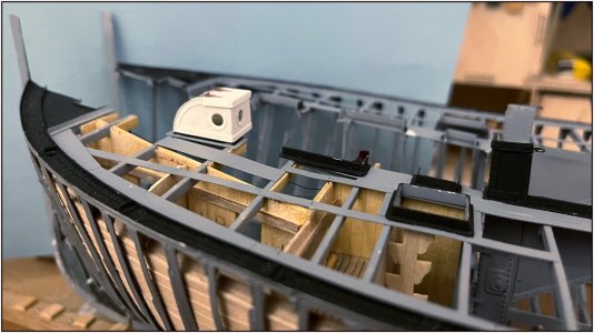
yep, this is exactly what I mean, thank you.Thanks, Jim. The Dutch Riveter will go continue ........
You mean the forecastle itself, then you have to go 'a few pages' back for the look on the inside.
Partly shown here. If you mean this structure? After the split during a show, the structure will be on the post side.
View attachment 482888
The little friction will hold here. I took the seam into account for the deck planks on this port side.
Regards, Peter
