HMS Enterprise 1774 POF 1:48.

At this scale I don’t have the skill with the blade to achieve that tapered notch.
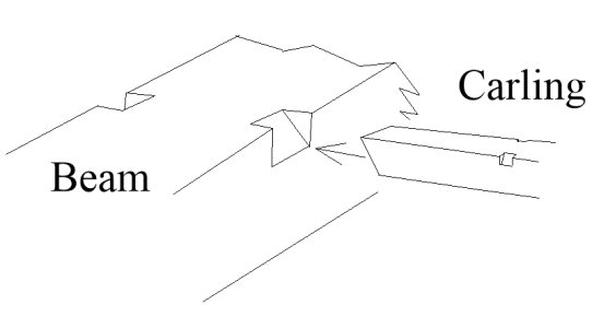
I bet you do! :) There are at least two well know modelers/ authors that just do a simple beveled cut and don't even bother putting a ledge on which the carling would rest in actual fill size construction. Two guide cuts with chisel or razor saw and one simple cut with the chisel or forget the side cuts and apply a few strokes with a narrow (1/8") pillar type Swiss file (which has no teeth on the edges) and done. The file is actually easier to control (for me at least) and I have
yet to cut myself with a file if it slips:)

1742929940282.png
 
Last edited:
Hi Grant. Just found your log. So sorry not seen it before now. I haven't looked through it yet as I needed to tell you l've found it!! Will begin as of now. We can compare the two kits as we go along, although it looks like l have a little catching up to do. Good luck with your build and l really hope you're enjoying yourself so far. Cheers mate
 
Hi Grant. A very impressive kit and you are making a great job of it! l´m so pleased you are enjoying this project. The kit looks like it differs quite a bit in design and construction but the ultimate result will obviously be a beautiful model of this great ship. My limited experience with CAF Models has been nothing but good and Tom is a very clever designer and very helpful if you have any issues. The very best of luck with this excellent project. I will be following along with great interest and if you don´t mind, we can compare notes and differences between our 2 kits.
Besrt wishes Keith
Good morning Keith. It will be fun to compare the two kits. So far I am enjoying this project and I agree the CAF kit is well thought out and designed. From what I have read the Dockyard is a brilliant kit (lovely structural accuracy) and I have not seen anyone else start this build so it will be cool to follow your progress . Cheers Grant
 
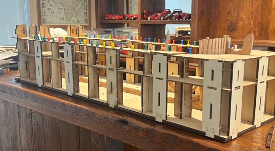
Good morning. My swear barrel has been emptied and my little challenge completed.

103461FE-64BB-4B83-9A71-B5CF68C30FB1.jpeg755D03D1-B105-4CD0-8943-2836CF804BE6.jpeg
Building this jig was a mission. Took about 12 hrs. The issue is the slots are all just too small and you have to sand each one open so the corresponding joint fits in….Sleep

Then the pictures on the instructions don’t give a sequence of which sections get placed in the base when. Get this wrong and some of the other “stantions” don’t fit in place later. So you have to remove what you did and redo after more head scratching . Removing these is a mission because I kept the joins tight so it all will be super strong when done. :mad:.

Anyway it is almost done, very sturdy and my center timbers fit in perfectly.:D:D.

I put pins all around the upper section so elastic bands may be attached to keep the frames tights against the upper slots.

Cheers Grant
 
Good morning. My swear barrel has been emptied and my little challenge completed.

View attachment 510479View attachment 510477
Building this jig was a mission. Took about 12 hrs. The issue is the slots are all just too small and you have to sand each one open so the corresponding joint fits in….Sleep

Then the pictures on the instructions don’t give a sequence of which sections get placed in the base when. Get this wrong and some of the other “stantions” don’t fit in place later. So you have to remove what you did and redo after more head scratching . Removing these is a mission because I kept the joins tight so it all will be super strong when done. :mad:.

Anyway it is almost done, very sturdy and my center timbers fit in perfectly.:D:D.

I put pins all around the upper section so elastic bands may be attached to keep the frames tights against the upper slots.

Cheers Grant
Lovely solid cradle there Grant. Now the real fun begins. Looking as if your Enterprise is settled sweetly in there.
Exciting.
 
Good morning. My swear barrel has been emptied and my little challenge completed.

View attachment 510479View attachment 510477
Building this jig was a mission. Took about 12 hrs. The issue is the slots are all just too small and you have to sand each one open so the corresponding joint fits in….Sleep

Then the pictures on the instructions don’t give a sequence of which sections get placed in the base when. Get this wrong and some of the other “stantions” don’t fit in place later. So you have to remove what you did and redo after more head scratching . Removing these is a mission because I kept the joins tight so it all will be super strong when done. :mad:.

Anyway it is almost done, very sturdy and my center timbers fit in perfectly.:D:D.

I put pins all around the upper section so elastic bands may be attached to keep the frames tights against the upper slots.

Cheers Grant
A solid base with a nicely fitted timber, Grant. And some Ferrari’s watching in the background.
Regards, Peter
 
Nice work on that jig Grant. The keel and hawse pieces look great sitting nicely in there. As we say in proper English, It's a big un aint it
 
Good morning. My swear barrel has been emptied and my little challenge completed.

View attachment 510479View attachment 510477
Building this jig was a mission. Took about 12 hrs. The issue is the slots are all just too small and you have to sand each one open so the corresponding joint fits in….Sleep

Then the pictures on the instructions don’t give a sequence of which sections get placed in the base when. Get this wrong and some of the other “stantions” don’t fit in place later. So you have to remove what you did and redo after more head scratching . Removing these is a mission because I kept the joins tight so it all will be super strong when done. :mad:.

Anyway it is almost done, very sturdy and my center timbers fit in perfectly.:D:D.

I put pins all around the upper section so elastic bands may be attached to keep the frames tights against the upper slots.

Cheers Grant
Hey Grant.
Your "shipyard"building JIG is awesome. I had the same issues with having to file all the slots. Have you glued in the parts ? I remember that I left the area of the stern unglued so I could take it apart when needed. Can you remove the keel structure from the jig at this time, or is it fixed ?
Here are some tips based on my experiences when I did this build. I am not as accomplished a builder as you are now, and this kit was way above my level back in 2020 when I started it, so please take that into account.
1) I remember having difficulty seating the frames on the keel slots...I didn't do a good enough job fitting each frame on to the keel-some sat deeper than others-If I had to do it all over again I would spend a LOT more time dry fitting each individual frame to the keel outside the jig, making sure that each frame sits at the same and correct height on the keel. It is a lot harder to do this inside the jig.
2) Having said that, the bow and hawse pieces as well as the stern need the jig for support. The bow is a solid compact tight structure (BTW, yours looks great ! )that doesn't need a lot of support to be b built-only after it is built..(it is built outside the jig anyway) However, it is the stern that gave me a lot of trouble. The stern needs a lot of support to be built correctly. My opinion is to build the stern inside the jig, but have some of the beams removable as you build it.
3) Remember that the location of the decks inside the hull is a real challenge with this build. Your swear barrels will be full. You may need extra barrels. The problem is to mark the location of the deck clamps. Again, a lot harder to do inside the jig. I would mark each frame with the location of deck clamp before it is glued on the keel. Some other kit makers have a system of matching holes in the jig where you slide a straight edge athwart the frames to locate the deck clamps. If I was doing this again, I would spend a lot of my time measuring this. I had to tear apart my deck clamps a couple of times, and my deck placement still didn't come out perfect.
Another problem related to this was that the plan showed a line, but was it corresponding to the level of the deck ? or is the line the top or the bottom of clamp? or the top of the deck above the frames with planking on ?. Super important to define that. Bryan had the same problems.
I will be really interested and watching how you solve this.
In reality, the CAF model is "harder" than the Dockyards because you need a lot of experience to figure out like deck placement etc., whereas the Dockyartds model seems to have all this stuff figured out for you.
Alex R
 
In reality, the CAF model is "harder" than the Dockyards because you need a lot of experience to figure out like deck placement etc., whereas the Dockyartds model seems to have all this stuff figured out for you.
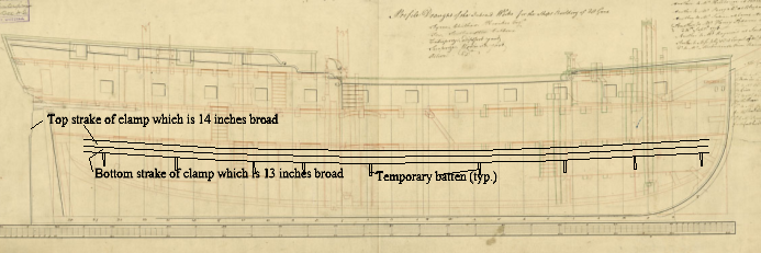
With the contemporary drawings and the contract getting exact locations it is not as difficult as some others we have all seen. Your method of marking out before hand definitely works if all the frames are perfectly placed, but I have had better luck marking out the line of the clamps after all the frames are erected and faired inboard and outboard. This may just be me, go with whatever is most comfortable. I mark the outside of the frames and attach temporary battens in between the frames for the clamp to rest on while being glued in place. It takes a bit of math, but given the deck heights it is pretty easy to do. From the contract for the deck heights

PLATFORM……….. Height between the upper Side of the plank or deal, on the platform to the Lower Side of the gun Deck Plank at the Middle of the deck fore Platform 6ft 2ins after Platform 5ft 11ins

LOWER DECK…. Beams to round 4 ins Plank thick 2 1/2 ins height from the plank of the lower deck to the upper side of the upper Deck Beams at the middle of the Beams, Afore 5ft 11ins & Abaft 5 ft 11 ins

UPPER DECK….. Height from the Upper Side of the Plank of the Upper Deck, to the Upper Side of the Quarter Deck Beams, at the Middle of the Beam, Afore
6 ft 2 ins, Abaft 6 ft 11 ins height of the Waste from the Upper Side of the Plank of the Deck at the Lowest Place 5 ft 2 ins height of the upper side of the lower port sill from the upper side of the plank of the upper deck 1 ft 9 ins, Ports deep 2 ft 3 ½ ins, fore & aft 2 ft 3 ½ ins Beams to round 7 ins, Plank thick 3 ins height from the upper side of the Plank of the upper Deck to the upper side of the fore Castle Beam at the middle of the Beam afore 5 ft 10 ins abaft 5 ft 10 ins.

Lacking a contract which is more often the case, the drawing can be used on its own.

The pic below may be more helpful. The dimensions of the lower deck clamp which consists of two strakes are from the contract. If the material in the kit is different, it is just a matter of adjusting the location of the temporary battens to suit the materials you have on hand.


Allan
1743274788234.png
 
Allan,
yes, thats the most accurate way. I didnt really do it correctly on my first (CAF) build of the Enterprize. The CAF kit in a sense is like a scratch build in this respect. Instructions were minimal, Allan was not watching and I was (am?) a beginner. Anyway, measure twice, cut once.
I hope that I am not so clueless in my upcoming Dockyards’ Enterprize. Im counting on all of you guys to advise and keep me out of trouble.
Alex R
 
Lovely solid cradle there Grant. Now the real fun begins. Looking as if your Enterprise is settled sweetly in there.
Exciting.
Hi Neil. Freak it took a while to make but it is certainly solid and is pulled up to ensure the verticals and any angles are correct and will not move. She did snuggle in rather nicely. Cheers Grant
 
Back
Top