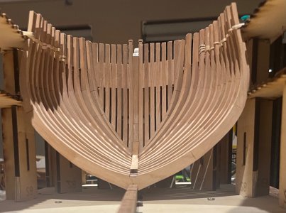
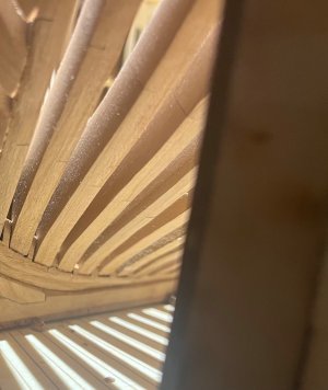
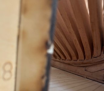
Thank Peter. Yep I am a Ferrari fan…. Not that my F1 team has been giving me much joy latelyA solid base with a nicely fitted timber, Grant. And some Ferrari’s watching in the background.
Regards, Peter

Good morning Maarten. So good to have you check in on my Enterprise. I am impressed with this CAF kit even though it is one of their early ones. I’m finding it challenging which is a good thing- lots of head scratching.Hi Grant,
Missed your start on this wonderfull model. Was one of the first fantastic kits coming from China.
Sure you will make something beautiful out of it.
Your building speed is impressive up to now.
True story. If I get it right will be a cool model……if I get it right being emphasisedShe's a big girl!
 .
.Thank you Daniel. The jig is brilliant, so solid and pulls everything up into perfect angles and lines. I fought with it while making it however it is worth all the effect.Thats a great looking and very sturdy jig, you're coming along at a nice pace Grant.
Thank you Keith. That it is. Will look cool tho when all done.Nice work on that jig Grant. The keel and hawse pieces look great sitting nicely in there. As we say in proper English, It's a big un aint it
Good morning Alex. Wow thank you for all this information and lessons learnt from experience. With the jig I did not use any glue. I kept the joint slots very tight (probably why I struggled so with it) and I’m impressed how it came out. I have not fully finished the aft section as I am working on the fore cant frames first. It is pretty much guess work right now and I’m sure some issues are coming my way. Thank you again for this post as it has made me aware of upcoming challenges. I will take your advice on these pointers.Hey Grant.
Your "shipyard"building JIG is awesome. I had the same issues with having to file all the slots. Have you glued in the parts ? I remember that I left the area of the stern unglued so I could take it apart when needed. Can you remove the keel structure from the jig at this time, or is it fixed ?
Here are some tips based on my experiences when I did this build. I am not as accomplished a builder as you are now, and this kit was way above my level back in 2020 when I started it, so please take that into account.
1) I remember having difficulty seating the frames on the keel slots...I didn't do a good enough job fitting each frame on to the keel-some sat deeper than others-If I had to do it all over again I would spend a LOT more time dry fitting each individual frame to the keel outside the jig, making sure that each frame sits at the same and correct height on the keel. It is a lot harder to do this inside the jig.
2) Having said that, the bow and hawse pieces as well as the stern need the jig for support. The bow is a solid compact tight structure (BTW, yours looks great ! )that doesn't need a lot of support to be b built-only after it is built..(it is built outside the jig anyway) However, it is the stern that gave me a lot of trouble. The stern needs a lot of support to be built correctly. My opinion is to build the stern inside the jig, but have some of the beams removable as you build it.
3) Remember that the location of the decks inside the hull is a real challenge with this build. Your swear barrels will be full. You may need extra barrels. The problem is to mark the location of the deck clamps. Again, a lot harder to do inside the jig. I would mark each frame with the location of deck clamp before it is glued on the keel. Some other kit makers have a system of matching holes in the jig where you slide a straight edge athwart the frames to locate the deck clamps. If I was doing this again, I would spend a lot of my time measuring this. I had to tear apart my deck clamps a couple of times, and my deck placement still didn't come out perfect.
Another problem related to this was that the plan showed a line, but was it corresponding to the level of the deck ? or is the line the top or the bottom of clamp? or the top of the deck above the frames with planking on ?. Super important to define that. Bryan had the same problems.
I will be really interested and watching how you solve this.
In reality, the CAF model is "harder" than the Dockyards because you need a lot of experience to figure out like deck placement etc., whereas the Dockyartds model seems to have all this stuff figured out for you.
Alex R
Maarten told me this was an early CAf kit and I think the difficulty comes from the design and instructions by CAF. If I understood more of the internal structures of these ships I may decipher CAFs interpretation better and not have to guess quite so much.
Cheers Grant
Good afternoon Allan. Very clever method for marking the deck height. I will probably give this a go, although I will need to do some maths first…..hmmm I’m not the best at mathsWith the contemporary drawings and the contract getting exact locations it is not as difficult as some others we have all seen. Your method of marking out before hand definitely works if all the frames are perfectly placed, but I have had better luck marking out the line of the clamps after all the frames are erected and faired inboard and outboard. This may just be me, go with whatever is most comfortable. I mark the outside of the frames and attach temporary battens in between the frames for the clamp to rest on while being glued in place. It takes a bit of math, but given the deck heights it is pretty easy to do. From the contract for the deck heights
PLATFORM……….. Height between the upper Side of the plank or deal, on the platform to the Lower Side of the gun Deck Plank at the Middle of the deck fore Platform 6ft 2ins after Platform 5ft 11ins
LOWER DECK…. Beams to round 4 ins Plank thick 2 1/2 ins height from the plank of the lower deck to the upper side of the upper Deck Beams at the middle of the Beams, Afore 5ft 11ins & Abaft 5 ft 11 ins
UPPER DECK….. Height from the Upper Side of the Plank of the Upper Deck, to the Upper Side of the Quarter Deck Beams, at the Middle of the Beam, Afore
6 ft 2 ins, Abaft 6 ft 11 ins height of the Waste from the Upper Side of the Plank of the Deck at the Lowest Place 5 ft 2 ins height of the upper side of the lower port sill from the upper side of the plank of the upper deck 1 ft 9 ins, Ports deep 2 ft 3 ½ ins, fore & aft 2 ft 3 ½ ins Beams to round 7 ins, Plank thick 3 ins height from the upper side of the Plank of the upper Deck to the upper side of the fore Castle Beam at the middle of the Beam afore 5 ft 10 ins abaft 5 ft 10 ins.
Lacking a contract which is more often the case, the drawing can be used on its own.
The pic below may be more helpful. The dimensions of the lower deck clamp which consists of two strakes are from the contract. If the material in the kit is different, it is just a matter of adjusting the location of the temporary battens to suit the materials you have on hand.
Allan
View attachment 510587
 . Your post, as always Allan, is much appreciated.
Cheers Grant


