
• Ships of Scale has incorportated an extra level of security when you log In. Please follow on-screen prompts to acknowledge that you are not a robot via a "Check Box" or a "Pictorial Check Box Puzzle". This is needed due to higher level of AI Activity Security.
  • SUBSCRIBE TO SHIPS IN SCALE TODAY!

    The beloved Ships in Scale Magazine is back and charting a new course for 2026!
    Discover new skills, new techniques, and new inspirations in every issue.

    NOTE THAT OUR NEXT ISSUE WILL BE July/August 2026
  • Win a Free Custom Engraved Brass Coin!!!
    As a way to introduce our brass coins to the community, we will raffle off a free coin during the month of August. Follow link ABOVE for instructions for entering.

The Black Swan by OcCre 1:75: Build Log

The gunport covers were primed, painted black and installed into the gunports. The cannons and "false" half cannons were prepared. I have to complement Occre on the casting of the cannons and really all their castings. They are exceptionally crisp and free of flash. Nice work on their part! The cannons were washed in dish soap and hot water to get rid of any releasing agent, rinsed and dried. I set them up on a piece of foam board to hold them and primed them and painted them black.
Great tip to have into account when working the gunport of the Golden Hind I´m building. Didn't think about cleaning and removal of any releasing agent. Always learning !!
 
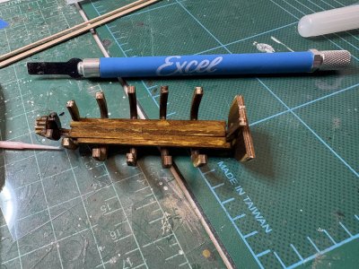
After the floor lumbers were attached to the launch the frame and floor were stained with the walnut stain.

IMG_0533.jpeg

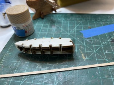
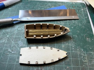
The laser cut building platform that provides support when planking the launch was glued into place and the frames faired in preparation for the planking.

IMG_0535.jpeg

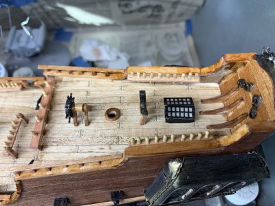
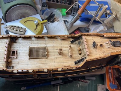
While waiting for things to dry the small skylight that provides light for the gallery was constructed and painted. It was glued to the appropriate location on the poop deck.

IMG_0534.jpeg
 
Last edited:
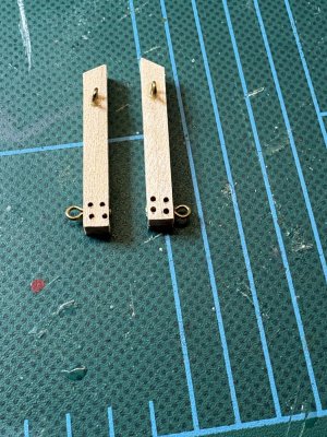
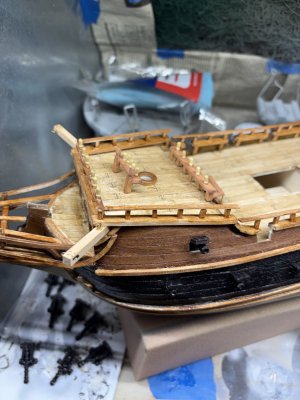
Two catheads were constructed using 4x4mm strip.

IMG_0544.jpeg

I wanted to make sure they were solidly attached to the hull so 5 minute epoxy was used to secure them.

IMG_0545.jpeg

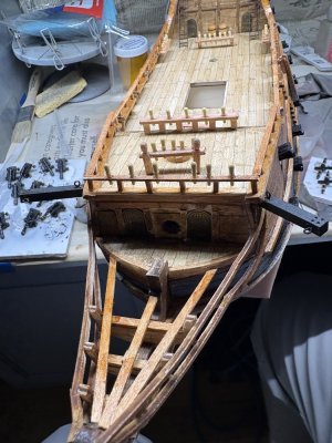
They were then painted black.

IMG_0547.jpeg

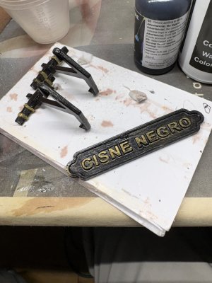
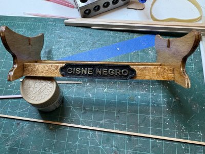
While I was waiting for the epoxy to set the anchors were assembled and painted as well as the plaque with the ships name that goes on the cradle that holds the ship.

IMG_0546.jpeg
 
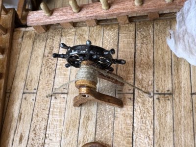
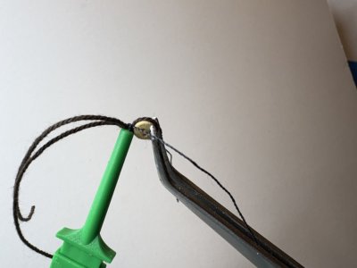
To simulate the steering cable. 0.15mm line was wrapped around the drum on the ships wheel. The instructions would have you set two eyebolts on the deck and tie the line to them. I did not like the look of this. Instead I drilled 2 0.8mm holes when the eyebolts would be attached and glued one end of the line into one of the holes and let it dry. I then wrapped the line around the drum. After several turns I glued the line to the drum suing a dab of glue on the bottom of the drum to conceal it. The free end of the line was held in tension using a clamp until the glue set. After that, the free end was fed into the second hole and held with tweezers in tension until the glue set.

IMG_0550.jpeg
 
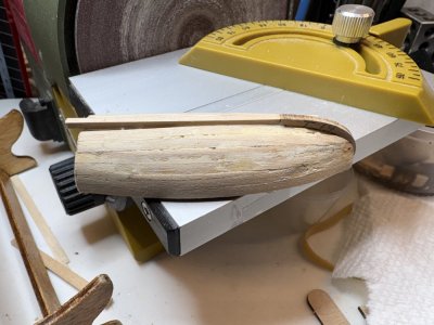
The launches planking was completed and the hull was sanded and some wood filler used. The keel was attached. The cured keel piece that goes in the from is mislabeled as T-15. The photographic identifies it as S-14.

IMG_0558.jpeg

Th support base was cut out from the bottom.

IMG_0556.jpeg
 
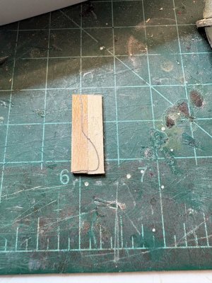
In order to jazz up the launch a little I decided to make a rudder for it. I didn't think a rudderless launch would do. I glued together 2 pieces of 4x4mm strip and traced a rudder design onto it.
IMG_0563.jpeg

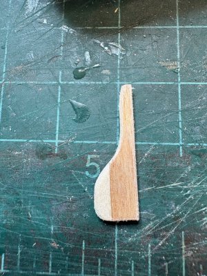
I cut the design out and using my nail drill I rounded the edges.

IMG_0565.jpeg

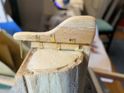
Using some metallic tape, "hinges" were fashioned on the hull and the rudder and it was glued into place with CA. A tiller was made from some wire.

IMG_0568.jpeg


I will probably be painting the hull and rudder, but the hinges will be evident under the paint.
 
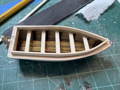
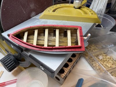
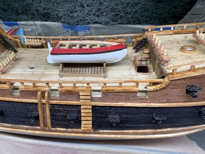
Using 1x3mm strip some thwarts and a railing was made for the launch and glued into place with some PVA. The railing was bent using some heat and soaking the wood.

IMG_0571.jpeg

After allowing the PVA to dry the launch was sanded again with some 400 grit sanding block and coated with 2 coats of sanding sealer.
 
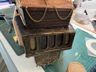
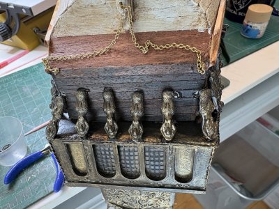
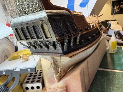
This should have been done before, but there are 12 casted figurines that are to be place below the captains cabin (gallery?) that I suppose were to help support it. These really should be put on before all the deck furniture is added. To do it the ship was placed upside down (I use a soft foam cradle when building this ship).

IMG_0572.jpeg

To make sure the figurines were securely held in place 5 minute epoxy was used instead of CA. The figurines were held in place until the epoxy was tacky. I used a mall dental applicator to remove excess epoxy.

IMG_0573.jpeg


The epoxy was allowed to dry for several hours before I moved the ship. It looks much better right side up!

IMG_0575.jpeg
 
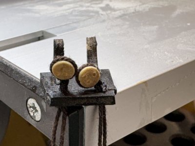
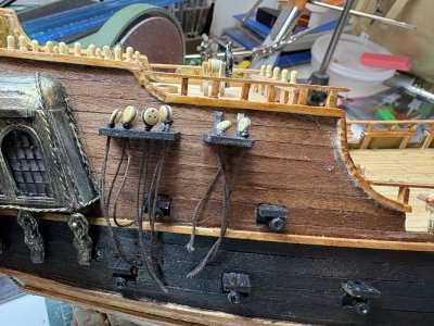
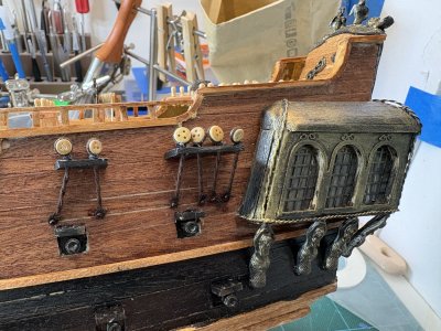
The channels are next. They use some line instead of chain plates. Im not a big fan but it is what it is. I decided to attach the deadeyes to the channels before they are installed. I think it may be easier. There are two sizes of deadeyes, but the pictures are pretty explicit about what goes where. Each deadeye was checked and drilled to make sure the channels for the lanyards were clear. The smaller deadeyes especially had channels that were blocked. Better to make sure they are clear now then when attached to the ship. The deadeyes were seized to the lines. I use these small electrical test clips as small clamps to hold the lines. I find them easier to use than alligator clips.

IMG_0581.jpeg

The deadeyes were rotated to the correct position. I had to enlarge the holes on the channels to allow the lines to pass. I used a needle threader to help with that.

IMG_0577.jpeg
 
Last edited:
The channels were attached to the hull with CA. A small pin was inserted into the back of the channel and a hole made into the hull to help with a more secure attachment. There is not a lot of information provided to determine where the channels should go. The best I found was pictures showing the arrangement of different size deadeyes on the channels. The picture showed where the channels were located relative to the deck and guns.

IMG_0583.jpeg

When the channels were firmly attached to the hull the lines representing the chain plates were twisted around each other and nails set 18mm bellow the channels. The line was twisted around the nails and they were set with CA. The nails were blackened by using a sharpie.

IMG_0585.jpeg
 
Back
Top