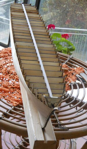
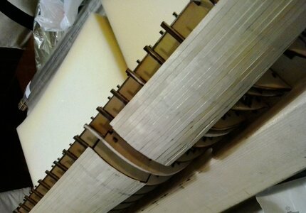
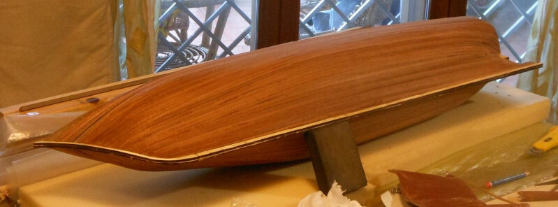
1/60 scale RC model of a schooner, loosely based on a gunboat steamship from the second half of the 19th century.

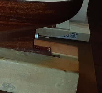
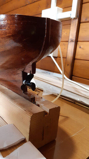
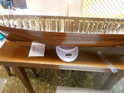
I would call it a waterline marker jig. If you refer to those apparently foam parts, assuming you use them to get the waterline marker at the right height, I would refer to it as spacer.


Esattamente questo: waterline marker jig.
Ora so come si chiama, grazie molte.

Exactly this: waterline marker jig.

Now what's his name, thank you very much.
 
A very impressive hull - very good work Thumbsup
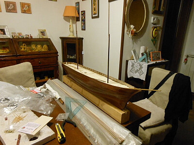
Interesting also is the way you mark by a vertical pencil the hull form ?
Is it to compare and check both sides of the hull form afterwards - or why are you doing this ?
 
A very impressive hull - very good work Thumbsup
Interesting also is the way you mark by a vertical pencil the hull form ?
Is it to compare and check both sides of the hull form afterwards - or why are you doing this ?
Salve Uwek. Grazie mille.

Sì, hai capito bene.
Talvolta mi viene il dubbio che le mie traduzioni non siano molto comprensibili.

Lo scopo è segnare tutte le linee d'acqua sullo scafo e contemporaneamente riportarle su un foglio in modo da analizzarle, confrontarle e segnare appunti sullo scafo (esempio: riempire di… abbassare di …).
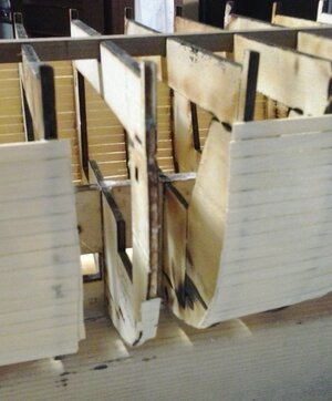
Se il taglio delle cornici fosse andato bene non ce ne sarebbe stato bisogno. Purtoppo l'eccessiva bruciatura ha tolto troppo legno dai bordi delle cornici. Anche nei punti dove si incastravano con la chiglia.
In questo modo le ordinate erano lente, "ballavano" qualcuna troppo a sinistra e qualcuna troppo a destra.
Il regolo (quadrello di legno) sopra a tutto non ha risolto completamente l'allineamento.
Dopo il controllo con il "waterline marker" ho dovuto tagliare alcune parti di scafo, pareggiare le frames e rifare il fasciame nei punti dove c'erano errori. In pratica ho messo delle toppe.
Non ho mai usato, però, lo stucco. Non mi piace.

Hello Uwek. Thank you very much.

Yes, you understood correctly.
Sometimes I doubt that my translations are not very understandable.

The aim is to mark all the water lines on the hull and at the same time record them on a sheet of paper in order to analyze them, compare them and make notes on the hull (example: fill with... lower with...).

If the cutting of the frames had gone well there would have been no need.
Unfortunately, the excessive burning took away too much wood from the edges of the frames.
Even in the places where they stuck with the keel.
In this way the frames were slow, some "danced" too much to the left and some too much to the right.
Above all, the ruler (wooden square) did not completely resolve the alignment.
After checking with the "waterline marker" I had to cut some parts of the hull, level the frames and redo the planking in the places where there were errors. Basically I put some patches.
However, I have never used stucco. I don't like.


20141013.jpg

dscn2010.jpg

20141010.jpg

20141012.jpg

20141011.jpg
 
Last edited:
Salve a tutti.

Dopo il primo fasciame ho effettuato le dovute correzioni.
Dopodichè, ho proceduto alla posa del secondo fasciame con listelli di mogano, spesso 1 mm.
Non ho usato chiodini o altri sistemi di serraggio. Ho usato colla tipo mastice. Non conosco il termine inglese per questo tipo di colla.
Questo tipo di colla, molto comune ed economica, va messa su entrambe le superfici da incollare, si aspetta circa 20 o 30 minuti e, solo allora, si uniscono premendole forte fra loro.

Attenzione:
Se ci fate caso, nelle prime foto, la chiglia in legno era ancora integra.

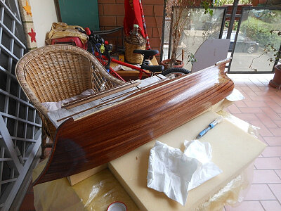
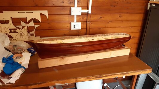
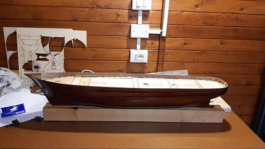
Nelle foto allegate, potete vedere il modello appena verniciato.

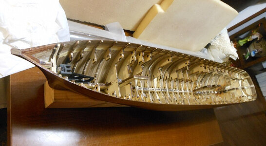
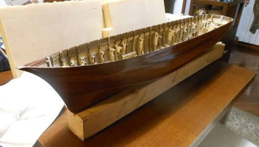
Le ordinate sono state ridotte a delle costole. Infatti, è stata tolta tutta la parte interna, che serviva solo per fornire robustezza, mentre costruivo lo scafo, mettendo il fasciame.

Ho ottenuto uno scafo molto leggero, leggerissimo. Ma in questo modo sarebbe stato troppo fragile. Ecco perchè, in alcune foto potete notare i listelli di noce messi in verticale. Un fasciame verticale certamente insolito.
Quello che ha dato robustezza assoluta allo scafo è stata la resina, che ho spalmato al suo interno. In questo modo, lo scafo è passato dagli 804 grammi ai 939 grammi.

I ponti non erano ancora incollati, ma appoggiati solo per prova.
Li incollai solo dopo aver completato tutto l'allestimento elettrico.

Attenzione alla foto del modello verniciato, vedete che parte della chiglia è stata tolta? Già avrete capito il motivo.

Hello everyone.

After the first planking I made the necessary corrections.
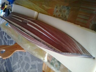
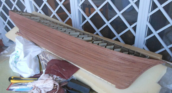
Afterwards, I proceeded to lay the second planking with mahogany strips, 1 mm thick.

I didn't use nails or other tightening systems. I used putty type glue. I don't know the English term for this type of glue.
This type of glue, very common and economical, must be put on both surfaces to be glued, wait about 20 or 30 minutes and, only then, join by pressing them hard together.

Attention: If you notice, in the first photos, the wooden keel was still intact.

In the attached photos, you can see the freshly painted model.
The frames have been reduced to ribs. In fact, the entire internal part was removed, which only served to provide strength, while I built the hull, placing the planking.

I got a very light hull, very light.
But that way it would have been too fragile.
This is why, in some photos you can see the walnut strips placed vertically. A vertical planking that is certainly unusual.
What gave the hull absolute strength was the resin, which I spread inside. In this way, the hull went from 804 grams to 939 grams.

The bridges were not yet glued, but only supported for testing.
I glued them only after completing all the electrical setup.

Pay attention to the photo of the painted model, do you see that part of the keel has been removed? You will already understand why.


41u3uNgrIjL._SX342_SY445_QL70_ML2_.jpg

20150412.jpg

1n.jpg

n.jpg

3n.jpg

5n.jpg

dscn4217.jpg

4n.jpg

7n.jpg

20200501_122932 bis.jpg

9n.jpg
 
One thing's certain; all your planning and preparations did pay off. You build yourself a beautiful hull. From my perspective imperfections are not discernable.
Grazie tante RDN1954. Troppo buono. Sono parole molto belle.

Effettivamente, alla fine sono riuscito a risolvere gli errori.
Le mie precisazioni soprattutto per racconatre la storia di questo progetto.
Alcune indicazioni erano anche per chi voleva riprodurre lo stesso progetto. Avevo timore che potesse incorrere nei miei stessi contrattempi, perdendo molto tempo.

Thanks so much RDN1954. Too good. They are very beautiful words.

Actually, I finally managed to fix the errors.
My clarifications above all to tell the story of this project.
Some indications were also for those who wanted to reproduce the same project. I was afraid that he might run into the same setbacks as me, wasting a lot of time.
 
I already wrote this on my Bluenose POF blog, but currently being close to completion of the BN, I am contemplating which model to build next. There are some options, one including using a saw, where I want to cut the hull in half on its waterline and add an interior, a second one that of a Dutch tug from around 1920/1930 and now you presented me with a third option. Luckily I stil,have time to decide...
 
Buona giornata a tutti.

Proseguo con la descrizione delle fasi di costruzione per arrivare ai problemi odierni.
Sto riassumendo molto e spero di non annoiarvi, tuttavia, se qualcuno volesse maggiori dettagli sarò molto contento di fornirglieli.

Dunque, ho calcolato che il modello aveva un dislocamento di circa 5 kg per mantenere la linea di galleggiamento disegnata. Con maggior peso avrei avuto un bordo libero troppo esiguo.
In realtà il dato calcolato era il volume immerso, poco più di 5 dm3, quindi l'equivalente di circa 5 litri (o cinque kg di acqua dolce).

Tuttavia era necessario verificare questo dato con una prova.
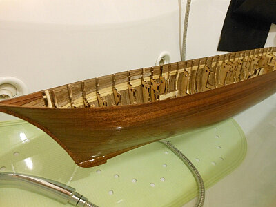
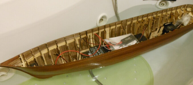
Perciò ho messo il modello nella vasca da bagno. In questo modo ho testato anche l'impermeabilizzazione dello scafo. In effetti non avevo dubbi, perchè le vernice esterna e la resina interna garantivano l'impermeabilizzazione.

Per le prove mi facevo, e mi faccio ancora oggi, aiutare da mio figlio. In questo modo capisce meglio molti concetti di fisica. Ad esempio, a scuola non ha avuto alcuna difficoltà con il principio di Archimede, anzì ha primeggiato.
Inoltre, il committente dei lavori è lui e la nave sarà sua non appena terminata. Ha tutto l'interesse a controllare che vengano eseguiti bene, ahahahahahah.

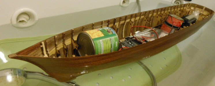
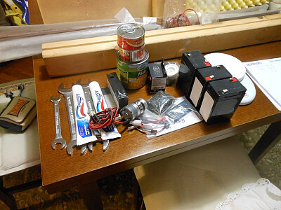
La prova è stata molto semplice: abbiamo inserito man mano vari oggetti fino ad arrivare alla linea di galleggiamento prefissata. Dopodichè abbiamo pesato questi oggetti ed è risultato effettivamente un peso totale di poco più di 5 kg in acqua dolce.


Have a nice day everyone.

I continue with the description of the construction phases to get to today's problems.
I am summarizing a lot and hope not to bore you, however, if anyone wants more details I will be very happy to provide them.

So, I calculated that the model had a displacement of about 5 kg to maintain the drawn waterline.
With more weight I would have had too little freeboard.
In reality the calculated data was the immersed volume, just over 5 dm3, therefore the equivalent of approximately 5 liters (or five kg of fresh water).

However, it was necessary to verify this data with a test.
So I put the model in the bathtub.
In this way I also tested the waterproofing of the hull.
In fact I had no doubts, because the external paint and the internal resin guaranteed waterproofing.

For the tests I had, and still do today, help from my son. In this way he better understands many physics concepts. For example, at school he had no difficulty with Archimedes' principle, in fact he excelled.
Furthermore, he is the client of the works and the ship will belong to him as soon as it is finished. He has every interest in checking that they are done well, ahahahahahah.

The test was very simple: we gradually inserted various objects until we reached the pre-established water line. We then weighed these objects and it actually turned out to have a total weight of just over 5 kg in fresh water.


1n.jpg

2n.jpg

3n.jpg

4n.jpg
 
Your comments are correct.
Consider, however, that many choices were made when my knowledge was very limited. During the realization phase I gradually acquired a lot of information from books and on the internet (texts, images and videos).
Today I am satisfied only with some technical choices that I have adopted, even if unusual, but many choices are to be avoided, today I would not do them again.
As for the "bending pliers", I didn't need it as long as the hulls of the models had a flat "transom". In this case, as you rightly say: "the curvatures seem to be rather benign".
In this model the poop, however, is round and the curvatures are very accentuated, you even have to make a circle on the strips closest to the bridge.
In order not to break them, many methods can be used: candle, steam, boiling water, etc. etc. All very laborious and long methods in my opinion.
The pliers folding strips are brilliant as simple, bends the strip thanks to the notches it makes on the wood, without breaking it.
The thicker the notches that are made, the more the curvature of the wooden strip is accentuated. The notches are unsightly (ugly to look at), but there is no problem, because they always happen in the concave part and therefore are not visible.
It's amazing how late I discovered this tool that everyone knew.

Your observations are correct.

Consider, however, that many choices were made when my knowledge was very limited.
During the creation phase I gradually acquired a lot of information from books and on the internet (texts, images and videos).
Today I am only satisfied with some of the technical choices I have adopted, even if they are unusual, but many choices are to be avoided and I wouldn't do them again today.

As for the bending pliers, I didn't need them as long as the model hulls had a flat transom.
In this case, as you rightly say: "the curvatures appear to be rather benign".
In this model, however, the poop is round and the curvatures are very accentuated, you even have to make a circle on the slats closest to the bridge.
To avoid breaking them, many methods can be used: candle, steam, boiling water, etc. etc. All very laborious and time-consuming methods in my opinion.
The strip bending pliers are ingenious yet simple, they bend the strip thanks to the notches they make on the wood, without breaking it.
The denser the notches are made, the more accentuated the curvature of the wooden sThe notches are unsightly (unsightly), but there is no problem, because they always occur in the concave part and therefore are not visible. It's amazing how late I discovered this tool that everyone knew about.
lectricA soldering ironectric bender. Once again, but
 
Your comments are correct.
Consider, however, that many choices were made when my knowledge was very limited. During the realization phase I gradually acquired a lot of information from books and on the internet (texts, images and videos).
Today I am satisfied only with some technical choices that I have adopted, even if unusual, but many choices are to be avoided, today I would not do them again.
As for the "bending pliers", I didn't need it as long as the hulls of the models had a flat "transom". In this case, as you rightly say: "the curvatures seem to be rather benign".
In this model the poop, however, is round and the curvatures are very accentuated, you even have to make a circle on the strips closest to the bridge.
In order not to break them, many methods can be used: candle, steam, boiling water, etc. etc. All very laborious and long methods in my opinion.
The pliers folding strips are brilliant as simple, bends the strip thanks to the notches it makes on the wood, without breaking it.
The thicker the notches that are made, the more the curvature of the wooden strip is accentuated. The notches are unsightly (ugly to look at), but there is no problem, because they always happen in the concave part and therefore are not visible.
It's amazing how late I discovered this tool that everyone knew.

Your observations are correct.

Consider, however, that many choices were made when my knowledge was very limited.
During the creation phase I gradually acquired a lot of information from books and on the internet (texts, images and videos).
Today I am only satisfied with some of the technical choices I have adopted, even if they are unusual, but many choices are to be avoided and I wouldn't do them again today.

As for the bending pliers, I didn't need them as long as the model hulls had a flat transom.
In this case, as you rightly say: "the curvatures appear to be rather benign".
In this model, however, the poop is round and the curvatures are very accentuated, you even have to make a circle on the slats closest to the bridge.
To avoid breaking them, many methods can be used: candle, steam, boiling water, etc. etc. All very laborious and time-consuming methods in my opinion.
The strip bending pliers are ingenious yet simple, they bend the strip thanks to the notches they make on the wood, without breaking it.
The denser the notches are made, the more accentuated the curvature of the wooden strip is.
The notches are unsightly (unsightly), but there is no problem, because they always occur in the concave part and therefore are not visible. It's amazing how late I discovered this tool that everyone knew about.


View attachment 396685
 
I have been trying without success to use the "respoor"
Ciao Peter, buonasera.
Scusami non so che cosa sia il "respoor".

Se intendi il "Reply" non ti preoccupare, anch'io all'inizio ho fatto un pò di casino.

Hi Peter, good evening.

Sorry, I don't know what "respoor" is.


If you mean the "Reply" don't worry, I made a bit of a mess at the beginning too.
 
Buona giornata a tutti.

Proseguo con la descrizione delle fasi di costruzione per arrivare ai problemi odierni.
Sto riassumendo molto e spero di non annoiarvi, tuttavia, se qualcuno volesse maggiori dettagli sarò molto contento di fornirglieli.

Dunque, ho calcolato che il modello aveva un dislocamento di circa 5 kg per mantenere la linea di galleggiamento disegnata. Con maggior peso avrei avuto un bordo libero troppo esiguo.
In realtà il dato calcolato era il volume immerso, poco più di 5 dm3, quindi l'equivalente di circa 5 litri (o cinque kg di acqua dolce).

Tuttavia era necessario verificare questo dato con una prova.
Perciò ho messo il modello nella vasca da bagno. In questo modo ho testato anche l'impermeabilizzazione dello scafo. In effetti non avevo dubbi, perchè le vernice esterna e la resina interna garantivano l'impermeabilizzazione.

Per le prove mi facevo, e mi faccio ancora oggi, aiutare da mio figlio. In questo modo capisce meglio molti concetti di fisica. Ad esempio, a scuola non ha avuto alcuna difficoltà con il principio di Archimede, anzì ha primeggiato.
Inoltre, il committente dei lavori è lui e la nave sarà sua non appena terminata. Ha tutto l'interesse a controllare che vengano eseguiti bene, ahahahahahah.

La prova è stata molto semplice: abbiamo inserito man mano vari oggetti fino ad arrivare alla linea di galleggiamento prefissata. Dopodichè abbiamo pesato questi oggetti ed è risultato effettivamente un peso totale di poco più di 5 kg in acqua dolce.


Have a nice day everyone.

I continue with the description of the construction phases to get to today's problems.
I am summarizing a lot and hope not to bore you, however, if anyone wants more details I will be very happy to provide them.

So, I calculated that the model had a displacement of about 5 kg to maintain the drawn waterline.
With more weight I would have had too little freeboard.
In reality the calculated data was the immersed volume, just over 5 dm3, therefore the equivalent of approximately 5 liters (or five kg of fresh water).

However, it was necessary to verify this data with a test.
So I put the model in the bathtub.
In this way I also tested the waterproofing of the hull.
In fact I had no doubts, because the external paint and the internal resin guaranteed waterproofing.

For the tests I had, and still do today, help from my son. In this way he better understands many physics concepts. For example, at school he had no difficulty with Archimedes' principle, in fact he excelled.
Furthermore, he is the client of the works and the ship will belong to him as soon as it is finished. He has every interest in checking that they are done well, ahahahahahah.

The test was very simple: we gradually inserted various objects until we reached the pre-established water line. We then weighed these objects and it actually turned out to have a total weight of just over 5 kg in fresh water.


View attachment 397344

View attachment 397345

View attachment 397346

View attachment 397347
Probably a very silly question, but wouldn't you need a ballast keel to keep her on even keel when under sail?
 
Alessandro, bellissimo lavoro di progettazione ed esecuzione. Congratulazione.
Qual è la scala del modello ?
Ottimo italiano, ma dal messaggio e dal nome credo che tu sia proprio italiano.

Ti ringrazio delle belle parole di apprezzamento.

La scala è 1:60.


Excellent Italian, but from the message and the name I think you are really Italian.


Thank you for the kind words of appreciation.


The scale is 1:60.
 
Probably a very silly question, but wouldn't you need a ballast keel to keep her on even keel when under sail?


Ciao Johan (RDN1954).

No, non è una domanda sciocca. Anzi molto arguta e intelligente, come tutti i messaggi che hai fatto finora.

La zavorra ci sarà, la farò vedere in successive foto, ma non voglio creare dei messaggi giganteschi con troppe foto e quindi illeggibili.

Te lo anticipo un pò.
Considera che, anche senza zavorra, il modello finito era ben bilanciato e aveva una buona spinta raddrizzante laterale.
Buona, ma non fortissima, quindi con venti forti al traverso forse sarebbe stato in difficoltà.
Ero riuscito ad ottenere questo risultato con la disposizione dei pesi utili (non zavorre).
Con l'applicazione della zavorra ho ottenuto una spinta raddrizzante laterale veramente efficace.

Indovina, se vuoi, dove e come ho messo la zavorra.


Hi (Johan) RDN1954.


No, it's not a silly question. Indeed very witty and intelligent, like all the messages you have made so far.


The ballast will be there, I will show it in subsequent photos, but I don't want to create gigantic messages with too many photos and therefore unreadable.


I'll give you a heads up a bit.

Consider that, even without ballast, the finished model was well balanced and had good lateral righting thrust.

Good, but not very strong, so with strong crosswinds perhaps he would have been in difficulty.

I managed to achieve this result with the arrangement of useful weights (not ballasts).

With the application of the ballast I obtained a truly effective lateral straightening thrust.


Guess, if you want, where and how I put the ballast.
 
Last edited:
Salve a tutti i modellisti!
Continuo ad illustrare le fasi di montaggio.
Ho proceduto da autodidatta ma ho seguito molti consigli utili.
In alcuni casi, la soluzione che ho adotatto, per uno specifico problema, non era forse la migliore.
Non abbiate timore di commentare negativamente alcune scelte.
Se, però, qualche scelta tecnica, un pò fuori standard, potrà essere utile agli altri sarò veramente contento.

Dunque, dopo aver aperto gli spazi interni dello scafo, bisognava introdurre con criterio: motore, servomeccanismi, ricevente, variatore di tensione e batterie.
Già nel progetto, la loro collocazione era più in basso possibile.

Tuttavia prima di questo ho pensato alla trasmissione motore - elica.
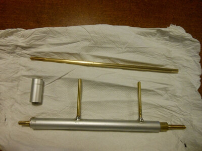
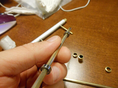
Ci sono in commercio astucci per assi dell'elica già completi in acciaio, ma io ho preferito farlo da solo perchè non erano della lunghezza giusta.
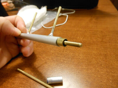
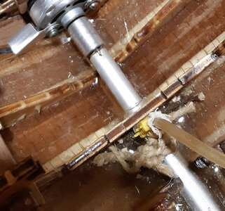
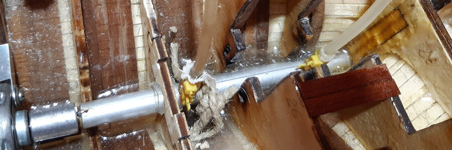
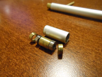
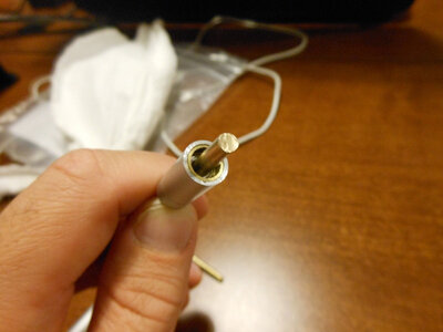
In queste immagini allegate, potete vedere alcune fasi di assemblaggio.
L'asse è un tondino pieno di ottone che ho filettato io. Il suo diametro è 4 mm.
I microcuscinetti hanno un diametro interno di 4 mm e un diametro esterno di 8 mm.
L'astuccio esterno è costituito da un cilindro di alluminio del diametro interno di 8 mm e di diametro esterno di 10 mm.
I distanziatori interni, che separano i cuscinetti, sono tubi di ottone del diametro esterno di 8 mm.
Il tubo di alluminio ha dei tubicini per l'inserimento dall'esterno del grasso.
Tutto pieno di grasso siliconico, è molto difficile che l'acqua arrivi ai cuscinetti, tanto meno all'interno della stiva.

Ad differenza di quasi tutti gli altri elementi, il tubo di trasmissione non è amovibile, esso è saldamente bloccato sul fondo dello scafo, immerso nella resina.
E' perfettamente in asse con il motore ed è ad esso collegato con un giunto normale (non un giunto cardanico). Inoltre, è parallelo al deck e alla chiglia. In questo modo tutta la spinta è utile e non ci sono componenti verticali che vanno sprecate, come nel caso di un asse leggermente obbliquo.


Hello all modelers!

I continue to illustrate the assembly phases.
I proceeded as a self-taught but I followed many useful tips.
In some cases, the solution I adopted for a specific problem was perhaps not the best.
Don't be afraid to comment negatively on some choices.
If, however, some technical choices, a little out of standard, can be useful to others I will be really happy.

Therefore, after having opened the internal spaces of the hull, it was necessary to carefully introduce: engine, servomechanisms, receiver, voltage variator and batteries.
Already in the project, their placement was as low as possible.

However, before this I thought about the engine-propeller transmission.
There are already complete steel propeller shaft cases on the market, but I preferred to do it myself because they weren't the right length.
In these attached images, you can see some assembly phases.
The axis is a solid brass rod that I threaded. Its diameter is 4 mm.
The micro bearings have an internal diameter of 4 mm and an external diameter of 8 mm.
The external case is made up of an aluminum cylinder with an internal diameter of 8 mm and an external diameter of 10 mm.
The internal spacers, which separate the bearings, are brass tubes with an external diameter of 8 mm.
The aluminum tube has small tubes for inserting grease from the outside.
All full of silicone grease, it is very difficult for water to reach the bearings, much less inside the hold.

Unlike almost all other elements, the transmission tube is not removable, it is firmly stuck to the bottom of the hull, immersed in resin.
It is perfectly aligned with the engine and is connected to it with a normal joint (not a universal joint). Furthermore, it is parallel to the deck and keel. In this way all the thrust is useful and there are no vertical components that are wasted, as in the case of a slightly oblique axis.
n2.jpg

n.jpg

3n.jpg

4n.jpg

5n.jpg

6.jpg

7n.jpg

8n.jpg

9n.jpg
 
Back
Top