Hull is turning out pretty.Salve a tutti.
Dopo il primo fasciame ho effettuato le dovute correzioni.
Dopodichè, ho proceduto alla posa del secondo fasciame con listelli di mogano, spesso 1 mm.
Non ho usato chiodini o altri sistemi di serraggio. Ho usato colla tipo mastice. Non conosco il termine inglese per questo tipo di colla.
Questo tipo di colla, molto comune ed economica, va messa su entrambe le superfici da incollare, si aspetta circa 20 o 30 minuti e, solo allora, si uniscono premendole forte fra loro.
Attenzione:
Se ci fate caso, nelle prime foto, la chiglia in legno era ancora integra.
Nelle foto allegate, potete vedere il modello appena verniciato.
Le ordinate sono state ridotte a delle costole. Infatti, è stata tolta tutta la parte interna, che serviva solo per fornire robustezza, mentre costruivo lo scafo, mettendo il fasciame.
Ho ottenuto uno scafo molto leggero, leggerissimo. Ma in questo modo sarebbe stato troppo fragile. Ecco perchè, in alcune foto potete notare i listelli di noce messi in verticale. Un fasciame verticale certamente insolito.
Quello che ha dato robustezza assoluta allo scafo è stata la resina, che ho spalmato al suo interno. In questo modo, lo scafo è passato dagli 804 grammi ai 939 grammi.
I ponti non erano ancora incollati, ma appoggiati solo per prova.
Li incollai solo dopo aver completato tutto l'allestimento elettrico.
Attenzione alla foto del modello verniciato, vedete che parte della chiglia è stata tolta? Già avrete capito il motivo.
Hello everyone.
After the first planking I made the necessary corrections.
Afterwards, I proceeded to lay the second planking with mahogany strips, 1 mm thick.
I didn't use nails or other tightening systems. I used putty type glue. I don't know the English term for this type of glue.
This type of glue, very common and economical, must be put on both surfaces to be glued, wait about 20 or 30 minutes and, only then, join by pressing them hard together.
Attention: If you notice, in the first photos, the wooden keel was still intact.
In the attached photos, you can see the freshly painted model.
The frames have been reduced to ribs. In fact, the entire internal part was removed, which only served to provide strength, while I built the hull, placing the planking.
I got a very light hull, very light.
But that way it would have been too fragile.
This is why, in some photos you can see the walnut strips placed vertically. A vertical planking that is certainly unusual.
What gave the hull absolute strength was the resin, which I spread inside. In this way, the hull went from 804 grams to 939 grams.
The bridges were not yet glued, but only supported for testing.
I glued them only after completing all the electrical setup.
Pay attention to the photo of the painted model, do you see that part of the keel has been removed? You will already understand why.
View attachment 397017
View attachment 397018
View attachment 397019
View attachment 397021
View attachment 397022
View attachment 397023
View attachment 397024
View attachment 397025
View attachment 397026
View attachment 397027
View attachment 397029
-

Win a Free Custom Engraved Brass Coin!!!
As a way to introduce our brass coins to the community, we will raffle off a free coin during the month of August. Follow link ABOVE for instructions for entering.
-

PRE-ORDER SHIPS IN SCALE TODAY!
The beloved Ships in Scale Magazine is back and charting a new course for 2026!
Discover new skills, new techniques, and new inspirations in every issue.
NOTE THAT OUR FIRST ISSUE WILL BE JAN/FEB 2026
You are using an out of date browser. It may not display this or other websites correctly.
You should upgrade or use an alternative browser.
You should upgrade or use an alternative browser.
1/60 scale RC model of a schooner, loosely based on a gunboat steamship from the second half of the 19th century.
- Thread starter AlessandroROMA
- Start date
- Watchers 17
- Joined
- Sep 22, 2023
- Messages
- 238
- Points
- 213

Grazie per l'apprezzamento, vfordyce.
Thanks for the appreciation, vfordyce.
Thanks for the appreciation, vfordyce.
- Joined
- Sep 22, 2023
- Messages
- 238
- Points
- 213

Grazie mille Shota, per gli apprezzamenti e per l'interesse a seguirmi.very impressive work , tha model looks promising, so I will continue to follow with great curiosity
Thank you very much Shota, for your appreciation and for your interest in following me.
- Joined
- Sep 22, 2023
- Messages
- 238
- Points
- 213

Un saluto a tutti i membri:
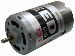
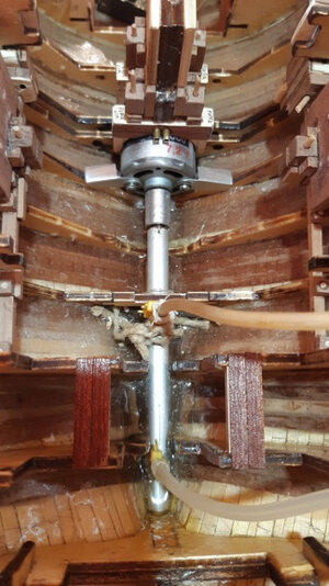
Scelta e posizione del motore.
Ho scelto questo motore qui:
GRAUPNER Speed 600
Operating voltage range 3,6...8,4 V
85 A
Diameter 35,8 mm
Free shaft length 8,7 mm
Case length 57 mm
All-up weight, approx. 235 g
Maximum efficiency 69 %
No-load current drain (A) 2 A
Charging rate at max. efficiency 12 A
Permissible motor direction R und L
No-load speed 18200 U/min
Nominal voltage 7,2 V
Shaft diameter 3,17 mm
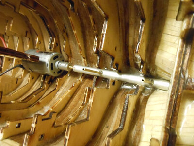
L'attacco all'asse dell'elica è diretto, senza ingranaggi nè riduzioni.
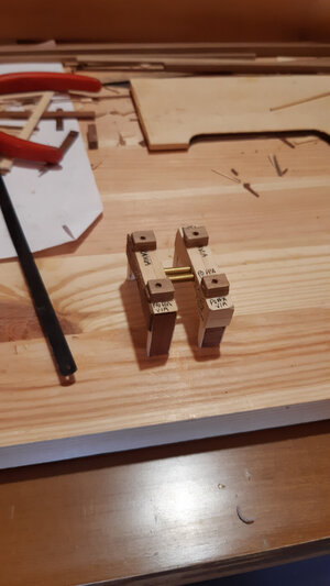
Per essere sicuro che i "grani" del giunto bloccassero efficacemente sia l'asse del motore sia l'asse dell'elica, ho limato entrambi, creando una superfice liscia invece che rotonda.
Il motore è sicuramente sovradimensionato per la grandezza e il tipo del modello, infatti, alla massima potenza, va troppo veloce per una navigazione realistica.
Allora perchè ho scelto un motore così potente e senza ingranaggi di riduzione, ma con attacco diretto sull'asse dell'elica ?
Ho ragionato così:
Per una navigazione realistica, e quindi lenta, agisco sul radiocomando (baso tutto sullo stick e sulla curva dell'accelleratore).
Però se ho bisogno di potenza in caso di necessità e portare a riva la nave anche con vento sfavorevole, posso contare su un buon motore.
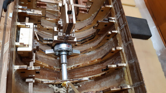
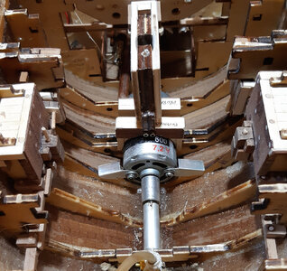
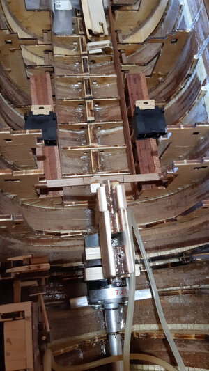
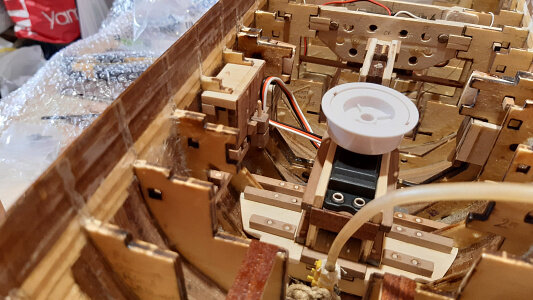
Il motore è collocato sotto l'albero di maestra. Quello che vedete sopra è un supporto per bloccarlo. Non è incollato.
In caso di avaria del motore è fatto in modo che possa essere tolto.
Però questa operazione è molto complessa.
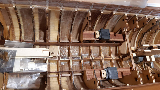
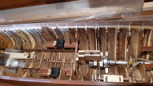
Per le batterie ho scelto batterie al piombo del tipo AGM da 6 volt e 4,5 Ah.
L'alloggiamento delle batterie (a proravia del motore) è previsto per questa tipologia, ma possono andarci anche quelle più piccole logicamente.
Lo spazio è creato per due batterie al centro nave con un certo margine per spostarle avanti e indietro e regolare l'assetto longitudinale.
Se non sbaglio, dividendo la nave in quattro parti lungo l'asse longitudinale, se si riesce a trovare un assetto con i quarti alle estremità, il peso che poi si inserirà nei due quarti centrali sarà poco influente.
In altre parole, le aggiunte di peso successive è meglio collocarle al centro della nave.
Greetings to all members
Choice and location of the engine.
I chose this engine here:
GRAUPNER Speed 600
The connection to the propeller shaft is direct, without gears or reductions.
To ensure that the joint "grains" effectively clamped both the motor shaft and the propeller shaft, I filed both, creating a smooth surface rather than a round one.
The engine is certainly oversized for the size and type of the model, in fact, at maximum power, it goes too fast for realistic navigation.
So why did I choose such a powerful engine without reduction gears, but with direct attachment to the propeller shaft?
I reasoned like this:
For realistic, and therefore slow, navigation, I use the radio control (I base everything on the stick and the accelerator curve).
But if I need power in case of emergency and to bring the ship to shore even in unfavorable winds, I can count on a good engine.
The engine is located under the main mast. What you see above is a support to block it. It is not glued.
In case of engine failure it is made so that it can be removed.
But this operation is very complex.
For the batteries I chose 6 volt, 4.5 Ah AGM lead acid batteries.
The battery compartment (forward of the engine) is intended for this type, but logically smaller ones can also fit there.
Space is created for two batteries amidships with some margin to move them fore and aft and adjust the longitudinal trim.
If I'm not mistaken, by dividing the ship into four parts along the longitudinal axis, if you manage to find a trim with the quarters at the ends, the weight that will then be inserted into the two central quarters will have little influence.In other words, subsequent weight additions are best placed amidships.



Wow!Un saluto a tutti i membri:
Scelta e posizione del motore.
Ho scelto questo motore qui:
GRAUPNER Speed 600
Operating voltage range 3,6...8,4 V
85 A
Diameter 35,8 mm
Free shaft length 8,7 mm
Case length 57 mm
All-up weight, approx. 235 g
Maximum efficiency 69 %
No-load current drain (A) 2 A
Charging rate at max. efficiency 12 A
Permissible motor direction R und L
No-load speed 18200 U/min
Nominal voltage 7,2 V
Shaft diameter 3,17 mm
L'attacco all'asse dell'elica è diretto, senza ingranaggi nè riduzioni.
Per essere sicuro che i "grani" del giunto bloccassero efficacemente sia l'asse del motore sia l'asse dell'elica, ho limato entrambi, creando una superfice liscia invece che rotonda.
Il motore è sicuramente sovradimensionato per la grandezza e il tipo del modello, infatti, alla massima potenza, va troppo veloce per una navigazione realistica.
Allora perchè ho scelto un motore così potente e senza ingranaggi di riduzione, ma con attacco diretto sull'asse dell'elica ?
Ho ragionato così:
Per una navigazione realistica, e quindi lenta, agisco sul radiocomando (baso tutto sullo stick e sulla curva dell'accelleratore).
Però se ho bisogno di potenza in caso di necessità e portare a riva la nave anche con vento sfavorevole, posso contare su un buon motore.
Il motore è collocato sotto l'albero di maestra. Quello che vedete sopra è un supporto per bloccarlo. Non è incollato.
In caso di avaria del motore è fatto in modo che possa essere tolto.
Però questa operazione è molto complessa.
Per le batterie ho scelto batterie al piombo del tipo AGM da 6 volt e 4,5 Ah.
L'alloggiamento delle batterie (a proravia del motore) è previsto per questa tipologia, ma possono andarci anche quelle più piccole logicamente.
Lo spazio è creato per due batterie al centro nave con un certo margine per spostarle avanti e indietro e regolare l'assetto longitudinale.
Se non sbaglio, dividendo la nave in quattro parti lungo l'asse longitudinale, se si riesce a trovare un assetto con i quarti alle estremità, il peso che poi si inserirà nei due quarti centrali sarà poco influente.
In altre parole, le aggiunte di peso successive è meglio collocarle al centro della nave.
Greetings to all members
Choice and location of the engine.
I chose this engine here:
GRAUPNER Speed 600
The connection to the propeller shaft is direct, without gears or reductions.
To ensure that the joint "grains" effectively clamped both the motor shaft and the propeller shaft, I filed both, creating a smooth surface rather than a round one.
The engine is certainly oversized for the size and type of the model, in fact, at maximum power, it goes too fast for realistic navigation.
So why did I choose such a powerful engine without reduction gears, but with direct attachment to the propeller shaft?
I reasoned like this:
For realistic, and therefore slow, navigation, I use the radio control (I base everything on the stick and the accelerator curve).
But if I need power in case of emergency and to bring the ship to shore even in unfavorable winds, I can count on a good engine.
The engine is located under the main mast. What you see above is a support to block it. It is not glued.
In case of engine failure it is made so that it can be removed.
But this operation is very complex.
For the batteries I chose 6 volt, 4.5 Ah AGM lead acid batteries.
The battery compartment (forward of the engine) is intended for this type, but logically smaller ones can also fit there.
Space is created for two batteries amidships with some margin to move them fore and aft and adjust the longitudinal trim.
If I'm not mistaken, by dividing the ship into four parts along the longitudinal axis, if you manage to find a trim with the quarters at the ends, the weight that will then be inserted into the two central quarters will have little influence.In other words, subsequent weight additions are best placed amidships.
View attachment 398051
View attachment 398052
View attachment 398053
View attachment 398054
View attachment 398055
View attachment 398056
View attachment 398057
View attachment 398058
View attachment 398059
View attachment 398060
- Joined
- Sep 3, 2021
- Messages
- 5,199
- Points
- 738

Thanks for your reply.Ciao Johan (RDN1954).
No, non è una domanda sciocca. Anzi molto arguta e intelligente, come tutti i messaggi che hai fatto finora.
La zavorra ci sarà, la farò vedere in successive foto, ma non voglio creare dei messaggi giganteschi con troppe foto e quindi illeggibili.
Te lo anticipo un pò.
Considera che, anche senza zavorra, il modello finito era ben bilanciato e aveva una buona spinta raddrizzante laterale.
Buona, ma non fortissima, quindi con venti forti al traverso forse sarebbe stato in difficoltà.
Ero riuscito ad ottenere questo risultato con la disposizione dei pesi utili (non zavorre).
Con l'applicazione della zavorra ho ottenuto una spinta raddrizzante laterale veramente efficace.
Indovina, se vuoi, dove e come ho messo la zavorra.
Hi (Johan) RDN1954.
No, it's not a silly question. Indeed very witty and intelligent, like all the messages you have made so far.
The ballast will be there, I will show it in subsequent photos, but I don't want to create gigantic messages with too many photos and therefore unreadable.
I'll give you a heads up a bit.
Consider that, even without ballast, the finished model was well balanced and had good lateral righting thrust.
Good, but not very strong, so with strong crosswinds perhaps he would have been in difficulty.
I managed to achieve this result with the arrangement of useful weights (not ballasts).
With the application of the ballast I obtained a truly effective lateral straightening thrust.
Guess, if you want, where and how I put the ballast.
Still not entirely satisfied though: you mentioned you needed a total mass of 5kg of the hull to respect your waterline. I assume the ballast is included in that figure. Is that a correct assumption?
I'm not an expert in RC models, but if I were to build a model like this I would like to have the required ballast as low as possible in the hull, rather evenly spread out.
I have seen RC models with a rather large false keel added to the keel of the model, but unfortunately I find that kind of cheating.
- Joined
- Sep 3, 2021
- Messages
- 5,199
- Points
- 738

Good evening Allessandro,
Again a very extensive description of the installation of the drive train, very informative.
Still, I find myself wondering why you positioned the engine underneath the main mast, insteadd of a little more aft, thus easing accessibility and simplifying the main mast support. Was the length of the axle the driving factor?
- Joined
- Sep 22, 2023
- Messages
- 238
- Points
- 213

Hi Johan.Thanks for your reply.
Still not entirely satisfied though: you mentioned you needed a total mass of 5kg of the hull to respect your waterline. I assume the ballast is included in that figure. Is that a correct assumption?
I'm not an expert in RC models, but if I were to build a model like this I would like to have the required ballast as low as possible in the hull, rather evenly spread out.
I have seen RC models with a rather large false keel added to the keel of the model, but unfortunately I find that kind of cheating.
You don't have to thank me, it's a pleasure for me to answer you.
It's exactly what you wrote.
Ballast is included in the total calculation of 5 kg.
In fact, the 5 kg represent the displacement of the ship, i.e. its total weight.
The total weight corresponds to the weight (approximately) of 5 dm3 (i.e. 5 litres) of fresh water.
The 5 dm3 correspond to the submerged volume of the ship up to the expected waterline.
Excellent.
"I have seen RC models with a rather large false keel added to the keel of the model, but unfortunately I find that kind of cheating."
No offense to anyone, I think exactly like you.
In fact, I wanted to build the model without "false keel added to the keel of the model".
Perhaps you are not an expert in dynamic RC modeling, but you have hit the crux of the matter perfectly, well done.
The weight should be kept as low as possible.
Now I don't want to get confused with the technical terms.
Technically, if it is possible to obtain "shape stability", the ship (even the real ones logically) manages to right itself within a certain angle of heel.
Almost all ships (warships, ocean liners, ferries, freighters, etc. etc.) have "stability of form".
If "weight stability" is achieved, the ship always rights itself at any angle of heel.
In form stability, the ship's center of gravity is above its hull center, and it has a righting thrust as long as the metacentric height is positive.
The higher the metacenter the better.
In weight stability the center of gravity is under the center of the hull.
At the end of the day: "The weight must be kept as low as possible."
In my model, I would have liked, already in the design phase with the 3D software, to verify and obtain weight stability.
During the construction phase I obtained an excellent straightening thrust.
Then you will see it with a very explicit video.
I hope I haven't made any confusion.If you or others have doubts because I explained myself poorly, it will only be my pleasure to try to explain myself better.
- Joined
- Sep 22, 2023
- Messages
- 238
- Points
- 213

Hi Johan.Good evening Allessandro,
Again a very extensive description of the installation of the drive train, very informative.
Still, I find myself wondering why you positioned the engine underneath the main mast, insteadd of a little more aft, thus easing accessibility and simplifying the main mast support. Was the length of the axle the driving factor?
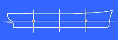
I positioned the engine a little further forward because I wanted to find a longitudinal arrangement with the fixed elements, then leaving the mobile elements, i.e. the batteries, a certain margin. For a final adjustment.
For this reason I needed the very heavy engine later on.
If we divide the ship into four along the longitudinal axis, we have seen that, by stabilizing the ship with the weights placed in the most extreme quarters, the weight that is then introduced into the internal quarters has little influence on the trim.
But I was wrong. You're right.
Then weighing the pros and cons there are more cons. (Then weighing the advantages and disadvantages, there are more disadvantages). In fact, the engine under the tree creates a lot of problems for me in case of replacement.
I hope the translation conveyed the concept well, if not please tell me.
Hi Alessandro,Quando ho intrapreso il progetto avevo pochissime conoscenze nautiche.
Per il progetto ho usato il programma 3d Rhinoceros, che ho imparato (solo parzialmente) per questa esigenza.
Inizialmente, la classe USS Unadilla mi è servita solo come punto di partenza;
Man mano che la costruzione procedeva, pur seguendo il mio progetto per lo scafo e la parte dinamica, cercavo sempre più particolari e dettagli per una ricostruzione coerente.
Nel link video e nelle immagini potete vedere alcuni degli aspetti salienti del progetto.
In estrema sintesi dal disegno della ciglia e delle linee principali ho creato (con moltissime difficoltà) la superficie dello scafo. dalla suferice dello scafo, ho creato le varie ordinate che ho posizionato su vari fogli per il successivo taglio.
When I undertook the project I had very little nautical knowledge.
For the project I used the 3D program Rhinoceros which I learned (only partially) for this need.
Initially, the USS Unadilla class only served as a starting point for me;
As the construction progressed, while following my project for the hull and the dynamic part, I was looking for more and more details for a coherent reconstruction.
In the video link and in the images you can see some of the salient aspects of the project.
In a nutshell, from the design of the eyelash and the main lines I created (with great difficulty) the surface of the hull. from the surface of the hull, I created the various frames which I positioned on various sheets for subsequent cutting.
View attachment 396445
View attachment 396446
View attachment 396447
View attachment 396448
View attachment 396449
View attachment 396450
View attachment 396451
View attachment 396452
View attachment 396453
View attachment 396454
I am a bit late to catch up your build-log. I am impressed by what you have drawn in Rhinoceros. With the final result of the lasered plates including the bulkheads.
I am trying to get the same results with Fushion 360 for my new build.
I'm quite proficient in Photoshop, but learning a new 3D program takes time. Fortunately, I now get help from a friend who works with AutoCAD in luxury yacht building. He likes the fact that what he used to have to draw by hand on the truss floor, many many years ago, he can now work out in CAD with my old drawing of the line plan.
The hull of your ship turned out beautiful.
Although I have nothing to do with RC, I am impressed with what you are building in now.
Regards, Peter
- Joined
- Sep 22, 2023
- Messages
- 238
- Points
- 213

Salve a tutti.
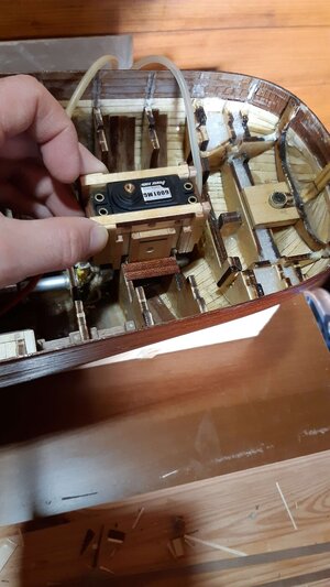
Il lavoro del modello è proseguito con la costruzione di un alloggiamento per il verricello del timone.
Ho preferito creare una struttura amovibile perchè, in caso di guasto e sostituizione, è molto più facile sfilare tutto il pezzo che dover svitare le viti del servomeccanismo.
Non pensate allo scafo come si vede ora tutto libero e facile da gestire. Con il ponte i movimenti sono molto limitati.
Prima di costruire il pezzo, ho dovuto ricreare le ortogonalità all'interno dello scafo con dei quadrelli di rinforzo.
Il pezzo amovibile potete vederlo in questo brevissimo video:
Hello everyone.
Model work continued with the construction of a housing for the rudder winch.
I preferred to create a removable structure because, in the event of failure and replacement, it is much easier to remove the entire piece than having to unscrew the screws of the servomechanism.
Don't think about the hull as you can see it now, all free and easy to manage. With the bridge, movements are very limited.
Before building the piece, I had to recreate the orthogonalities inside the hull with reinforcing squares.
You can see the removable piece in this very short video.
Grazie dei bellissimi complimenti.
Il disegno 3d non è facile, sto piano piano recuperando le conoscenze.
Sono molto contento che lavori anche tu in 3d.
Ho sentito parlare di Fushion 360 ma non l'ho mai usato.
Spero che tu ottenga ottimi risultati e tante soddisfazioni.
Hi Peter.
Thanks for the beautiful compliments.
3D drawing is not easy, I'm slowly recovering the knowledge.
I'm very happy that you work in 3D too.
I've heard of Fushion 360 but have never used it.
I hope you get excellent results and lots of satisfaction.
Il lavoro del modello è proseguito con la costruzione di un alloggiamento per il verricello del timone.
Ho preferito creare una struttura amovibile perchè, in caso di guasto e sostituizione, è molto più facile sfilare tutto il pezzo che dover svitare le viti del servomeccanismo.
Non pensate allo scafo come si vede ora tutto libero e facile da gestire. Con il ponte i movimenti sono molto limitati.
Prima di costruire il pezzo, ho dovuto ricreare le ortogonalità all'interno dello scafo con dei quadrelli di rinforzo.
Il pezzo amovibile potete vederlo in questo brevissimo video:
Hello everyone.
Model work continued with the construction of a housing for the rudder winch.
I preferred to create a removable structure because, in the event of failure and replacement, it is much easier to remove the entire piece than having to unscrew the screws of the servomechanism.
Don't think about the hull as you can see it now, all free and easy to manage. With the bridge, movements are very limited.
Before building the piece, I had to recreate the orthogonalities inside the hull with reinforcing squares.
You can see the removable piece in this very short video.
Ciao Pietro.Hi Alessandro,
I am a bit late to catch up your build-log. I am impressed by what you have drawn in Rhinoceros. With the final result of the lasered plates including the bulkheads.
I am trying to get the same results with Fushion 360 for my new build.
I'm quite proficient in Photoshop, but learning a new 3D program takes time. Fortunately, I now get help from a friend who works with AutoCAD in luxury yacht building. He likes the fact that what he used to have to draw by hand on the truss floor, many many years ago, he can now work out in CAD with my old drawing of the line plan.
The hull of your ship turned out beautiful.
Although I have nothing to do with RC, I am impressed with what you are building in now.
Regards, Peter
Grazie dei bellissimi complimenti.
Il disegno 3d non è facile, sto piano piano recuperando le conoscenze.
Sono molto contento che lavori anche tu in 3d.
Ho sentito parlare di Fushion 360 ma non l'ho mai usato.
Spero che tu ottenga ottimi risultati e tante soddisfazioni.
Hi Peter.
Thanks for the beautiful compliments.
3D drawing is not easy, I'm slowly recovering the knowledge.
I'm very happy that you work in 3D too.
I've heard of Fushion 360 but have never used it.
I hope you get excellent results and lots of satisfaction.
- Joined
- Sep 22, 2023
- Messages
- 238
- Points
- 213

Hello everyone.
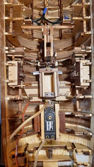
Model work continued with the construction of a housing for the rudder winch.
I preferred to create a removable structure because, in the event of failure and replacement, it is much easier to remove the entire piece than having to unscrew the screws of the servomechanism.
Don't think about the hull as you can see it now, all free and easy to manage. With the bridge, movements are very limited.
Before building the piece, I had to recreate the orthogonalities inside the hull with reinforcing squares.
You can see the removable piece in this very short video:
At his time I thought a lot about whether it would be better to control all the sails with a single winch or to use more.
I had even thought about three winches.
At that time I didn't have access to all the information I might have today.
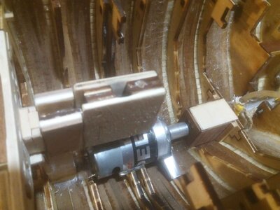
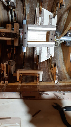
I also created a removable wooden seat for the winch.
The reasons are the same.
This one was a little more complicated and has a strange shape.
You can see the removable piece in this very short video:
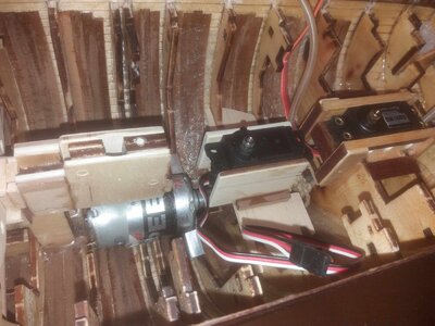
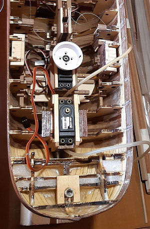
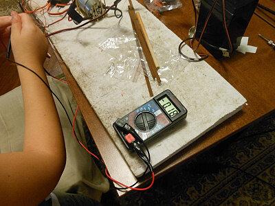
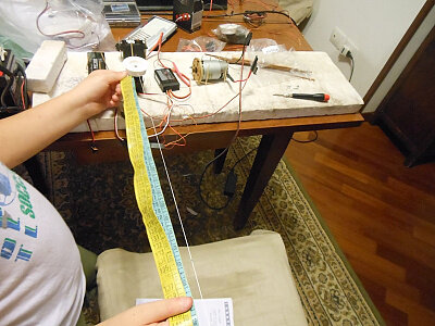
I did some electrical tests with the winches, helped by my son.
They were tests to check both the electrical absorption and to see how much wire he could wind.
Initially I was happy that it wrapped 36 cm of wire.
Since I had never done a job like this I thought it was good. In reality, this much thread would have given me problems later.
In fact, to go from slack gait to upwind pace, much less cm is needed on my model.


- Joined
- Sep 22, 2023
- Messages
- 238
- Points
- 213

Ciao Johan, poi mi sono ricordato un altro motivo, ancora più importante, per cui il motore è così in avanti, perdonami.Good evening Allessandro,
Again a very extensive description of the installation of the drive train, very informative.
Still, I find myself wondering why you positioned the engine underneath the main mast, insteadd of a little more aft, thus easing accessibility and simplifying the main mast support. Was the length of the axle the driving factor?
Oltre al discorso dei pesi, considera che quel punto è praticamente obbligato se si vuole tenere il motore più in basso possibile e avere due verricelli anzichè uno solo.
Più indietro, anche di pochi cm, avrebbe significato mancanza di spazio per il verricello di poppa. Se posizionato sopra al motore sarebbe uscito fuori dal deck.
In basso non può stare perchè, più a poppa si va e più le ordinate salgono e diventano strette.
Mi ricordo ora che questo lo verificai già in fase di disegno 3D, che in questo caso mi ha aiutato molto.
Hi Johan, then I remembered another, even more important reason why the engine is so forward, forgive me.
In addition to the issue of weights, consider that that point is practically obligatory if you want to keep the engine as low as possible and have two winches instead of just one.
Further back, even by a few cm, would have meant lack of space for the stern winch. If positioned above the engine it would have come out of the deck.
It can't stay at the bottom because the further aft you go, the more the frames rise and become narrower.
I remember now that I verified this already during the 3D drawing phase, which in this case helped me a lot.
Last edited:
- Joined
- Sep 3, 2021
- Messages
- 5,199
- Points
- 738

Wow, quite a few imposed requirements on the engine location. Very nicely handled though.Ciao Johan, poi mi sono ricordato un altro motivo, ancora più importante, per cui il motore è così in avanti, perdonami.
Oltre al discorso dei pesi, considera che quel punto è praticamente obbligato se si vuole tenere il motore più in basso possibile e avere due verricelli anzichè uno solo.
Più indietro, anche di pochi cm, avrebbe significato mancanza di spazio per il verricello di poppa. Se posizionato sopra al motore sarebbe uscito fuori dal deck.
In basso non può stare perchè, più a poppa si va e più le ordinate salgono e diventano strette.
Mi ricordo ora che questo lo verificai già in fase di disegno 3D, che in questo caso mi ha aiutato molto.
Hi Johan, then I remembered another, even more important reason why the engine is so forward, forgive me.
In addition to the issue of weights, consider that that point is practically obligatory if you want to keep the engine as low as possible and have two winches instead of just one.
Further back, even by a few cm, would have meant lack of space for the stern winch. If positioned above the engine it would have come out of the deck.
It can't stay at the bottom because the further aft you go, the more the frames rise and become narrower.
I remember now that I verified this already during the 3D drawing phase, which in this case helped me a lot.
If I would have been in your shoes, I might have taken it as far as to locate the engine slightly left or right of center as to not disrupt the main mast installation and accepting the usage of the rudder while sailing under engine to keep her on even keel.
- Joined
- Sep 22, 2023
- Messages
- 238
- Points
- 213

Ciao Johan.Wow, quite a few imposed requirements on the engine location. Very nicely handled though.
If I would have been in your shoes, I might have taken it as far as to locate the engine slightly left or right of center as to not disrupt the main mast installation and accepting the usage of the rudder while sailing under engine to keep her on even keel.
Si hai ragione, spostare a sinistra o a destra il motore poteva essere una soluzione valida.
Il motore non in asse, mi avrebbe però costretto ad usare degli ingranaggi e non avrei potuto collegare l'albero motore direttamente all'asse dell'elica, come ho fatto.
Non che questo sia un problema, anzi molti modellisti dinamici preferiscono sempre mettere degli ingranaggi, perchè questi aumentano la forza, ma soprattutto riducono la velocità. Ridurre la velocità è importante per effettuare una navigazione RC realistica. Infatti vedere un motoveliero o un piroscafo a vapore che va veloce come un motoscafo , può essere divertente ma non certo realistico.
Per questo la tua osservazione è molto appropriata.
Io non ho preso in considerazione questa opzione, quando ero in fase di progetto, perchè, per motivi di spazio, avevo preferito rinunciare agli ingranaggi. Inoltre, per questioni di simmetria, ho voluto mettere tutto perfettamente centrato.
I tuoi interventi sono molto graditi perchè intellettualmente stimolanti e mi fanno ricordare molte cose che avevo dimenticato.
L'alloggiamento dell'albero di poppa è abbastanza profondo da garantire la sua stabilità anche senza incollarlo.
Hi Johan.
Yes, you are right, moving the engine to the left or right could have been a valid solution.
However, the engine not being aligned would have forced me to use gears and I would not have been able to connect the drive shaft directly to the propeller axis, as I did.
Not that this is a problem, in fact many dynamic modelers always prefer to use gears, because these increase strength, but above all reduce speed.
Reducing speed is important for realistic RC navigation. In fact, seeing a motor sailing vessel or a steamer that goes as fast as a motorboat may be fun but certainly not realistic.
This is why your observation is very appropriate.
I did not take this option into consideration when I was in the design phase because, for reasons of space, I had preferred to do without the gears.
Furthermore, for reasons of symmetry, I wanted to put everything perfectly centered.
Your interventions are very welcome because they are intellectually stimulating and make me remember many things that I had forgotten.
The aft mast housing is deep enough to ensure its stability even without gluing it.
Alessandro, great job on the hull, it looks beautiful. I can't wait for this boat to soar across the water! Magic Mike
Very impressive project. I like the idea that you didn’t give up when faced with a challenge.Buona sera (o buon giorno) a tutti.
Una volta ottenute le frames, la chiglia e i ponti per il taglio, ho inziato a lavorare manualmente.
Per essere più veloce, decisi di provare per la prima volta il taglio laser, invece del classico seghetto a traforo (seghetto ad arco).
Sono andato da un amico che lo usava per la prima volta sul legno compensato da 4 mm di spessore.
Il risultato è stato disastroso, invece di un taglio perfetto ha bruciato tutti i bordi.
Volevo buttare tutto e ricominciare, invece ho deciso di proseguire. Sarebbe stato meglio rifare il taglio ma il legno da buttare era molto.
Vi sto spiegando questo perchè vedrete le ordinate con i segni di bruciato.
Il risultato è stato che le frames "ballavano" sulla chiglia, invece di incastrarsi perfettamente, come avrebbero dovuto.
Nelle immagini potete vedere anche la predisposizione per un regolo per allineare ulteriormente tutte le ordinate.
Insomma, ho dovuto faticare tantissimo e spendere molto più tempo per curare la giusta posizione di ogni frame.
Iniziavamo proprio male.
I cerchi e i quadrati che vedete sulle singole ordinate, sono i pretagli per far passare cavi o elementi di rinforzo come quadrelli di legno.
Le forme strane sono gli alloggiamenti per il motore, gli alberi., ecc. ecc. In seguito sarà tutto più chiaro.
Una volta finito il fasciame dello scafo, la parte interna delle frames andra tolto e rimarranno solo delle sottili costole.
Good evening (or good morning) everyone.
Once I had the frames, the keel and the decks for cutting I started working manually.
To be faster, I decided to try laser cutting for the first time, instead of the classic fret saw (bow saw).
I went to a friend who was using it for the first time on 4mm thick plywood.
The result was disastrous, instead of a perfect cut it burned all the edges.
I wanted to throw everything away and start again, but instead I decided to continue.
It would have been better to redo the cut but there was a lot of wood to throw away.
I'm explaining this to you because you will see the frames with burn marks.
The result was that the frames "danced" on the keel, instead of fitting together perfectly, as they should have.
In the images you can also see the provision for a ruler to further align all the ordinates.
In short, I had to work a lot and spend a lot more time getting the right position for each frame.
We started off really badly.
The circles and squares that you see on the individual frames are the pre-cuts for passing cables or reinforcing elements such as wooden squares.
The strange shapes are the engine housings, the shafts, etc. etc.
Everything will be clearer later.
Once the hull plating is finished, the internal part of the frames will be removed and only thin ribs will remain.
I hope I was understandable.
View attachment 396595
View attachment 396596
View attachment 396597
View attachment 396598
View attachment 396599
View attachment 396600
View attachment 396601
View attachment 396602
View attachment 396603
View attachment 396604
View attachment 396605
I wish I’d known about this tool 35 years ago when I built my only plank on frame model boat. I opted for building plastic models after that, only because my career got more involved and I didn’t have the time to devote. I’ve got so much respect for the craftsmanship of the members on here.Le tue osservazioni sono corrette.
Considera, però, che molte scelte sono state fatte quando le mie conoscenze erano molto limitate. In fase di realizzazione ho acquisito man mano molte informazioni da libri e su internet (testi, immagini e video).
Oggi sono soddisfatto solo di alcune scelte tecniche che ho adottato, anche se inconsuete, ma molte scelte sono invece da evitare, oggi non le rifarei.
Per quanto riguarda le "bending pliers" , non ne ho avuto bisogno finchè gli scafi dei modelli avevano un " transom" piatto. In questo caso, come dici tu giustamente: "le curvature sembrano essere piuttosto benigne".
In questo modello la poop, invece, è tonda e le curvature sono molto accentuate, bisogna fare addirittura un cerchio sui listelli più vicini al ponte.
Per non spezzarli si possono usare molti metodi: la candela, il vapore, l'acqua bollente ecc. ecc. Tutti medoti molto laboriosi e lunghi secondo me.
La pinza piegalistelli è geniale per quanto semplice, piega il listello grazie a delle tacche che fa sul legno, senza spezzarlo.
Più sono fitte le tacche che si fanno tanto più la curvatura del listello di legno è accentuata. Le tacche sono antiestetiche (brutte a vedersi), ma non c'è problema, perchè capitano sempre nella parte concava e quindi non sono visibili.
E' incredibile quanto tardi ho scoperto questo strumento che tutti conoscevano.
Your observations are correct.
Consider, however, that many choices were made when my knowledge was very limited.
During the creation phase I gradually acquired a lot of information from books and on the internet (texts, images and videos).
Today I am only satisfied with some of the technical choices I have adopted, even if they are unusual, but many choices are to be avoided and I wouldn't do them again today.
As for the bending pliers, I didn't need them as long as the model hulls had a flat transom.
In this case, as you rightly say: "the curvatures appear to be rather benign".
In this model, however, the poop is round and the curvatures are very accentuated, you even have to make a circle on the slats closest to the bridge.
To avoid breaking them, many methods can be used: candle, steam, boiling water, etc. etc. All very laborious and time-consuming methods in my opinion.
The strip bending pliers are ingenious yet simple, they bend the strip thanks to the notches they make on the wood, without breaking it.
The denser the notches are made, the more accentuated the curvature of the wooden strip is.
The notches are unsightly (unsightly), but there is no problem, because they always occur in the concave part and therefore are not visible.It's amazing how late I discovered this tool that everyone knew about.
View attachment 396685
- Joined
- Sep 22, 2023
- Messages
- 238
- Points
- 213

Grazie Magic Mike!Alessandro, great job on the hull, it looks beautiful. I can't wait for this boat to soar across the water! Magic Mike
Arriverà quel momento che andrà sull'acqua.
Thanks Magic Mike!
There will come that time that he will go on the water.

