Ciao a tutti i modellisti navali.
Nei primi video potete vedere alcune prove di assorbimento elettrico a basso numero di giri e senza impedimenti (a parte l'attrito di questo fluido che chiamiamo acqua).
Purtroppo non li ho documentati tutti. Prove motore, prove di vibrazione e prove timone a basso numero di giri.
Gli altri, con rotazioni forzate, non sono documentati ma, se volete credermi, si sono comportati abbastanza bene da indurmi a proseguire con la costruzione.
L'amperometro era protetto fino a 10 ampere poi è stato rimosso.
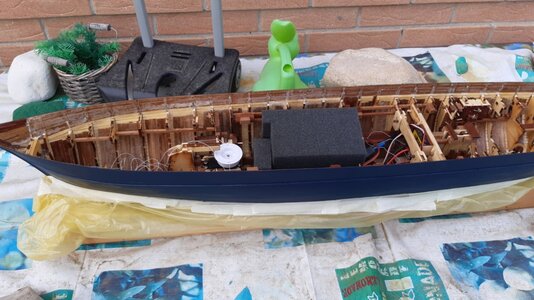
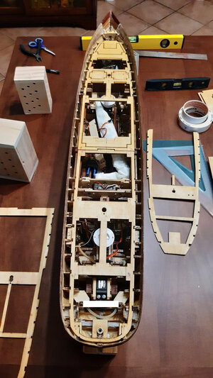
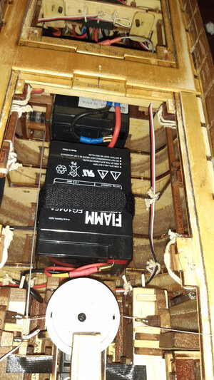
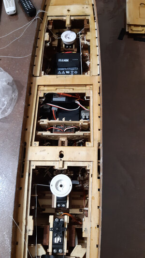
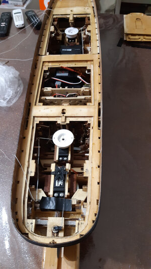
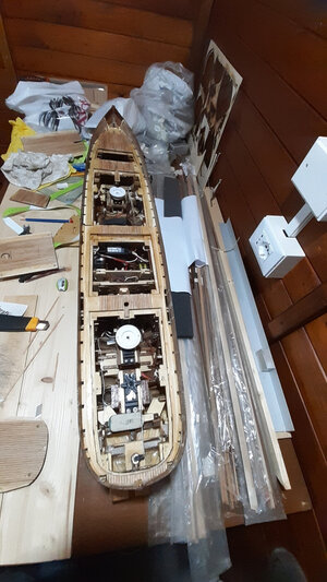
Naturalmente non fate caso al caos dei cavi, poi sono stati accorciati e disposti in ordine simmetrico.
I cavi più pesanti si trovano in basso nelle apposite guide pretagliate dei telai e quelli più piccoli sono posizionati lungo i quadri longitudinali di rinforzo.
Seguono i video delle prove a secco dell'elica e del timone.
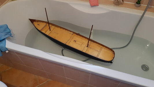
Poi ci sono i video di altri test di stabilità laterale quasi a pieno carico.
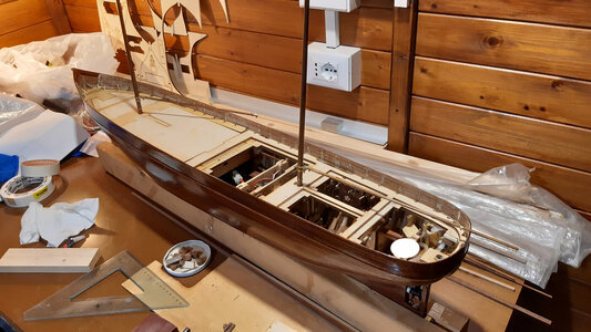
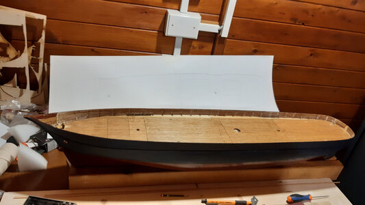
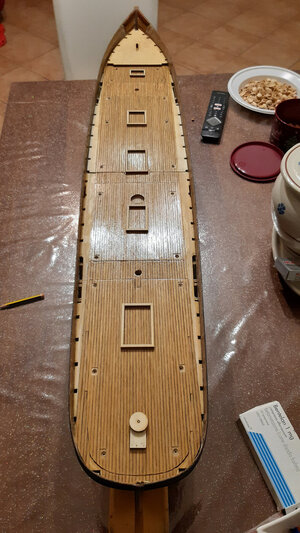
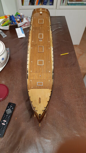
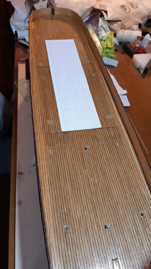
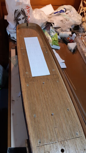
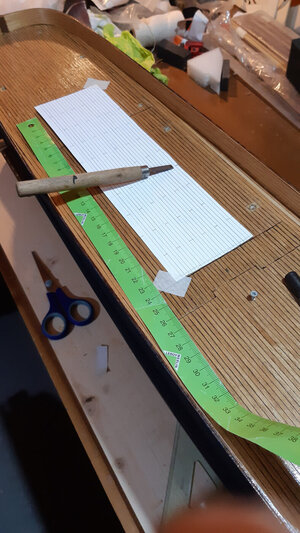
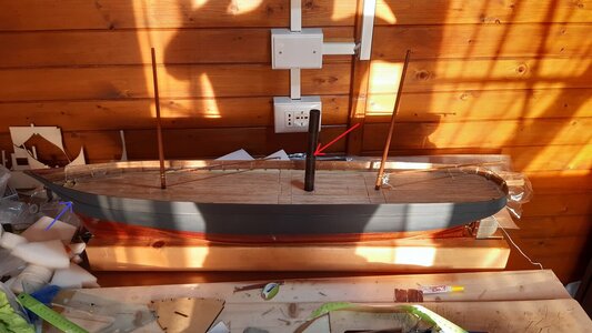
In questo post vorrei mostrarvi anche come ho realizzato i ponti.
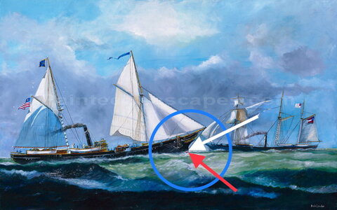
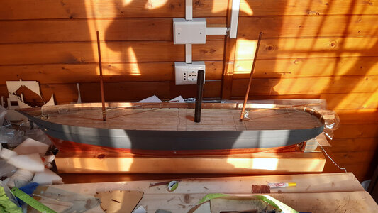
Come avrete già capito, questa tipologia di vaporiere non presenta sovrastrutture sulle murate atte a nascondere i coperchi.
Chi fa modellismo statico non ha affatto il problema dei coperchi. Ma i modellisti dinamici sanno bene che l’accesso per cambiare le batterie o sostituire eventuali parti rotte deve essere garantito.
Le sovrastrutture sono una mano santa, beato chi le possiede.
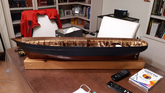
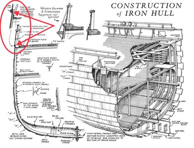
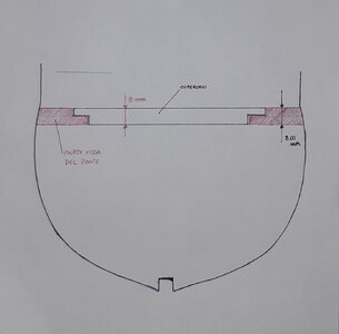
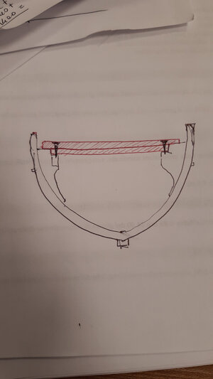
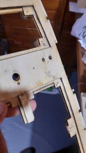
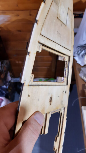
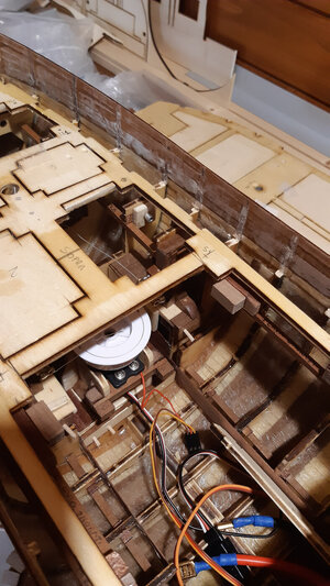
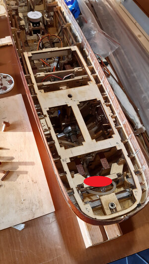
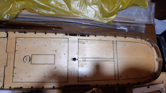
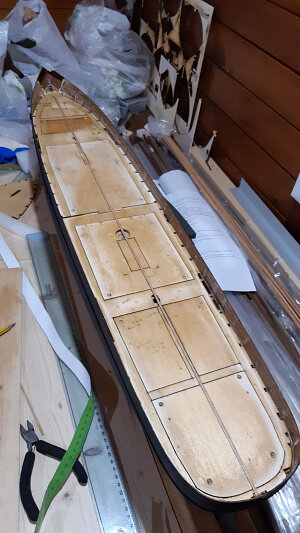
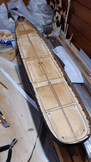
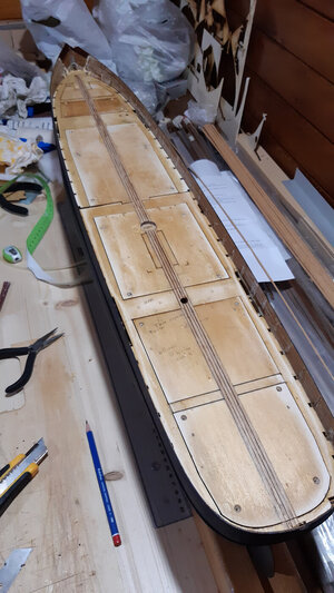
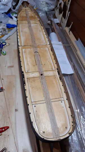
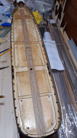
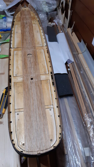
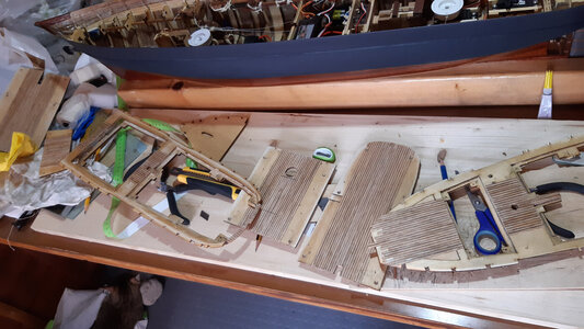
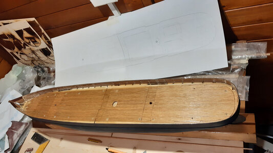
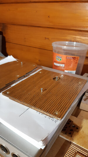
Ho utilizzato due fogli di compensato sovrapposti come si vede nel disegno e come si vede nelle foto, in modo che i coperchi poi si incastrino.
In pratica ho creato uno scalino sia sul deck che sul coperchio.
I coperchi saranno tutti fissati con viti per legno. Ho scoperto che le viti sono superflue perchè il doppio fermo permette una chiusura molto stabile.
Non potevo saperlo in anticipo.
Le viti non vengono solo avvitate nel compensato, che sarebbe troppo sottile e troppo fragile, ma in un supporto prefilettato e molto robusto in legno. Le sedi delle viti sono rinforzate da piccoli imbuti di plastica incollati (precauzione forse del tutto superflua).
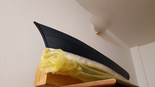
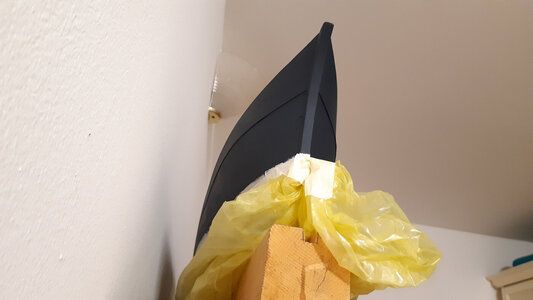
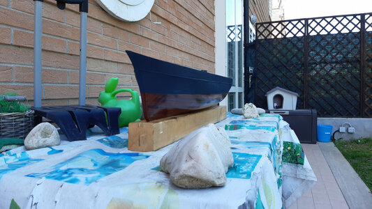
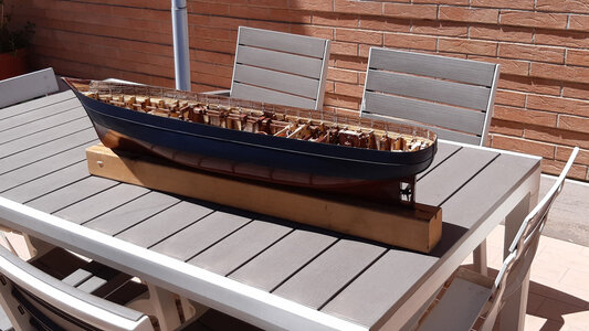
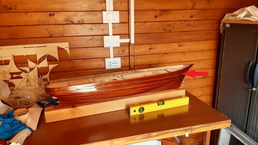
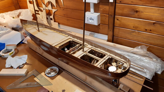
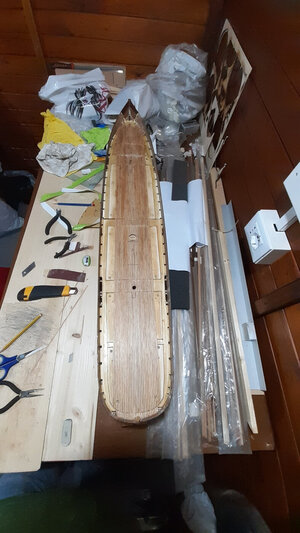
Inizialmente, come potete vedere dal confronto delle prime foto con le ultime, avevo previsto (stupidamente) molte aperture sulla coperta, ma molto piccole. Non ci ho messo molto a capire che tante aperture avrebbero rovinato ancora di più i listelli della coperta e non mi avrebbero permesso di infilare nemmeno una mano nella stiva del modello (che è maledettamente piccolo per tutto quello che deve fare).
Tuttavia, una volta incollati i doppi piani, il modello risulta molto robusto.
Solo l'impavesata è ancora molto delicata ma lo vedremo più avanti.
Abbiate pazienza ancora molta parte dinamica ma presto verranno elementi prettamente di modellismo statico.
Hello to all naval modelers.
In the first videos you can see some tests of electrical absorption at low rpm and without impediments (apart from the friction of this fluid that we call water).
Unfortunately I haven't documented them all.
Engine tests, vibration tests and rudder tests at low rpm.
The others, with forced rotations, are not documented but, if you want to believe me, it performed well enough to induce me to continue with the construction.
The ammeter was protected up to 10 amps then it was removed.
Don't pay attention to the chaos of cables, of course, they were then shortened and arranged in symmetrical order. The heaviest cables are at the bottom in the special pre-cut guides of the frames and the smaller ones are positioned along the longitudinal reinforcement squares.
The videos of the dry tests of the propeller and rudder follow.
Then there are videos of other lateral stability tests almost at full load.
In this post I would also like to show you how I made the decks.
As you may have already understood, this type of steamer does not have any superstructures on the topsides which are suitable for hiding the lids.
Those who do static modeling do not have the problem of lids at all. But dynamic modelers know well that access to change batteries or replace any broken parts must be guaranteed.
The superstructures are a holy hand, blessed is he who has them.
I used two overlapping sheets of plywood as seen in the drawing and as seen in the photos, so that the lids then fit together.
In practice I created a step on both the deck and the lid.
The lids will all be secured by wood screws. I found that screws are superfluous because the double stop allows for a very stable fit. I couldn't have known in advance.
The screws are not only screwed into plywood, which would be too thin and too fragile, but into a pre-threaded and very wooden sturdy support. The screw sockets are reinforced by small glued plastic funnels (perhaps a completely superfluous precaution).
Initially, as you can see from the comparison of the first photos with the last ones, I had foreseen (stupidly) many openings on the deck, but very small ones. It didn't take long for me to realize that so many openings would have ruined the deck slats even more and wouldn't have allowed me to even insert a hand into the hold of the model (which is damned small for everything it has to do).
However, once the double decks have been glued, the model is very robust.
Only the handrail is still very delicate but we will see later.
https://www.youtube.com/watch?v=u7f5J8TD1Zk[/MEDIA]
https://www.youtube.com/watch?v=zK2rilCkJGw[/MEDIA]
https://www.youtube.com/watch?v=jgsgrPSu1ns[/MEDIA]
View attachment 402165
View attachment 402166
View attachment 402167
View attachment 402168
View attachment 402169
View attachment 402170
View attachment 402171
View attachment 402172
View attachment 402173
View attachment 402174
View attachment 402175
View attachment 402176
View attachment 402177
View attachment 402178


