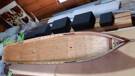
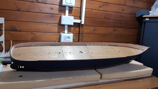
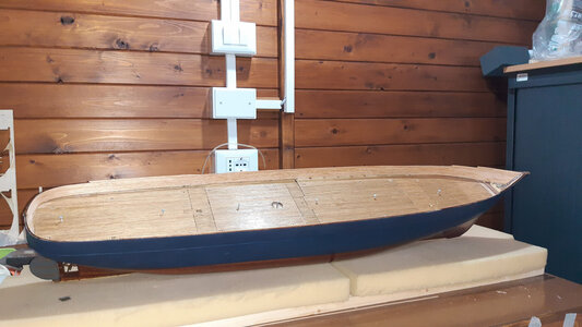
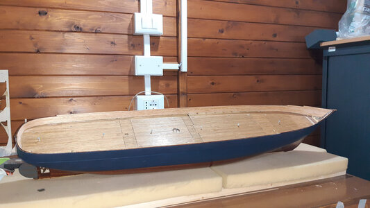
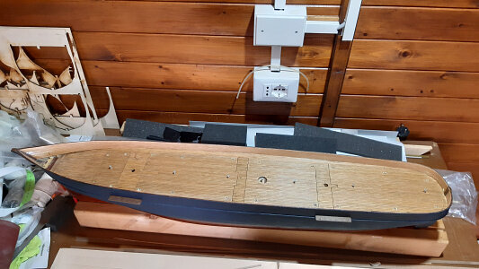
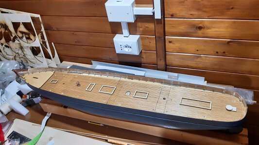
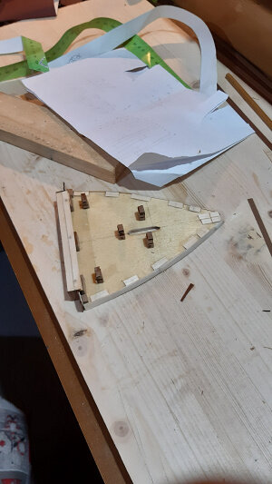
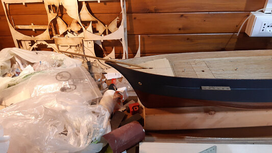
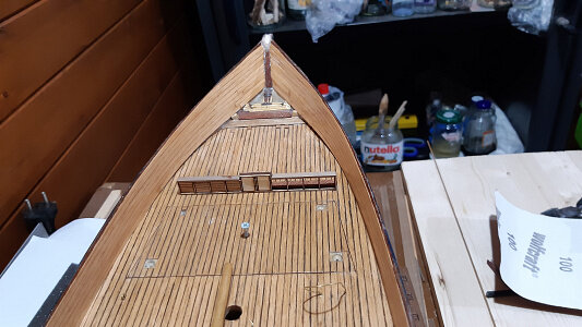
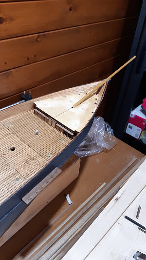
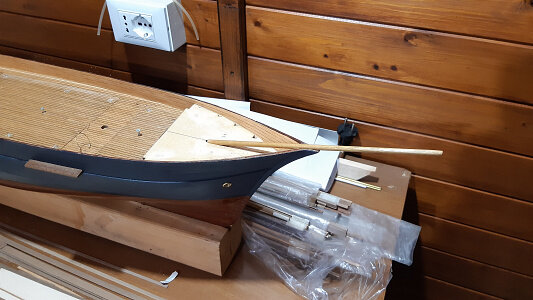
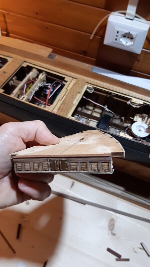
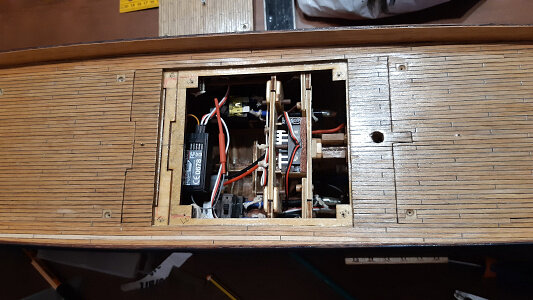
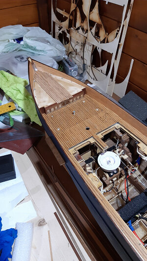
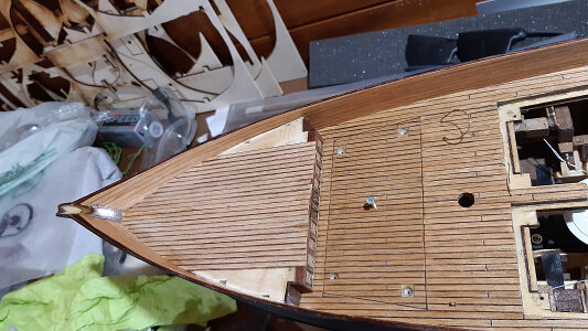
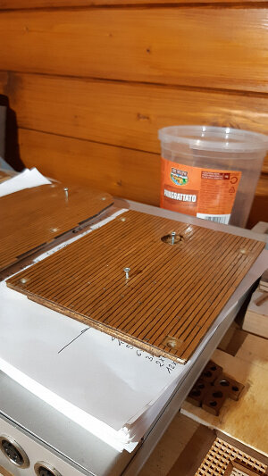
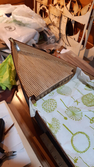
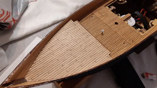
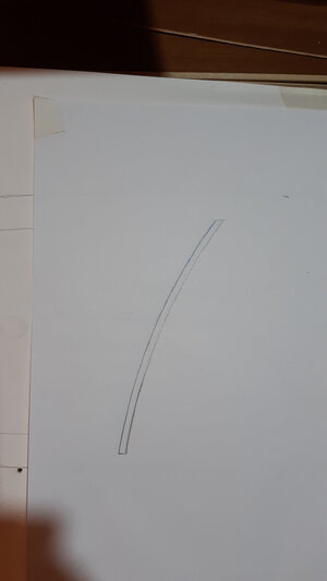
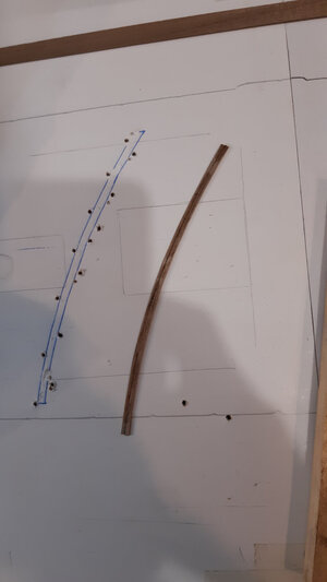
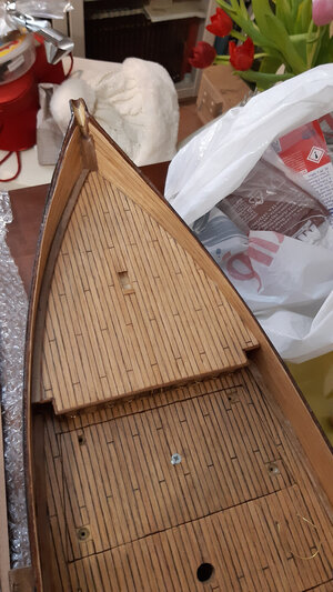
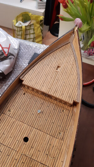
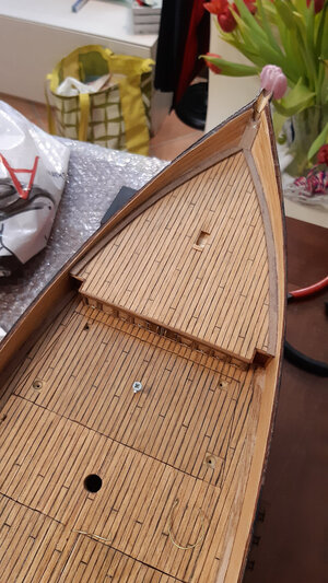
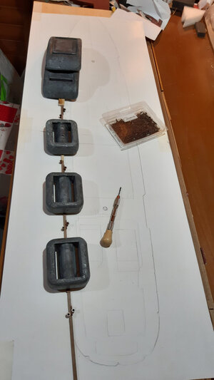
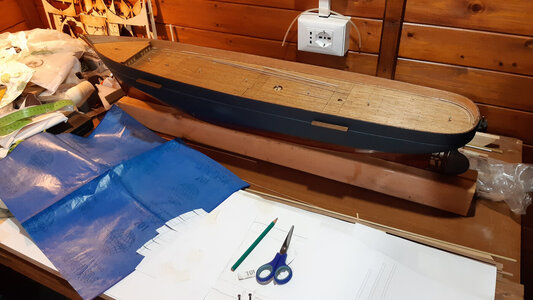
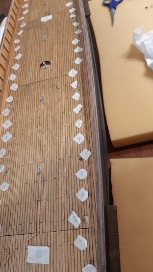
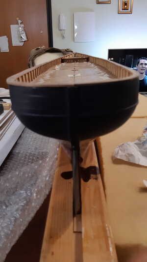
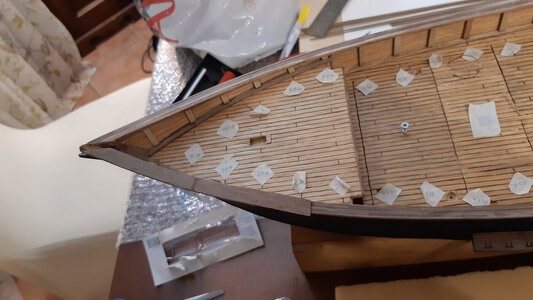
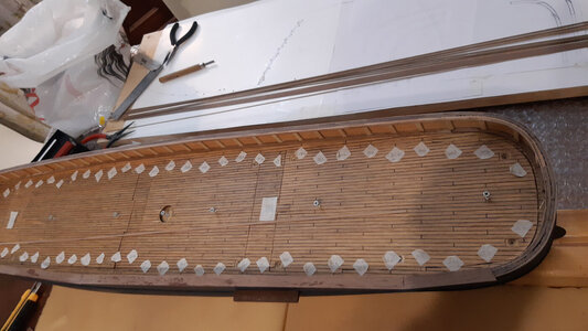
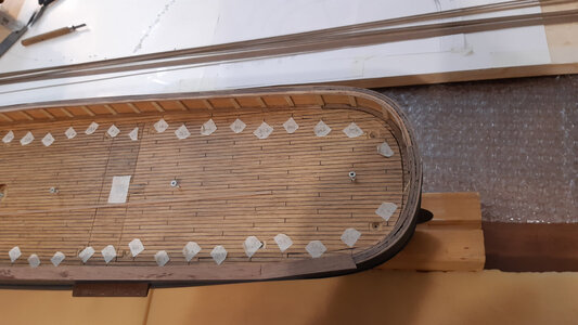
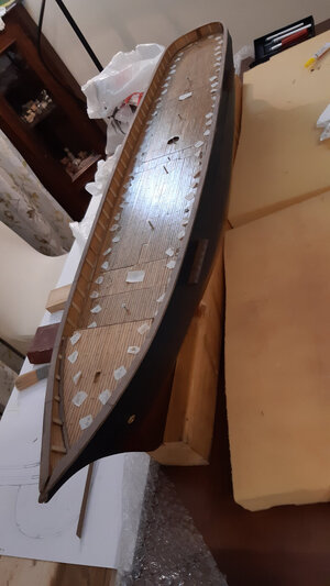
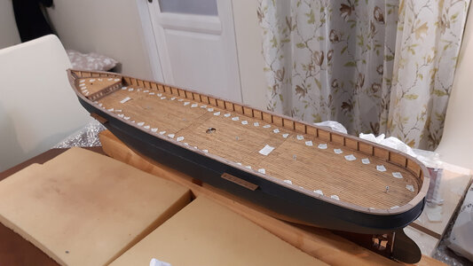
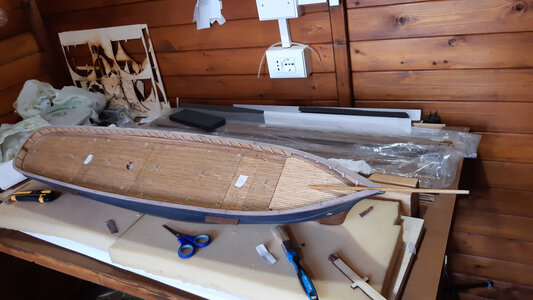
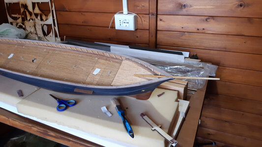
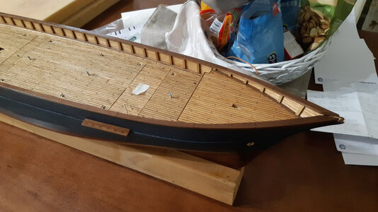
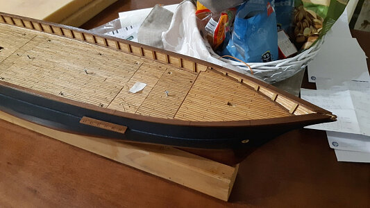
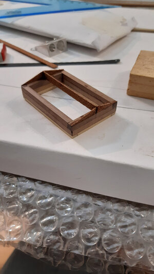
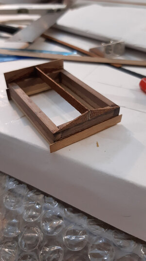
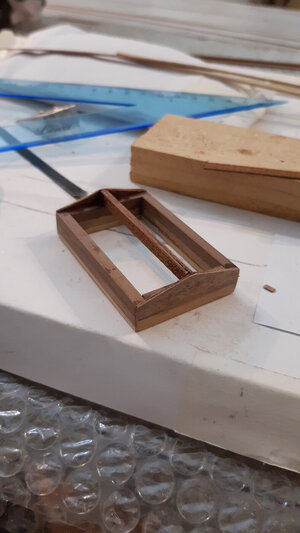
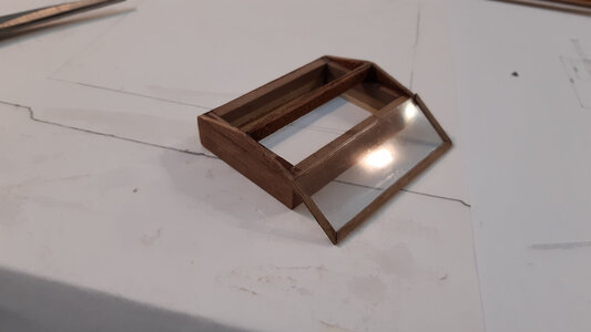
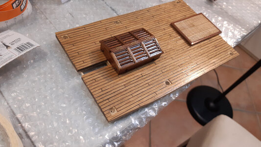
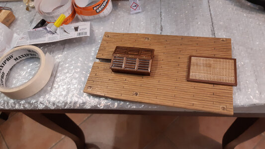
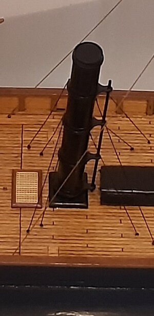
1/60 scale RC model of a schooner, loosely based on a gunboat steamship from the second half of the 19th century.

Buona sera a tutti.

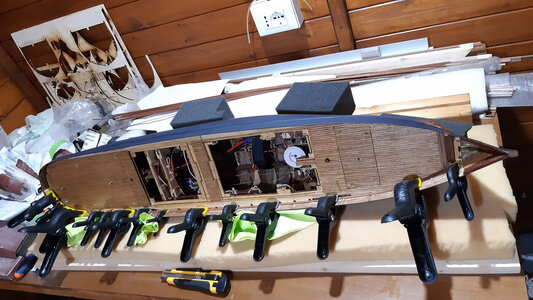
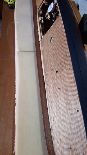
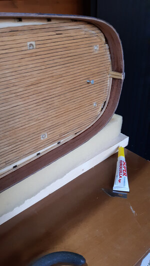
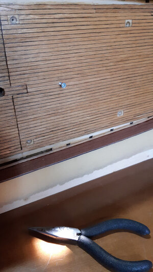
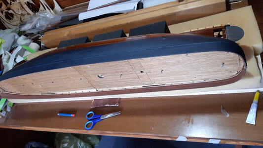
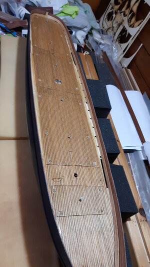
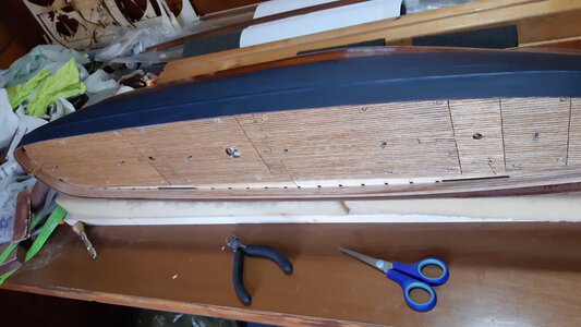
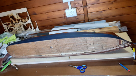
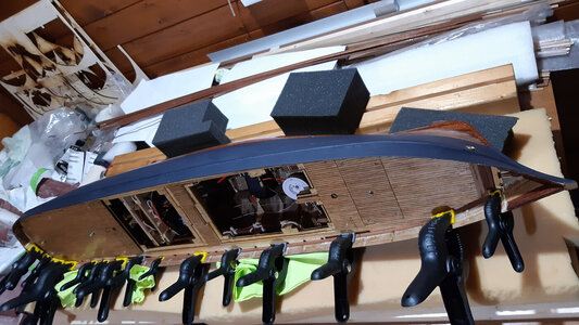
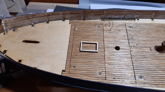
Le foto che seguono mostrano le fasi di rinforzo dell'impavesata con listelli di mogano e poi con listelli di noce tanganika nella parte interna.

Per essere precisi questa fase è precedente all'intaglio delle assi sul ponte.

Good evening everyone

The following photos show the phases of reinforcing the handrail with mahogany strips and then with Tanganyika walnut strips on the internal part.
To be precise, this phase is prior to carving the planks onto the deck.


impavesata1.jpg

impavesata2.jpg

3impavesata.jpg

4impavesata.jpg

5impavesata.jpg

6impavesata.jpg

7impavesata.jpg

8impavesata.jpg

9impavesata.jpg

10impavesata.jpg

11impavesata.jpg

12impavesata.jpg

13impavesata.jpg

14impavesata.jpg

15impavesata.jpg

15impavesata.jpg
 
Last edited:
Ciao Norway, Anatoly, Johan, Peter e Jimsky.
Se voi insistete a mettere "mi piace", io insisto nel ringraziarvi, ahahahahaha!

Hello Norway, Anatoly, Johan, Peter and Jimsky.If you insist on "liking", I insist on thanking you, ahahahahaha!
 
Buona sera a tutti.

Le foto che seguono mostrano le fasi di rinforzo dell'impavesata con listelli di mogano e poi con listelli di noce tanganika nella parte interna.

Per essere precisi questa fase è precedente all'intaglio delle assi sul ponte.

Good evening everyone

The following photos show the phases of reinforcing the handrail with mahogany strips and then with Tanganyika walnut strips on the internal part.
To be precise, this phase is prior to carving the planks onto the deck.


View attachment 403082

View attachment 403083

View attachment 403084

View attachment 403085

View attachment 403086

View attachment 403087

View attachment 403088

View attachment 403089

View attachment 403090

View attachment 403091

View attachment 403092

View attachment 403093

View attachment 403094

View attachment 403095

View attachment 403096

View attachment 403097
Apart from "liking" what you're accomplishing, I still have questions...
From your pictures I deduced that you're using some type of wood screw to secure the access hatches to the hull. Wouldn't it be more sensible to use inserts and countersunk bolts (that is with normal thread) to secure your hatches with? My view on it is that a normal thread with a nut/insert is much more durable than a wood screw engaging in wood.
Ciao Johan, le domande mi fanno sempre piacere.
E quanto mi piace parlare di argomenti di modellismo!
E' bello costruire ma poi anche commentare.

Che posso dire? : le tue domande fanno sempre centro.

Questo è un aspetto che ho valutato a lungo e, a suo tempo, ho ascoltato il parere di un modellista dinamico che faceva esattamente le tue stesse osservazioni.

"normal thread with a nut/insert is much more durable than a wood screw engaging in wood". E' sicuro al cento per cento che sia proprio così.

Allora mi chiederai: "perchè hai comunque usato le viti a legno?"

Partiamo da una premessa che vale per questo tuo giusto quesito ma vale per tutto il topic.
In questa fase stiamo parlando ancora di soluzioni già adottate.
Le mie scelte non sono le migliori, alcune non le rifarei.
Avevo pensato anche a una chiusura con magneti.

La risposta è molto semplice: in molte circostanze ho cercato la via più veloce (o almeno quella che mi sembrava più veloce).
Preparare una filettattura in cui far entrare la vite e cercare le viti adatte mi è sembrato più complicato.
Certi lavori a me sembrano difficili e lunghi anche se ad altre persone risultano semplici e veloci.
Io ci ho messo molto, troppo tempo per realizzare il modello con pause molto lunghe.

Ho pensato: compro delle viti piccole, leggere, standard che potrei ritrovare in qualsiasi negozio in qualsiasi momento.
Creo dei tasselli di legno robusti e spessi in cui entrerà la vite, basterà fare un foro poco più piccolo della vite a legno e poi sarà lei a creare da sola la filettatura.
Come fare a non rovinare la filettatura essendo di solo legno?
Ingrassando la vite e facendo attenzione quando avvito.
Considera che le aperture sono molto limitate, solo i portelli centrali vanno aperti per inserire/togliere le batterie.
Gli altri saranno usati solo nel caso di avarie.

Considera che i coperchi (ma questo l'ho scoperto solo dopo averli fatti) non avrebbero alcun bisogno della vite, non si aprirebbero nemmeno capovolgendo la nave.
Ma ormai le ho messe e le uso. Uso le viti perchè comprimono meglio le superfici a battuta (quel famoso scalino) per cui è previsto comunque un leggero strato di grasso per la tenuta stagna.
Non si può pensare che il ponte non sia inondato di acqua durante la navigazione con forte vento al traverso.

E se la filettatura si rovina lo stesso?
Qualora la filettatura sia totalmente compromessa e inultilizzabile, posso sempre fare un foro cilindrico da 6 o 8 mm di diametro , infilare un tondino di noce dello stesso diametro, incollarlo e poi rifilettarlo con la vite a legno, ma non credo ce ne sarà bisogno.

Attenzione. alcune viti che hai visto nelle foto solo solo temporanee e mi sono servite per aprire i coperchi in mancanza di altri appigli per le dita.
Poi questa funzione verrà assunta dall'argano, dall'osteriggio ecc. ecc. Ogni coperchio avrà la sua "maniglia".


Hi Johan, questions always make me happy.
And how much I love talking about modeling topics!It's nice to build but then also comment.

What can I say? : your questions always hit the mark.

This is an aspect that I have considered for a long time and, at the time, I listened to the opinion of a dynamic modeller who made exactly the same observations as you.
"normal thread with a nut/insert is much more durable than a wood screw engaging in wood". He is one hundred percent sure that this is indeed the case.

Then you'll ask me, "Why did you use wood screws anyway?"

Let's start from a premise that applies to this right question of yours but applies to the entire topic.
At this stage we are still talking about solutions already adopted.
My choices are not the best, some I wouldn't make again.
I had also thought about a closure with magnets.

The answer is very simple: in many circumstances I have looked for the fastest way (or at least the one that seemed fastest to me).
Preparing a thread for the screw to fit into and looking for suitable screws seemed more complicated to me.
Some jobs seem difficult and long to me even if to other people they seem simple and quick.
It took me a long, long time to make the model with very long pauses.

I thought: I'll buy some small, lightweight, standard screws that I could find in any store at any time.
I create sturdy and thick wooden dowels into which the screw will fit, just make a hole a little smaller than the wood screw and then it will create the thread itself.
How can you avoid ruining the thread as it is only made of wood?Greasing the screw and being careful when screwing.
Consider that the openings are very limited, only the central doors need to be opened to insert/remove the batteries.
The others will be used only in the event of failure.

Consider that the lids (but I discovered this only after having made them) would not need the screw at all, they would not open even by turning the vessel upside down.
But now I have them and use them. I use screws because they compress the abutment surfaces better (that famous step) for which a light layer of grease is required for watertightness.
It cannot be assumed that the bridge is not flooded with water while sailing in strong crosswinds.

What if the thread gets ruined anyway?
If the thread is totally compromised and unusable, I can always make a cylindrical hole of 6 or 8 mm in diameter, insert a walnut rod of the same diameter, glue it and then rethread it with the wood screw, but I don't think there will be any need.

Attention. Some screws that you saw in the photos were only temporary and were used to open the lids in the absence of other grips for my fingers.
Then this function will be taken over by the winch, skylight etc. etc.
Each lid will have its own "handle".
 
Wow, that's an extensive reply to an innocent looking question!

I guess I understand your rationale, but to say that I'm convinced is pushing it.
My experiences with woodscrews are such that I'll only use them in permanent applications. Anything that need to be removed more than once will see the application of screw threaded bolts and nuts.
There are a lot of standard solutions available for nearly any application. But having said that, if you're happy with your solution, go with it and like you said, repairs are possible.
Beh, no Johan, completamente soddisfatto no.

Il tuo sistema sarebbe stato senz'altro migliore.

Diciamo che ho visto una scorciatoia in un momento di stasi, e l'ho presa.
Tieni presente che per ogni elemento ho dovuto prendere una decisione, ero sempre ad un bivio e alla ricerca di informazioni: quanto era largo questo? e quanto era lungo? usavano già questo a quei tempi? Ecc. Ecc.

Mi sono dimenticato che a far pendere la bilancia dalla parte delle viti a legno è stato anche il peso.
Ho pensato che con le sole viti a legno avrei risparmiato un pò di peso strategico.
In effetti un certo risparmio c'è stato.

Col senno del poi, sono dell'idea che la tua sia la soluzione migliore.
 
Well, no Johan, not completely satisfied.


Your system would definitely have been better.

Let's say I saw a shortcut in a moment of stasis, and I took it.

Keep in mind that for each element I had to make a decision, I was always at a crossroads and looking for information: how wide was this? and how long was it? did they already use this back then? Etc. etc.


I forgot that it was also the weight that tipped the scales in favor of the wood screws.

I thought that with just the wood screws I would save some strategic weight.

In fact there was a certain saving.


In hindsight, I think yours is the best solution.
 
The focsle looks great, like the rest of your build.
It also looks as if you're cleaning up the under-deck system compartments.
 
Ciao Johan, ti ringrazio per l'interesse e l'apprezzamento.

Se tu indendi i cablaggi sottocoperta, si.
In molti videe o foto, soprattuto per le prove, i cavi elettrici erano messi alla rinfusa eerano molti di più del dovuto.

Una volta stabilito quale fosse il tipo di circuito, ho riordinato i cavi togliendo tutti quelli superflui, facendo passare i cavi più grossi in basso (nei buchi già pretagliati delle frames) e quelli più fini lungo i quadrelli di legno longitudinali di rinforzo.

Comunque (sempre se ho capito bene) mi fa piacere che hai notato un milioramente dell''ordine li sotto. Era inguardabile prima.


Hi Johan, thank you for your interest and appreciation.

If you compete the Lowerdeck wiring, yes.

In many videos or photos, especially for the tests, the electrical cables were put in bulk and many more than they should.

Once established what the type of circuit was, I reorganized the cables by removing all the superfluous ones, passing the larger cables below (in the already pre -paved holes of the frames) and the finest ones along the longitudinal wooden squares of reinforcement.

Anyway (always if I understand correctly) I am pleased that you have noticed a military one of the order below. It was unwatchable before.
 
Ciao a tutti.

Le foto seguenti rappresentano la costruzione del trincarino.

Non era facile piegare quel listello di noce.
Non potevo usare il disegno 3D di Rhinoceros per riportare la traversa su carta in 2D, perché avevo apportato troppe modifiche durante la costruzione.
Le modifiche consistevano nel rinforzare la prua con diversi strati di listelli.
Quindi ho utilizzato un metodo empirico che potete vedere con la sequenza delle foto.
Forse è meglio così che una descrizione difficile.
A poppa il pezzo non era un pezzo unico ma diversi pezzi tagliati.


Hi everyone.

The following photos represent the construction of the stringer.
It wasn't easy to bend that walnut strip.

I couldn't use Rhinoceros' 3D drawing to bring the stringer back to paper in 2D, because I had made too many changes during construction.
The modifications consisted of reinforcing the bow with several layers of battens.
So I used an empirical method that you can see with the sequence of photos.
Maybe it's better this way than a difficult description.
At the stern the piece was not a single piece but several cut pieces.


trincarino1.jpg

trincarino2.jpg

trincarino3.jpg

trincarino4.jpg

trincarino5.jpg

trincarino6.jpg

trincarino67jpg.jpg

trincarino8jpg.jpg

trincarino9jpg.jpg

trincarino10jpg.jpg

trincarino11jpg.jpg

trincarino12jpg.jpg

trincarino13jpg.jpg
 
Salute a tutti.
Volevo illustrare alcune fasi che potrebbero essere interessanti per chi non le ha mai fatte e potrebbero darmi un'alternativa al metodo di lavorazione.
Ho sempre l'impressione di non scegliere la tecnica migliore o quella più veloce.
Accetto volentieri ogni suggerimento.

Ecco come ho proceduto per Capodibanda "Gunwales" (per non creare malintesi sulle parole lo indico con una freccia rossa):
Purtroppo non trovo le foto che mostrano le varie strisce, ho paura di aver sovrascritto i file.
Dato che non sarei mai riuscito a piegare un listello così largo, ho creato i capodibanda unendo tre listelli di noce più piccoli a sezione quadrata.
Puoi vedere il disegno a penna.
I tre quadrelli di noce, logicamente, erano stati piegati per seguire la forma della baluardo (freccia verde).
Il capodibanda è incollato alla murata. La falchetta è più sporgente della murata.
Sulla parte interna, visto che si vedevano gli antiestetici segni della piegatura, ho incollato una striscia molto sottile (0,5 mm) e quindi molto facile da piegare.
Restava da ricoprire la parte sovrastante con una striscia molto larga (8-10 mm) e molto sottile (0,5 mm), per non mostrare l'antiestetica unione delle tre strisce quadrate di noce.
Non potendo curvare quest'ultima striscia, è stata tagliata in vari pezzi.
Le unioni si vedono solo a prua e a poppa (frecce gialle).
Poi ho tagliato e incollato gli Scalmotti (Futtock, Timber, Bulwark Stanchion?), indicati nella foto con la freccia blu.
Se ho sbagliato i termini degli elementi indicati con le frecce correggetemi.
Per il momento salto la descrizione delle parasartie (Channel?) indicate con la freccia nera, perché poi dovevo rifarle.
Posso anticipare che nel progetto li avevo messi troppo in là. Poi osservando migliaia di foto, di navi dell'epoca, mi sono reso conto che quella era la posizione sbagliata.
Ma questo è un argomento importante della tecnica navale velica e vorrei parlarne a parte.

Health to all.

I wanted to illustrate some phases that may be interesting for those who have never done them and could give me an alternative to the processing method.

I always have the impression of not choosing the best technique or the fastest.
I gladly accept every suggestion.

Here's how I proceeded for Capodibanda "Gunwales" (In order not to create misunderstandings on words I indicate it with a red arrow):

Unfortunately I do not find the photos showing the various slaughtered strips, I'm afraid of having overwritten the files.
Since I would never have managed to bend such a wide strip, I created the Gunwales by combining three smaller walnut strips with a square section. You can see the pen drawing.
The three square strips of walnut, logically, had been folded to follow the shape of the bulwark (green arrow).
Gunwales is glued on the bulwark. Gunwales is more protruding than the bulwark.
On the internal part, since the unsightly signs of the bending were seen, I glued a very thin strip (0.5 mm) and therefore very easy to bend.
It remained to cover the part above with a very wide (8-10 mm) and very thin (0.5 mm) strip, so as not to show the unsightly union of the three square strips of walnut.
Not being able to curve the latter strip, it has been cut into various pieces. The unions are seen only in the bow and aft (yellow arrows).

Then I cut and glued the Scalmotti (Futtock, Timber, Bulwark Stanchion?), Indicated in the photo with the blue arrow.

If I was wrong the terms of the elements indicated with the arrows please correct me.

For the moment I jump the description of the parasartie (Channel?) Indicated with the black arrow, because I then had to do them again.
I can anticipate that in the project I had put them too far. Then observing thousands of photos, ships of the time, I realized that that was the wrong position. But this is an intersery topic of sailing naval technique and I would like to talk about it aside.


a1n.jpg

a2n.jpg

a3n.jpg

a4n.jpg

a5.jpg

a7.jpg

a8n.jpg

a10n.jpg

a11n.jpg

a12n.jpg

a13n.jpg

a15.jpg

a16n.jpg

a17n.jpg

a18n.jpg

a20n.jpg

a20n.jpg

a21n.jpg

a22n.jpg

a23n.jpg

1001n.jpg

freccen.jpg

1005.jpg

1007n.jpg

1009.jpg
 
Last edited:
Health to all.

I wanted to illustrate some phases that may be interesting for those who have never done them and could give me an alternative to the processing method.

I always have the impression of not choosing the best technique or the fastest.
I gladly accept every suggestion.

Here's how I proceeded for Capodibanda "Gunwales" (In order not to create misunderstandings on words I indicate it with a red arrow):

Unfortunately I do not find the photos showing the various slaughtered strips, I'm afraid of having overwritten the files.
Since I would never have managed to bend such a wide strip, I created the Gunwales by combining three smaller walnut strips with a square section. You can see the pen drawing.
The three square strips of walnut, logically, had been folded to follow the shape of the bulwark (green arrow).
Gunwales is glued on the bulwark. Gunwales is more protruding than the bulwark.
On the internal part, since the unsightly signs of the bending were seen, I glued a very thin strip (0.5 mm) and therefore very easy to bend.
It remained to cover the part above with a very wide (8-10 mm) and very thin (0.5 mm) strip, so as not to show the unsightly union of the three square strips of walnut.
Not being able to curve the latter strip, it has been cut into various pieces. The unions are seen only in the bow and aft (yellow arrows).

Then I cut and glued the Scalmotti (Futtock, Timber, Bulwark Stanchion?), Indicated in the photo with the blue arrow.

If I was wrong the terms of the elements indicated with the arrows please correct me.

For the moment I jump the description of the parasartie (Channel?) Indicated with the black arrow, because I then had to do them again.
I can anticipate that in the project I had put them too far. Then observing thousands of photos, ships of the time, I realized that that was the wrong position. But this is an intersery topic of sailing naval technique and I would like to talk about it aside.
First of all, there's no "correct" way of building parts and components. More often than not it depends on the materials available, one's skills et, the tools one has to ones disposition, time and money.
Bending of a wide strip in plane is not easy, especially if there's a strong curvature. In that case it's either cutting/machining a piece of wood to shape, or follow your solution; bond various strips together in the required shape. Apparently you didn't bend the strips prior to bondig, hence the wrinkles and the subsequent need to cover up. Personally I would have made the bulwarks from wide, cut-to-shape parts, of appropriate length and where necessary, cut in multiple parts (lengthwise).

Your stanchions (scalmotti) look great and add credibility to the entire railing. Futtocks are parts of the frame construction, while the stanchions extended to above deck, to support the railing parts.

The position (and dimensions) of the channels should preferably be derived from the full scale drawings, if available.
Otherwise I would try and find information about the channels on contemporary and comparable ships.
Ciao Johan.

Stavolta sono riuscito a tradurre tutto al cento per cento.

Mi piacerebbe vedere il tuo metodo, se hai fatto foto intermedie del lavoro.
So che spesso le foto si fanno all'ultimo e non mentre si lavora, ma se le hai mi piacerebbe vederle per imparare alcuni metodi del modellismo.

Sono contento che gli stanchions ti piacciano. Ho fatto in modo che fosse allineati proprio dove iniziano le tavole del deck, in modo da rendere il tutto più realistico anche se molte persone non ci fanno caso. Nelle navi vere, infatti, le tavole venivano inchiodate dove c'era un supporto trasversale a sostenerle. Questo supporto trasversale corrispondeva allo stanchion.

Sono riuscito a creare dei channels proporzionati sia in larghezza che in spessore.
Quello che ho sbagliato è la loro posizione.
Nel mio progetto iniziale li avevo messi molto più avanti perchè volevo permettere al boma un movimento di quasi 90 gradi, per l'andatura di poppa.
Mettendoli più indietro avrei ridotto notevolmente il movimento del boma.
Eppure, con mia grande sorpresa, dopo lunghe e accurate ricerche, ho constatato che la posizione era ben più arretrata.
Il motivo è che le sartie maggiori, sulle navi vere, lavorano in contrapposizione sui fianchi per garantire la stibilità trasversale all'albero, ma stando indietro (in contrapposizione con gli stralli) garantiscono anche la stabilità longitudinale all'albero.
Questo (per le navi vere non certo per il mio modello) è prioritario rispetto alle possibilità di movimento del boma.
Avendolo scoperto troppo tardi, ho dovuto rompere tutto, channels, staffe, sartie, ecc. ecc. Erano complete.
E' stata una decisione difficile, ma sapendo che c'era un grosso errore non riuscivo ad andare avanti ignorandolo.


Hi Johan.

This time I managed to translate everything one hundred percent.

I'd love to see your method, if you took intermediate photos of the work.
I know that photos are often taken at the last minute and not while working, but if you have them I would like to see them to learn some modeling methods.

I'm glad you like the stanchions.
I made sure that it was aligned right where the deck boards start, to make everything more realistic even if many people don't notice.
In real ships, in fact, the boards were nailed where there was a transverse support to support them.
This transverse support corresponded to the stanchion.

I managed to create channels that were proportionate in both width and thickness.
What I got wrong is their position.In my initial project I had placed them much further forward because I wanted to allow the boom to move by almost 90 degrees, for the stern stroke.
By placing them further back I would have significantly reduced the movement of the boom.Yet, to my great surprise, after long and careful research, I found that the position was much further back.
The reason is that the major shrouds, on real ships, work in opposition to the sides to guarantee transversal stability to the mast, but being back (in contrast to the stays) they also guarantee longitudinal stability to the mast.
This (for real ships certainly not for my model) has priority over the possibilities of movement of the boom.Having discovered this too late, I had to break everything, channels, brackets, shrouds, etc. etc.
They were complete.It was a difficult decision, but knowing there was a big mistake I couldn't move forward and ignore it.
 
Un saluto a tutti i modellisti di questo forum.
Ora illustrerò come ho costruito alcuni elementi che si trovano sulla coperta.
Le immagini riguardano la realizzazione dell'osteriggio e delle scalette (che collegano il ponte di prua con il ponte principale).
Tralascio le fasi costruttive dei carabottini, li vedrete semplicemente comparire nelle immagini più recenti del ponte.
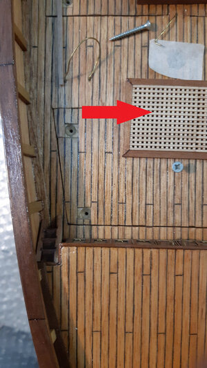
Per quest'ultimo vengono vendute piccole strisce con denti che devono essere unite tra loro. La parte più difficile è creare il contorno perfettamente quadrato.La griglia vista in foto, evidenziata con la freccia rossa, è obliqua (storta) perché è stata solo posizionata, non era ancora stata incollata.Per il lucernario la sequenza delle foto compensa bene un commento scritto.
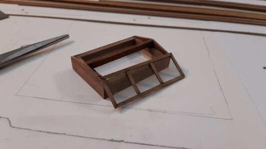
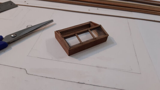
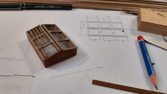
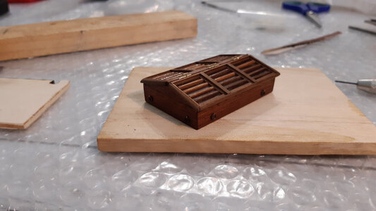
Ho progettato io stesso il lucernario, inventandolo, ma ho guardato molte foto sia di navi vere dell'epoca che di modelli in scala.
Per la scaletta volevo scrivere due righe riguardo il metodo utilizzato.
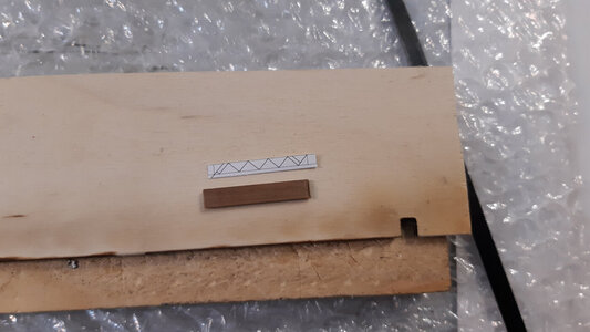
Potrebbe essere un suggerimento per altri modellisti.Per prima cosa ho provato a disegnare gli spazi per i gradini direttamente sul legno.
Tuttavia, l'unità più piccola su un quadrato o un righello è il millimetro.
Troppo grande per un oggetto così piccolo. In effetti era troppo impreciso e di conseguenza storto.
Il calibro non era pratico da utilizzare in questo contesto, quindi ho scelto di utilizzare Rhinoceros.
Ho creato il file pdf e l'ho stampato su carta.
Ho ritagliato le parti utili che ho incollato alle strisce.Infine ho tagliato il legno seguendo direttamente le linee del disegno.
Alla fine ho svolto il lavoro in meno tempo e con più precisione.
Probabilmente se avessi trovato delle scale già pronte in un negozio di modellismo le avrei comprate, ma non erano della misura che mi serviva.
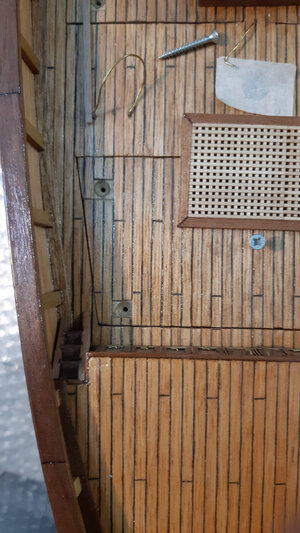
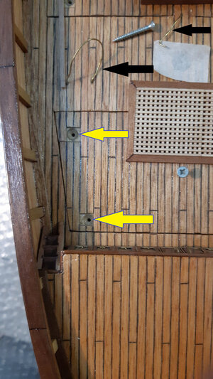
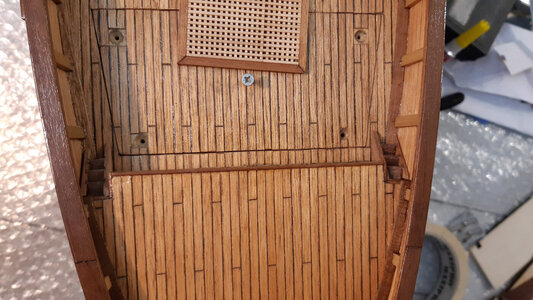
Oltre a verificare se altezza e larghezza fossero adatte al posizionamento sul modello, ho fatto attenzione che il gradino fosse in scala con quello reale.Le frecce gialle indicano i fori delle viti utilizzati per bloccare i coperchi.
Le viti (antiestetiche) verranno ingrassate e ricoperte.
Non saranno mai visibili una volta completato il modello.
Le frecce nere indicano i fili di ottone. I cavi di ottone vengono infilati nei fori dove passeranno le lastre.
I cavi in ottone servono per evitare che i fori (anch'essi in ottone) si incollino con colla e altri materiali durante le fasi di lavorazione.
Verranno rilasciati solo nelle fasi finali al passaggio delle lamiere.


Greetings to all the modelers on this forum.

I will now illustrate how I built some elements that are on the deck.

The images concern the construction of the skylight and the ladders (which connect the bow deck with the main deck).
I omit the construction phases of the gratings, you will simply see them appear in the most recent images of the bridge.
For the latter, small strips with teeth that must be joined together are sold. The hardest part is creating the perfectly square outline.

The grating seen in the photo, highlighted with the red arrow, is oblique (crooked) because it was only placed, it had not yet been glued.

For the skylight, the sequence of photos makes up for a written comment well. I designed the skylight myself, inventing it, but I looked at many photos of both real ships from that era and scale models.

For the lineup I wanted to write two lines about the method used.
It could be a tip for other modelers.

I first tried drawing the spaces for the steps directly on the wood.
However, the smallest unit on a square or ruler is the millimeter.
Too big for such a small item. In fact it was too imprecise and consequently crooked.
The caliber was not practical to use in this context, so I chose to use Rhinoceros.
I created the pdf file and printed it on paper.
I cut out the useful parts that I glued to the strips.
Finally I cut the wood directly following the lines of the drawing. In the end I did the job in less time and with more precision.

Probably if I had found some ready-made ladders in a model shop I would have bought them, but there weren't the size I needed.
In addition to checking whether the height and width were suitable for positioning on the model, I was careful that the step was in scale with the real one.

The yellow arrows indicate the screw holes used to lock the covers. The (unsightly) screws will be greased and covered. They will never be visible once the model is completed.

The black arrows point to brass wires. The brass cables are threaded into the holes where the sheets will pass. The brass cables are used to prevent the holes (also made of brass) from sticking with glue and other materials during the manufacturing phases. They will only be released in the final stages when the sheets are passed.


n.jpg

osteriggio1n.jpg

2osteriggio.jpg

3osteriggio.jpg

4osteriggio.jpg

5osteriggio.jpg

6osteriggio.jpg

7osteriggio.jpg

8osteriggio.jpg

10n.jpg

12osteriggio1n.jpg

55osteriggio.jpg

551osteriggio1n.jpg

711osteriggio.jpg

137osteriggio.jpg

12711osteriggio.jpg

14n.jpg

2scal.jpg

3scal.jpg

4scal.jpg

5scal.jpg

6scal.jpg

9scal.jpg

pruascal.jpg

scal.jpg
 
Grazie mille Johan e Uwek per i vostri consigli.
Tuttavia non sono pienamente soddisfatto del lucernaio.
E' un pezzo utilissimo perchè la sua vera funzione è di poter afferrare il coperchio. Fa da maniglia in pratica.

Thank you very much Johan and Uwek for your advice.
However, I am not fully satisfied with the skylight.
It is a very useful piece because its real function is to be able to grasp the lid. It basically acts as a handle.
Aha, camouflaging a handle as a skylight, sneaky modeling.
Since form follows function, you'll have to compromise; either the skylight actually is just that, or, if it has two functions, namely a feature being a handle, but looking like a skylight won't be a very good handle and vice versa; a good working handle will not look like a skylight... o_O o_O o_O
 
Ciao a tutti.
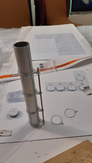
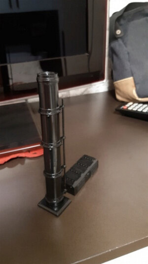
In uno dei post precedenti di questo stesso argomento ho parlato del fumel.
Per creare questo pezzo, ho usato il solito programma Rhinoceros e poi ho chiesto a un mio amico di stampare il pezzo.
Già la stampa non mi piaceva molto a causa della zigrinatura ma quello che tolse ogni dubbio è stata la deformazione dovuta al caldo (probabilmente dovuta all'esposizione al sole).
Quindi ho deciso di non usarlo e di trovare un'altra strada.
Per ridurre il peso di un elemento posto così in alto (e quindi molto influente sulla posizione del baricentro) ho cercato di utilizzare materiali leggeri.
Tutti i tentativi di utilizzare materiali plastici, ad esempio tagliando i tubi a misura, erano solo un'inutile perdita di tempo.
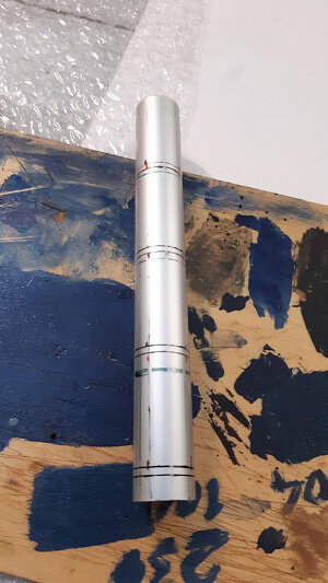
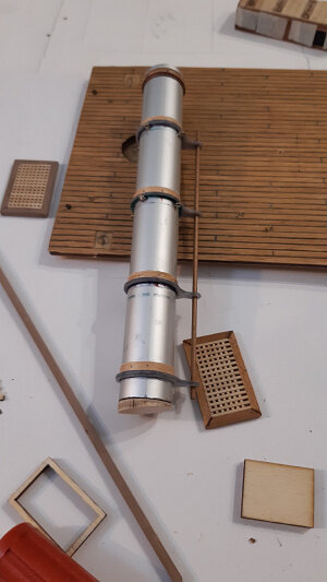
Alla fine ho utilizzato un tubo di alluminio.
Il problema principale era creare pezzi particolari.
Piuttosto che descriverli, li mostrerò in foto.
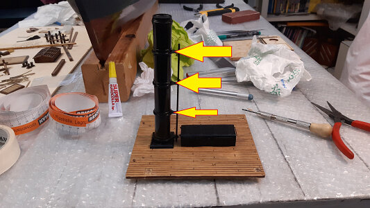
Sono quelli indicati dalle frecce nella seconda foto.Inutile dire che il risultato con la stampante 3D è stato pessimo, quindi ho adottato un metodo insolito per molti ma ormai consolidato per me.
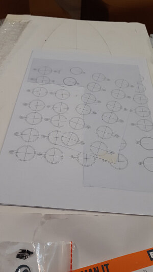
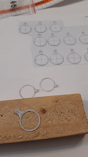
Ho disegnato il pezzo in 2d, poi l'ho incollato su sottili fogli di plastica che ho unito insieme per formare un unico pezzo da più strati.
Sono soddisfatto del risultato e consiglio questo metodo ad altri modellisti RC perché il pezzo è venuto preciso, leggero e molto resistente.
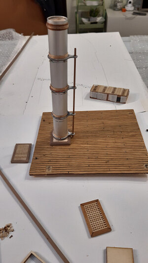
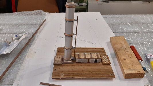
La sequenza di immagini mostra le principali fasi di montaggio e i materiali utilizzati.
Ti risparmierò i dettagli del taglio e altri passaggi ovvi.
Per dare la giusta inclinazione al fumo ho utilizzato un piedino di legno opportunamente sagomato.
Purtroppo non ho pensato di predisporre un sistema che emetta fumo.

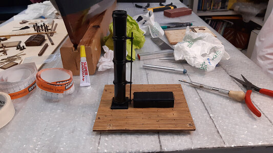
P.S. Su questo coperchio la maniglia è la struttura a forma di parallelepipedo di colore nero, ahahahahahah.


Hello everyone

In one of the previous posts of this same topic I talked about the fumel.

To create this piece, I used the usual Rhinoceros program and then had a friend of mine print the piece.
I already didn't like the print very much due to the knurling but what removed any doubts was the deformation due to the heat (probably due to exposure to the sun).
So I decided not to use it and find another path.

In order to reduce the weight of an element placed so high (and therefore very influential on the position of the center of gravity) I tried to use lightweight materials.
All attempts to use plastic materials, for example by cutting pipes to size, were just a useless waste of time.
In the end I used an aluminum tube.

The main problem was to create particular pieces. Rather than describe them, I'll show them in photos.
They are the ones indicated by the arrows in the second photo.

Needless to say, the result with the 3D printer was terrible, so I adopted a method that is unusual for many but now consolidated for me.
I drew the piece in 2d, then glued it onto thin sheets of plastic which I joined together to form a single piece from multiple layers.
I am satisfied with the result and recommend this method to other RC model makers because the piece came out precise, light and very resistant.

The sequence of images shows the main assembly phases and the materials used.
I'll spare you the details of cutting and other obvious steps.
To give the right inclination to the fumel I used a suitably shaped wooden foot.

Unfortunately I didn't think about setting up a system that emits smoke.
PS Su questo coperchio la maniglia è la struttura a forma di parallelepipedo di colore nero, ahahahahahah.


1__fumaiolo.jpg

2__fumaiolo.jpg

3__fumaiolo.jpg

4__fumaiolo.jpg

5__fumaiolo.jpg

6__fumaiolo.jpg

7__fumaiolo.jpg

8__fumaiolo.jpg

9__fumaiolo.jpg

10__fumaiolo.jpg

11__fumaiolo.jpg

12__fumaiolo.jpg

13__fumaiolo.jpg

14__fumaiolo.jpg

15__fumaiolo.jpg

16__fumaiolo.jpg

17__fumaiolo.jpg
 
Back
Top