-

Win a Free Custom Engraved Brass Coin!!!
As a way to introduce our brass coins to the community, we will raffle off a free coin during the month of August. Follow link ABOVE for instructions for entering.
-

PRE-ORDER SHIPS IN SCALE TODAY!
The beloved Ships in Scale Magazine is back and charting a new course for 2026!
Discover new skills, new techniques, and new inspirations in every issue.
NOTE THAT OUR FIRST ISSUE WILL BE JAN/FEB 2026
You are using an out of date browser. It may not display this or other websites correctly.
You should upgrade or use an alternative browser.
You should upgrade or use an alternative browser.
Thanks! Don caught that during prototyping. CAD has been corrected for the models.
When fabricating parts on my Shopbot CNC, I use 3D Tabs versus traditional tabs to hold the parts in the billets. These tabs are shaped like small triangles and are very easy to cut. In my CAD software I can define the size, location, and number of tabs. Here is a short video to demonstrate.
Awesome, Mike! Are you back from Florida?
Awesome, Mike! Are you back from Florida?
Get home tonight. Having fun posting from my iphone.
Prototype assembly continues with planking of the lower deck.
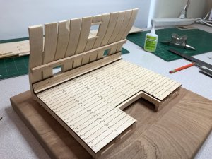
The use of laser char for the caulking appears to work well.
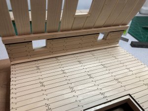
Also installed the spirketing on the inner sides of the frames up to the clamp.
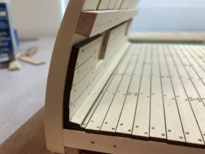
The specific edge angles on the upper clamp and waterway plank were accomplished manually using my Byrnes Disc Sander.

The use of laser char for the caulking appears to work well.

Also installed the spirketing on the inner sides of the frames up to the clamp.

The specific edge angles on the upper clamp and waterway plank were accomplished manually using my Byrnes Disc Sander.
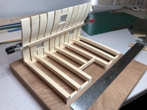
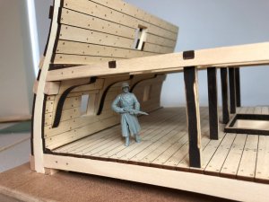
The next step was to build the prototype upper deck framework.
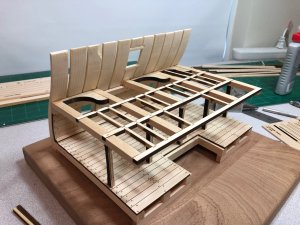
The carling notches as well as the support columns required some minor adjustments. Some of these parts were rendered for fabrication by either CNC or Laser. We will decide which when it comes time to build our final models.
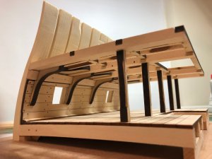
We discussed three different ways to do the support columns. Don is going to attempt to fabricate them on a lathe with capital/square tops and bottoms with round center sections. The hanging knees came out nice and tight. I used a fitment method learned while building the LSS AVS Patrick Henry on these parts.
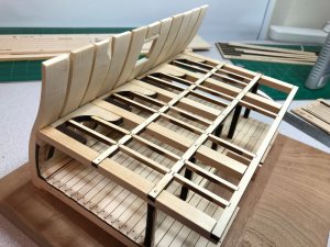
The fit of the parts continues to be very, very good. Technically, the rails should probably be notched into the lodging knees. But since this area will be covered in planking, I didn't do that for the prototype. Doc, Don and I will make that decision before we build our final models.
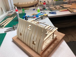
Is it starting to look like the side of a ship?

The carling notches as well as the support columns required some minor adjustments. Some of these parts were rendered for fabrication by either CNC or Laser. We will decide which when it comes time to build our final models.

We discussed three different ways to do the support columns. Don is going to attempt to fabricate them on a lathe with capital/square tops and bottoms with round center sections. The hanging knees came out nice and tight. I used a fitment method learned while building the LSS AVS Patrick Henry on these parts.

The fit of the parts continues to be very, very good. Technically, the rails should probably be notched into the lodging knees. But since this area will be covered in planking, I didn't do that for the prototype. Doc, Don and I will make that decision before we build our final models.

Is it starting to look like the side of a ship?
Looking great Mike, but out of curiosity, how did you chip that one frame? By accident handling it or did the CNC mill cause the chipping? If you're using ArtCAM to generate your g code files, you can use curved lead-in and lead-out paths that can help eliminate such chips. You can also try reversing the direction of the cut, at least I think ArtCAM has that feature.
Bob
Bob
Hi Bob. Nah.... that chip was already in the cheap piece of poplar I used for the prototype frames. Since it's "only" a prototype and since it will be covered on all sides by planking and the gunwale - I didn't care. I use ramp-in and ramp-out on my cuts as well as other techniques on my CNC. Still learning of course - but with projects like this and people like Doc and Don pushing me the learning is advancing at a very rapid rate!!!
Hi Bob. Nah.... that chip was already in the cheap piece of poplar I used for the prototype frames. Since it's "only" a prototype and since it will be covered on all sides by planking and the gunwale - I didn't care. I use ramp-in and ramp-out on my cuts as well as other techniques on my CNC. Still learning of course - but with projects like this and people like Doc and Don pushing me the learning is advancing at a very rapid rate!!!
Well, if you have any questions let me know. I had 2 shopbots when I was producing kits like the Kingfisher. I know all the tricks of CNC milling and ArtCAM which I really liked.
Bob
More prototype pictures...
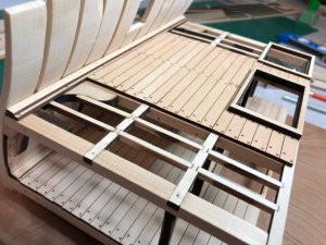
We will only partially plank the upper deck to help show off the framework.
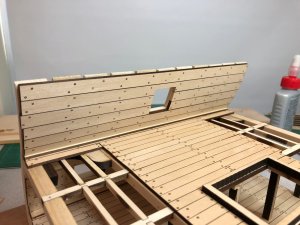
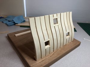
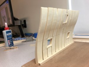
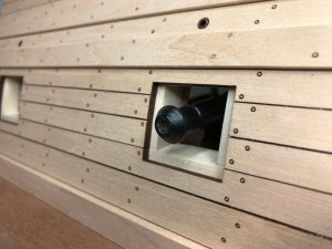
Spirketing and waterway planks installed. We realize some of the treenail alignment is off and an error with waterway placement. These will all be adjusted for the models. That is why we build a quick prototype.
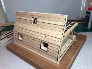
Outer planking and wales. A variety of changes will be made in this area and different woods will be used to achieve the look we want.

We will only partially plank the upper deck to help show off the framework.

Spirketing and waterway planks installed. We realize some of the treenail alignment is off and an error with waterway placement. These will all be adjusted for the models. That is why we build a quick prototype.

Outer planking and wales. A variety of changes will be made in this area and different woods will be used to achieve the look we want.
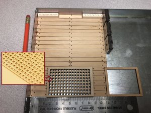
It's difficult to shoot video of CNC in action because 1) it is very loud, 2) there is usually a dust boot attached which hides the bit from view, and 3) you really shouldn't get too close to a bit spinning at 14,000 rpm. Here is a short video of when I was cutting out the shot racks and a picture of the end result. Enjoy.
Notice how the bit ramps in as it begins its cut around the perimeter. You will also notice the bit jog up and down in a couple of places as it creates
the 3D tabs used to hold the part in the billet. It's quite fast, don't sneeze or you will miss it.
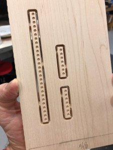
the 3D tabs used to hold the part in the billet. It's quite fast, don't sneeze or you will miss it.

What kind of bit are you using Mike and what is the diameter?
Bob
Bob
What kind of bit are you using Mike and what is the diameter?
Bob
It's a 1/16" tungsten-carbide tapered ballnose, 1/4" shank. The bit is from Onsrud. Not cheap but its the brand recommended by Shopbot.
Ok, thanks, was just wondering.
Bob
Bob
G'day Mike, Dave and Don
I'm referring to that there are only 3 versions that will be done. I'm certain that you will get a lot of orders from your fellow SOS family, if you decided to do some 'kits'. I would be one of the first to order it!
This is an exciting and a challenging task that you three are doing and I'm taking my hat off to you all.
What are the thickness and size of the planks, the beams, posts etc.? If you don't mind me asking.
The treenails effects on the planks are brilliant and so presided.
Keep up the great work, and please think about making a larger production run for your family st SOS.

Havagooday and happymodeling mated
Brilliant work my friends!
I've just found this exciting log, but there's one thing that I do not like! It would be very easy to fix, if you wanted to.
I'm referring to that there are only 3 versions that will be done. I'm certain that you will get a lot of orders from your fellow SOS family, if you decided to do some 'kits'. I would be one of the first to order it!
This is an exciting and a challenging task that you three are doing and I'm taking my hat off to you all.
What are the thickness and size of the planks, the beams, posts etc.? If you don't mind me asking.
The treenails effects on the planks are brilliant and so presided.
Keep up the great work, and please think about making a larger production run for your family st SOS.
Havagooday and happymodeling mated
Hi Greg. We are very, very appreciative of your compliments on a project we have only just begun.
The plans for this kit are copyrighted. We will not be producing kits. We are scratch building only 3 examples. The Lumberyard has a kit of this model if you would like to purchase one.
Regarding the work Dave, Don, and I do... this is only the tip of the iceberg. You can expect many great things in the future.
Thanks again.
Thanks to all for stopping in and watching our little project. We are making headway and finding a few bumps along the way, to date all have been easy fixes so frustration levels are still good.
As Doc is milling the final product Mike and I are building prototypes. I know this may seem unfair as Doc is having all the fun, but we are happy with the arrangement and are still all talking to each other.
The first two cannon/carriage prototypes have been completed and other than two sets of old eyes not catching the four different thicknesses of wood required(Thanks Doc for catching that) everything went together fine. Doc has suggested we both go for eye exams at which point I said I just had one and it was just a matter of remembering where I left my glasses. To date I don't believe Mike has any sort of excuse.
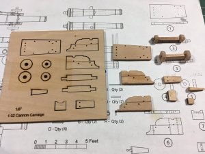
Picture of billet and pieces. With Mike's method of laser cutting there are no tabs to cut, he puts tape on the back and the pieces literally fall off when the tape is removed
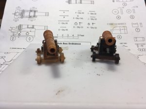
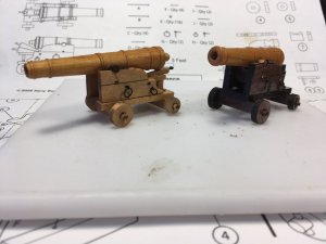
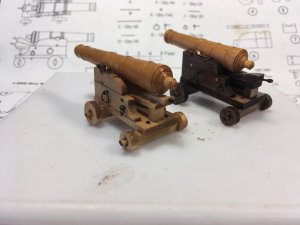
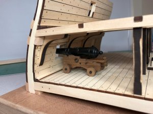
And the completed prototypes, final barrels will be made from 1/2" brass and the carriages from cherry
Thanks for looking in and don't go too far, more to come
As Doc is milling the final product Mike and I are building prototypes. I know this may seem unfair as Doc is having all the fun, but we are happy with the arrangement and are still all talking to each other.
The first two cannon/carriage prototypes have been completed and other than two sets of old eyes not catching the four different thicknesses of wood required(Thanks Doc for catching that) everything went together fine. Doc has suggested we both go for eye exams at which point I said I just had one and it was just a matter of remembering where I left my glasses. To date I don't believe Mike has any sort of excuse.

Picture of billet and pieces. With Mike's method of laser cutting there are no tabs to cut, he puts tape on the back and the pieces literally fall off when the tape is removed


And the completed prototypes, final barrels will be made from 1/2" brass and the carriages from cherry
Thanks for looking in and don't go too far, more to come


