17th Century Battle Station

Superb job on the prototypes, Don. I really love the style of the carriages, and we can thank Jeff Staudt for his excellent work on the plans. The final wood for the carriages and inboard bulwark planking may be swiss pear rather than cherry and the trucks will be boxwood. Either way they will look great if they're half as good as your prototypes, Don!

And your right....milling the timbers IS having all the fun!;)
 
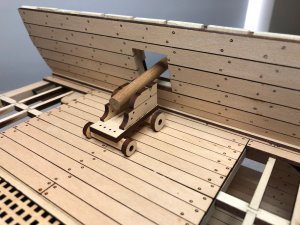
With Don prototyping the cannon up in Canada and me building the basic structure, we became concerned about fit of the cannon in the gunports. We took two different approaches. There are two different size cannon, one for the upper deck and another for the lower deck. Don measured the vertical distance from his bench to the center of the barrel for each cannon. His result was 32mm and 28mm. I repeated those measurements on the model from the deck to the center of the gunport. To my amazement, I arrived at 32mm and 28mm. Still not convinced I built a quick mock up of the upper deck cannon and threw it up there. Looks about right..... moving on.

IMG_0389.JPG
A couple coats of poly and this cannon might look as good as Don's prototype??
 
The carriages for the upper and lower deck guns are identical. Although the breech is the same, the upper deck gun is considerably shorter then the lower deck guns. Plus, it is fitted with two quoins! I've not seen that before and I assume it was used to allow the gun to fire "down" at the hull of the enemy vessel in a broadside.
 
It is a little hard to explain using Mike's prototype as it is missing the stand or bed at the back of the carriage. With the shorter barrel the back end of it rests on the bed, the one Mike left off, much further forward in the carriage causing the barrel to sit at a much higher angle. So two quoins would be required on the bed, the one Mike neglected to install, to level the barrel. With the longer barrel resting further back on the bed, have I mentioned Mike refused to add this, it sits at a much lower angle thus needing only one quoin.
 
Don you're right, of course, but it's still a little strange. Why not simply scale down the carriage for the shorter gun? On ships that carry varying sized cannons - 9 pounders, 12 pounders, 24 pounders - the carriages are a different size for each type of gun and they use one quoin to a customer! ;)
 
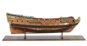
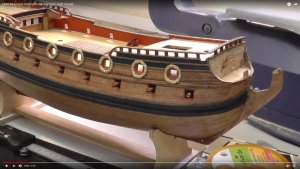
In doing some internet research, I found a contemporary model of the HMS Mordaunt, 1681. She looks a lot like our Battle Station. I also found a You Tube video of someone modeling the Mordaunt. Here's a screen shot. Looks very much like our station! I say we name our model for the Mordaunt17th2.jpgmordaunt 1681.jpg
 
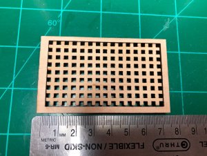
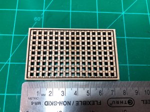
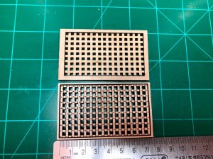
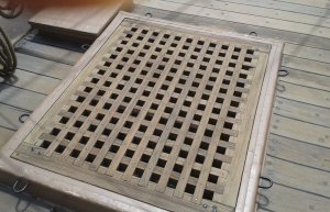
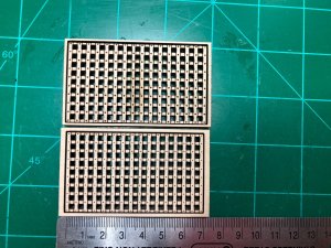
As prototype development of our HMS Mordaunt cross section continues, Don and I turned our attention back to the hatch gratings. It was obvious the grates from the original plans were simplified. So we went back to the drawing board and ended up doing a combination of both laser etching and laser cutting through 4 prototypes to get to where we are now.

IMG_0416.JPG
This was the prototype from the original Staudt plans. Don and others found this to be unacceptable.

IMG_0417.JPG
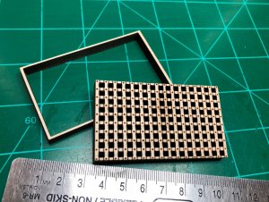
This is prototype 4. The holes in the grate are exactly 2.75 scale inches across as referenced in Mondfeld's book. The treenails are smaller etched versions of how we did the planking.

IMG_0418.JPG
Visually the added detail makes a big difference.

IMG_0419.JPG
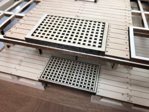
We will give the same treatment to the upper hatch as well.

IMG_0420.JPG
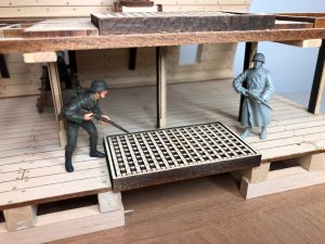
The grate is removable from the combing. This will allow Doc to choose two different woods to render these parts in the final model.

IMG_0421.JPG
Don is still not satisfied and wants to add rope lift handles to the grates. We needed to determine about how many men it would take to lift the grate. I placed a couple 1:35 scale WWII soldiers into the model to see. Keeping in mind the model is 1:32 scale so the sailors would actually be slightly larger. We estimate it would require 4 - 6 men to lift the grates. We can't find any references to handles so Don is just going to see what he can come up with. We would appreciate any suggestions or feedback.
 
Hallo Mike,
Your gratings are looking good, but it is maybe here too much photo etching, when it is allowed to say. Due to the fact, that the original beams are only appr. 10 cm thick, the used nails, two per connection point, are much smaller, so more or less realy not visible in this scale. And one additional remark, all the beams of one grating would have the same continuous width. It looks a little bit, that on the long side the outer beam has a smaller width than the others. The frame in which the grating lays has a bigger width, more or less double width of one beam of the grating, like on your first attempt.
To your question how they did it to open a grating.....i never saw a lift handle at a grating. It is relatively easy to knot a rope through the openings of the grating, the bigger ones were opened with using a yard like a lifting crane and the use of fixed and running rigging, f.e. also to lift a boat from the deck.
For preparation of heavy weather they had to close the gratings, that no water on the deck can come into the ship
 
Thank you very much Uwe, that helps us a lot!!! Our beams are already less than 10 scale cm wide. Here is what i will do today:

- Double check that all beams are the same thickness
- Increase the size of the combing frame to larger width
- Make the nails much, much smaller

We also will not add lifting handles since you explained how they would have lifted the grates in real life. Thanks again!!!
 
Hi Uwe and others. Our laser is able to etch to a very fine level of detail. Even if the nails only come out to be tiny specs we want to try it. Before I do the work in CAD, would like to hear your thoughts on which way is most accurate. Uwe said there would be two connections per point. In the picture below, we have made the nails down to 12% size of original that would be 4mm scale diameter with 2 nails per connection. We also show a nail at 50% size and the originals. Thoughts as we can find no pictures of this?

Thanks


IMG_0441.JPG
 
Last edited:
Hallo again,
I just tried to google some photos but can not find anything good enough than on pinterest, which I can not copy, but you can make a search
Try and google "HMS Victory" + hatch grating" than you can find some good photos of the grating on the original HMS Victory.
There they have these two nails used, which seems to be similar with your try. With the laser you will come to the problem, that the laser is producing by himself a thickness of dark area, so that the "nail" will be very small, but realy visible after laser etching will be the dark area and not the wooden dott in the middle.
BTW: I also found some gratings with only one nail per connection, but from the stability point of view a connection with two nails can not move to a rhomb, it will stay rectangular....... sorry for this wrong info before
maybe it is the best you realy try the versions of nailing on one wood to see the result.......
 
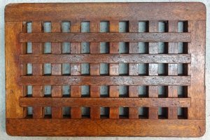
I've seen photos of the grating held together with 2 diagonally placed nails, like Victory, single nails at each juncture point in the center of the joint, and single nails placed high then low at the juncture points, alternating. Of course I have no idea what was done in the 17th century! I tend to vote for single, small nails in the center of each joint.grate2.jpggrate3.jpg
 
Thanks everyone for all the input. It seems there is a certain amount of leeway on how these grates can be done. Don and I worked on this all morning and came up with what we have decided is the final version. Take a look.

IMG_0445.JPG
Prototype 4 is on the top. Prototype 5 (Final) is on bottom. We have made the outer frame thicker and the nail heads are exactly 0.25"/6.35mm scale diameter. The vent holes are slightly smaller as well. We might sand a beveled curved edge into the frame when we build the model - will decide that later. The grating is removable as before.
 
Mike: Have you and Don considered making the outer frames the same size as the plans call for? Since I plan for the grating to be boxwood and the frames rosewood the wider outside framing will provide a more dramatic color contrast. I do like the nails and the size of the vent holes.
 
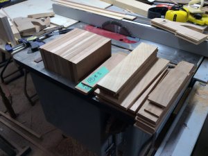
The production phase of this project began today. I cut out the billets for all the cherry parts including the frames, deck beams and framing, knees, carlings and ledges. I also bought some ebony cut-offs so depending upon what my source sends me, we may have enony fpre the wale, black strake and the 2 black sheer strakes. Icherrybillets.JPGt's a lot of wood, but it is the framing for 3 models!
 
G'day Doc
Its always fascinate me when I get all the timber for any job, and see how much there is and how quick it goes down. My wife always ask me 'did you order too much?' But it's generally correct.
I would also assume that there are more wastage using CNC than cutting out each by hand tools etc. But the time and accuracy is worth it.
Havagooday
Greg
 
Back
Top