17th Century Frigate 1:64 scale Plank on Bulkhead

Joined
May 9, 2024
Messages
314
Points
158

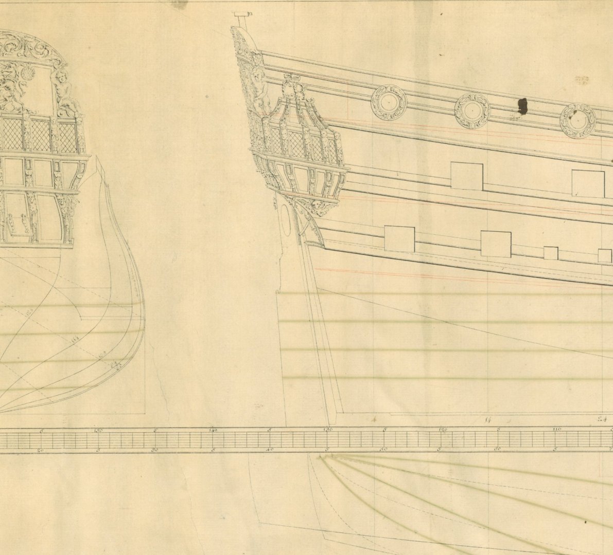
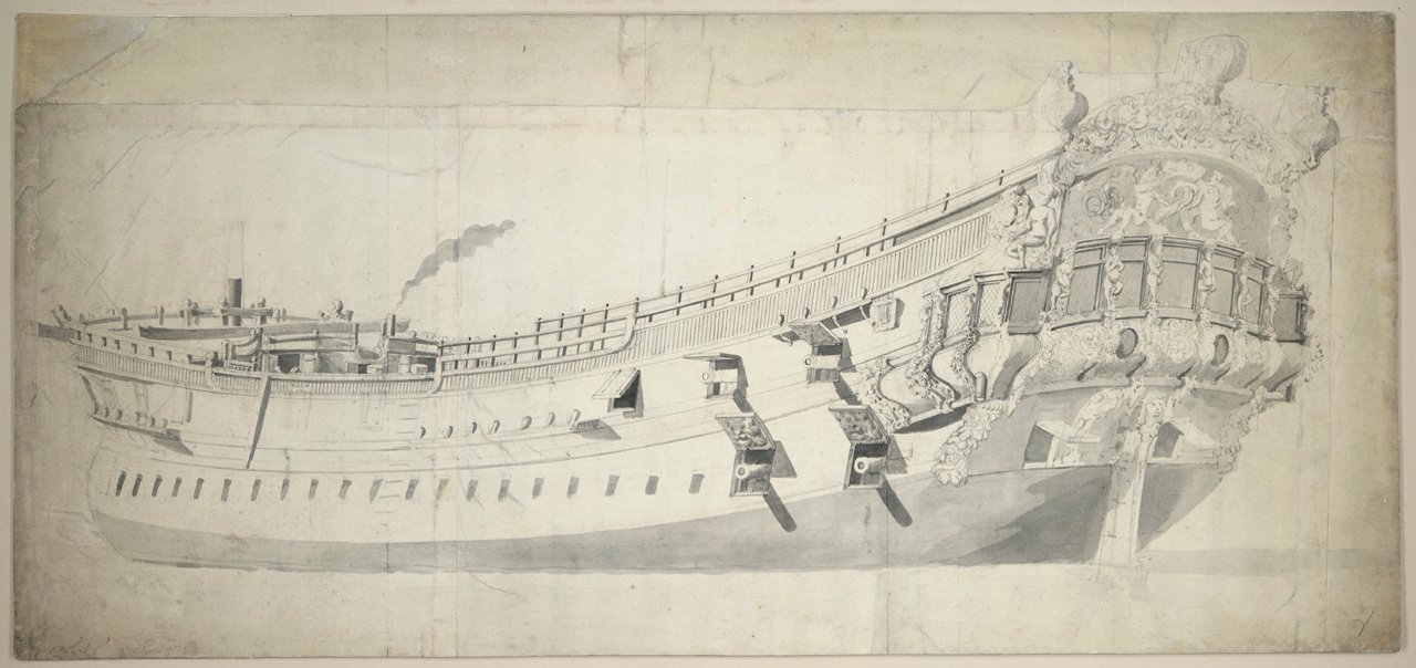
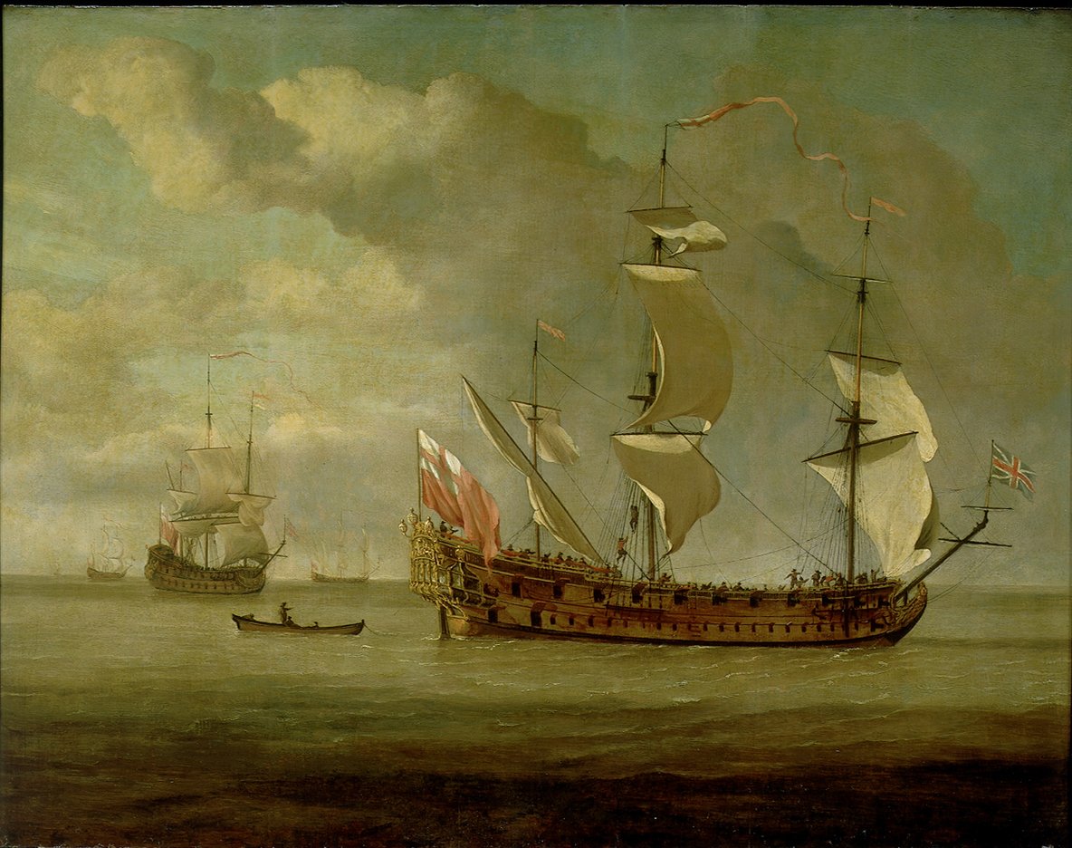
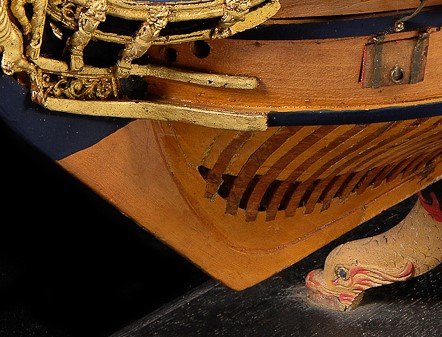
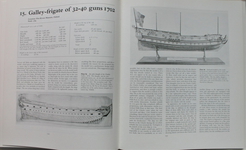
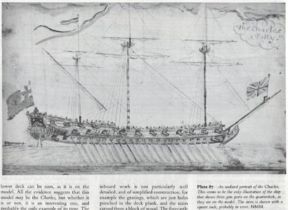
This is a build log of a 17th century British galley frigate that I built for a client a couple years ago, but I thought some members might find it interesting. It is based mainly on a RMG drawing of the Charles Galley built at Woolwich by Phineas Pett in 1676. The model has slight modifications, including one less gun port on each side of the QD and that the side be planked to the sheer rails. Drawings by Van De Velde the Elder show what may be the frames at the area of the top timbers with fillers between frames but no horizontal planking, or this may be vertical covering planks. As it was likely painted blue in any case, it will not be glaring in the final appearance. Both a sketch and a later painting (1677) of her under sail by VDV show no wreaths below the QD which is an anomaly for that time. Information from Richard Endsor's book The Master Shipwrights Secrets including the Charles Galley and a smaller ship, the James Galley are also being consulted extensively. The contemporary contract for the James Galley from the National Archives in Kew is turning out to be a big help as well, albeit with scantlings that are slightly smaller in some cases than would have been appropriate for the Charles Galley. Measuring items such as the keel on the contemporary drawing is confirming this supposition. In addition, photos of a contemporary model of an unnamed royal yacht of 1702 have striking similarities and will be used for such items as gratings, bitts, etc. Lastly, books by Lavery, Goodwin and others are being studied for a number of items. The model will be a POB and will not be rigged. I intend to give a try at the carvings using clay. Failing success in these, I will go back to using wood and my trusty set of chisels from Mihail Kirsanov.

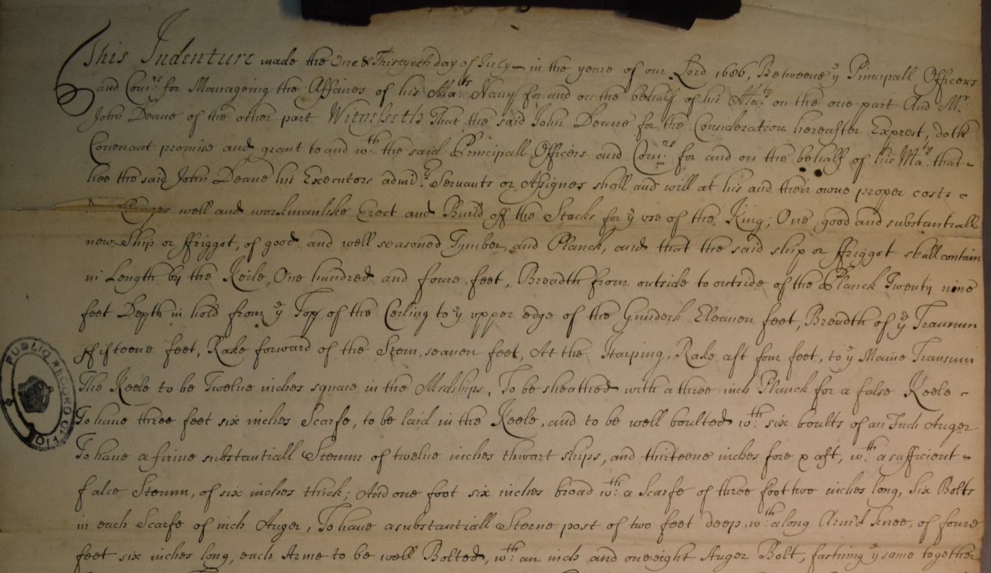
Note that the topic title should have the word Friggot. This is not a misspelling but rather the spelling used in the contract. Transcribing the contract took a few days even though the scribes had handwriting that could be deciphered more easily than others that I have transcribed in in the past. Still, there were some words that had me baffled but a friend that has studied numerous contracts and studying the paleography tutorial on the National Archives, Kew web site was a huge help.

The below is a portion of the transcription and the original contract. These can be immensely helpful in sizing various things for any build, scratch or kit. Note that the spelling, grammar, capitalizing, punctuation &c. are as in the contract. For those who have not tried to read one of these contracts, it is a fun, and often frustrating, experience.

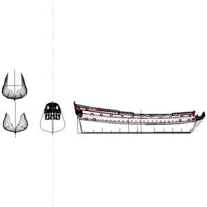
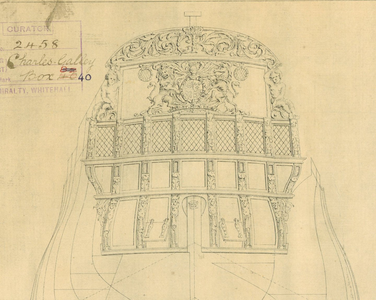
The drawing below from RMG is shown in part, as well as one of the VDV drawings.

Allan

This Indenture made the One and Thirtyeth Day of July in the year of our Lord 1686 Betweene ye Principall Officers and Com.rs for Managing the Affaires of his Matys Navy for and on behalf of His Majesty on the one part and Mr. John Deane of the other part Witnesseth that the said John Deane for the Considerations hereafter Exprest, doth covenant, promise and grant to and with your principall officers and commissioners for and behalf of His Majesty that hee, the said John Deane, his executors , admins servants or assigns, shall and will at his and their own proper costs and charges well and workmanlike will erect and build off the stocks for the use of the King, one substantial new Ship or Friggot of good and well seasoned Tymber and Planck and that the said Ship shall contain in Length by the keel one hundred and four feet, Breadth from outside to outside of the Planck Twenty nine feet, depth with hold from ye Top of the Ceiling to ye upper edge of the Gundeck eleavon feet, Breadth of ye transom fifteen feet, Rake forward of the Stem, seavon feet, At the Harping, Rake aft four feet, to ye Maine Transome The Keele to be Twelve inches square in the Mid Ships, To be sheathed with a three inch Planck for a false Keel ~ To have three feet six inches Scarfs, to be laid in the Keele, and to be well boulted with six boults of an inch auger To have a firme substantiall Stemme of twelve inches thwart ships, and thirteene inches fore and aft, wth a sufficient False Stem, of six inches thick, And one foot six inches broad wth a Scarfe of three feet two inches long, six bolts in each Scarfe of inch Auger, To have substantiall Sterne post of two feet deep wth a long Armed Knee, of foure feet six inches long, each Arme to be well Bolted, wth an inch and one eight Auger Bolt, fastening ye same together

Original
259831033_Contract-portionofpage1.thumb.jpg.fff9b2a2f5470b85d7c7c26ac36a8e03.jpg

673378521_J6899partial.thumb.jpg.a4a87d9af2ca8ffaa208ec6db91db546.jpg
pz7276.jpg.910d3e71a446d0c8e5c16f34a0f4d474.jpg
1752143455_PaintingbyVDV.jpg.998286df92b2a3fd215e29ad9d332193.jpg
Allan
 
Last edited:
.​

Hi Allan,

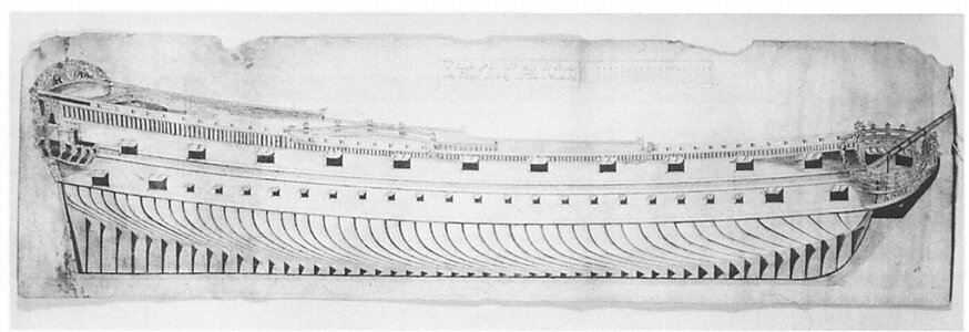
Did you also use this clearly 17th century plan below? On it are also those mysterious vertical decorations(?). I was even going to analyse the ship's lines for a design concept, however, the poor quality of my copy of this draught and the lack of contours of the entire upperworks above the wale stops me from doing so. Perhaps you have a better copy of this drawing?


English galley-frigate.jpg

.​
 
Hi Waldemar
I used the Charles Galley lines and body plan that was available on line at RMG at the time. I just checked and it is no longer available on line. The below, with some lines I drew on it is what I worked with along with drawings by Richard Endsor. I had it as a JPG and inserted it into my CAD program and then traced all the lines. Below is the traced copy that I drew and a pdf of the contemporary plans.
Allan
Profile and body plan.PNG
 

Attachments

  • Charles Galley Lines.PDF
    16.2 MB · Views: 91
Last edited:
The more I studied the 17th century ships, the more differences I found compared to the 18th and early 19th century. Starting with the keel, the rabbet starts at the top of the keel as shown here as the frames sat directly on top of the keel without a mortice cut into the floors and first futtocks' chocks. As this is to be a POB, and will be totally planked it is not so critical, but I followed this style in making the keel regardless. I found it easy to make the keel with two chamfered pieces, one top of the other.
1477445122_Keelendphoto.jpg.1ec0fa4ac2b51e10fa70e7f9994de8e3.jpg

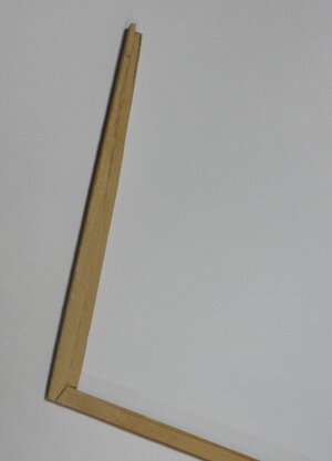
The boxing joint also is a bit different than what I am used to for later eras. This alternative design is shown on drawings of Lenox, Mordaunt, Charles Galley, and James Galley by Richard Endsor. These are based on the joint shown in a drawing by William Sutherland in Shipbuilding Unvail'd, 1711, page 26. I did forego making the joint as a tabled scarph as the tabling cannot be seen and for the model, the boxing joint without the tabling is still incredibly strong. In the first photo of the boxing joint below the drawings, the false keel has not yet been made and assembled in place on the bottom of the keel. There is a good bit of information on various boxing joints in Anderson's book Navy Board Ship Models. Goodwin shows several styles n the Construction and Fitting of the English Man of War but does not include the design shown in Sutherland and gives no dates for the various designs he does show. As with many things in our hobby, I have had to make what I hope is a well educated guess as to the design that would be appropriate for this ship. Note that I cannot find any models contemporary to the Charles Galley that show any type of boxing joint. One example is the last photo below. Note that the keel itself tapers in width fore and aft from midships as does the knee of the head and stern post.
310304566_BoxingJoint.JPG.e39688c5e059a39b427826688f8cf0cd.JPG

595095943_Boxingjointonkeel.JPG.04c262db47c3ed6c8d921d1b4ffd02a8.JPG
521546254_Bowphoto2.jpg.e2deba40b08e8473e43d7b6ca3813ed9.jpg
 
.​

Thanks. So one is left to believe that these reconstruction plans, removed from the RMG website, were reliably made, especially as they were most likely by a competent Navy Board ship designer (he is otherwise known to have taken a liking to drawing reconstructions of 17th century ships).

.​
 
So one is left to believe that these reconstruction plans, removed from the RMG website, were reliably made, especially as they were most likely by a competent Navy Board ship designer (he is otherwise known to have taken a liking to drawing reconstructions of 17th century ships).

Waldemar,
Sorry, but I am not sure what you mean by "he". Are you speaking of the draftsman or the naval architect? Either way, I surely hope whoever did these plans was competent and got things right.

Barring better contemporary information, I think the drawing is the most reliable available. I emailed Richard Endsor about this drawing when I started re-drawing the model and he indicated that there was no better information available than the VdV work and these plans based on his own research when writing the Master Shipwright's Secrets which included his own renditions of the Charles Galley.

Allan
 
Hi Waldemar
I am sorry but I had never seen the drawing you posted before, but would love to find it. Do you have a catalog number or other identifier where your drawing is held such as RMG or elsewhere?

If you mean the Charles Galley plan, please feel free to PM me your email address and I can send you the high resolution (19.6 MB) drawing to your email.

Allan
 
.​

I myself received the drawing shown earlier from my friend Martes, who is constantly dropping off such fantastic and previously unknown material to me, as a kind of orphan without provenance or reference numbers. I have already sent a question to him about it.

As far as the plan from RMG is concerned, yes, I will ask for a good quality copy, with the intention also perhaps of carrying out a conceptual analysis of this design. I'll send you my email address right away, however, for sending large files perhaps a more convenient method is to use the built-in message system on the SoS forum (user "-Waldemar-"; not "Waldemar"!) or the MSW forum of still greater capacity in this respect (user "Waldemar").

.​
 
.​

Many thanks, Martes. Now that you've pointed out the source, primary (archives) and secondary (reproduction), I've made another scan of another illustration from the same chapter on Charles Galley. Perhaps useful for someone who doesn't have the book or the means to purchase a reproduction from the archives.


Charles Galley 1676.jpg

.​
 
Hi Martes
Yes I have done that in the past. Their prices are a bit high, but considering the wealth of information that they make available, to me, it is worth the investment.


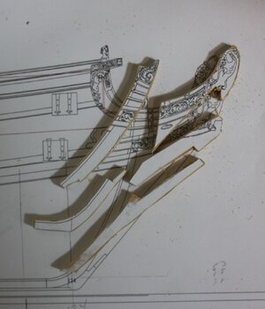
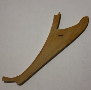
As the client wanted a fully planked model, we agreed to plank on bulkhead which simplified the build. The deadwood aft and apron and stem forward were made of single pieces. The knee if the head was made of individual pieces as it is visible. The first picture is the stern post attached to the keel. From what I could find the construction was different than was done in later years. The rabbet runs all the way to the post where as it stopped short of the post in later years..
Stern post joint on keel.JPGStem and knee of the head pieces.JPG
Stem and knee of the head.JPG
It cannot be seen in these photos but the stern post tapers from the top to the bottom when looking at it from aft. From the side it tapers from the bottom to the top. Similarly the knee of the head tapers from the stem to the seat of the figure head fore and aft and the stem tapers from the top down to the keel as the keel is narrower at the bow and stern than at midships.
 
Last edited:
Frames/bulkheads) were drawn based on the station lines, for the most part. Several are not exactly on the station lines to account for the openings of gun ports that will be open and will create the sides of the ports. Unlike POF, this was a relatively easy endeavor but a sufficient number of bulkheads are needed to give enough landings for the hull planking. Some filler pieces were used between the bulkheads for strength and additional landing surface for the planking. The bulkheads are set up to act as deck beams as well, but as this was to be totally planked, only the decks that would be visible were cut into the bulkheads as seen on the example below. I like to print drawings of parts to be cut out on label paper and then stick them on to the wood that is used for the individual pieces For the bulkheads on this model I used birch veneer plywood. For me, label paper is far easier to use than gluing regular paper which can tend to stretch and wrinkle at times when wet with glue. Even a glue stick is troublesome compared to using label paper.

Aircraft plywood would be a far better choice, but it was costly ($250 for a 4 foot X 4 foot sheet -1/4" thick, including freight a couple years ago).
NB: Unlike the majority of other contemporary drawings I have studied over the years, the station lines of the Charles Galley are all numbered, from 4 aft to 124 forward. No letters are used forward or bracketed station numbers and letters in the area of the dead flat are used on the original plans.

Note the thickness of the top timbers. Lacking better information I used the scantlings from the 1719 Establishment. The contract I have for the Mary Galley addresses some of the frame timber dimensions, but not the top of the top timbers. Because other dimensions are very close to those for a thirty gun ship in the Establishment scantlings I used those and in this case it is 2.5". This dimension increased to 4" for ships built to the 1745 Establishment scantlings. Examples of the drawings and a couple pieces are below. I put the caliper in the photo at one inch to give an idea of scale.

Allan


236451484_Framedrawings.JPG.2558cfa133a4bddaba3c2ce39f841ac9.JPG

952024168_Bulkheadexamples.thumb.JPG.342379bcd73b6f4e9e04029a0a079f1d.JPG
 
Last edited:
While I enjoy plank on frame construction more than POB, POB does go faster and delivery was an issue. As no internals will be viewable, POB is definitely a nice alternative to POF. In the photos below the QD and FC bulkheads are yet to receive decoration and moldings and only set in place for now without glue so a couple filler pieces between bulkheads are not yet in place. Filler pieces are in place between the other bulkheads to give some rigidity and the entire unit has to be faired once the two loose bulkheads are complete and fixed in place. At this point there was work yet to be done in fairing the deck line as well as the outside of the hull, but not too much.

The bulkheads are not all evenly spaced. Some of the bulkheads are on the station lines which were very easy to draw and make. Others are offset to account for the gun ports that will be left open and the QD and FC bulkheads which do not sit on a station line so a bit of lofting had to be done in each case. At this scale, the top timbers were weak but once the filler pieces were glued in place, this problem went away and stood up well to the preliminary rough sanding, even with a vibrating mouse.


267122040_Deadwoodaftkeelandstem.thumb.JPG.c3e593b18e61a7746221dd0cfb4c3dff.JPG


1222118237_Partiallyframed.thumb.JPG.6cf8c673819da34a916857c1a13f9a58.JPG216836289_Partiallyframedstarboardside.thumb.JPG.97e70158689cdb4211d6b7d60e9b9bdd.JPG
 
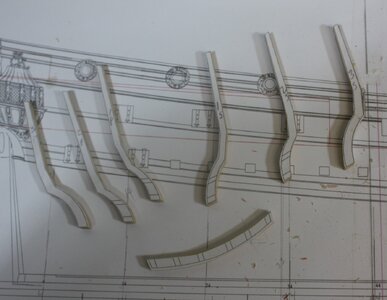
Stern timbers were pretty standard pieces. Again, I printed the pieces onto label paper. Each timber is slightly different than the others in shape and size.
Stern timbers and wing transom.JPG


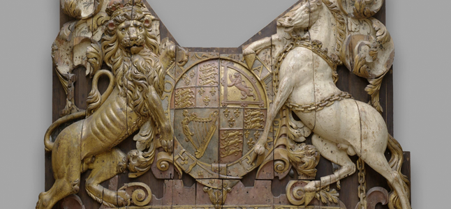
While the scale is decidedly small, carvings still need to be done with as much precision as possible. The carving is from the Rijksmuseum for the Royal Charles, and is a close match for the drawing of the stern carving on the Charles Galley. I understood the motif would be normally the same for a given monarch and this appears to confirm it.

1719052453903.png
1719052483561.png


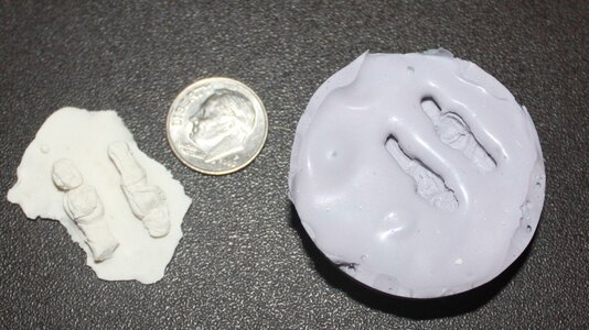
Decorations can be carved or made from clay. In the interest of time I went with clay. After seeing some posts by famous "Doris" on making clay figures I saw no reason not to give it a try. Where multiple pieces were needed I made the first port and starboard version, them a silicone mold and cast resin pieces. I see that there were videos posted here at SoS of her work 6 years ago. They are no longer available but if anyone knows how to get these and can share a link that would be great.
Stern decoartion mold.JPG


Allan
 
I redrew the stern by tracing the original on my CAD program and it was then used as a sort of template when laying out the pieces of clay to form the various figures.
Stern AAA.PNG
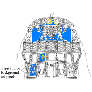
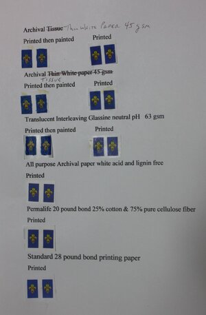
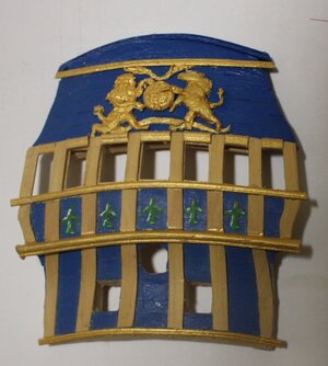
Some of the decorations are painted. Initially I hand painted the fleurs-de-lis but was not happy with the results. I then "painted" them via CAD then printed them on various types of paper. Once printed I hand painted to soften the edges and try to yield more of a hand painted look. The initial hand painted version can be seen below followed by the paper version in the last photo below.


Paint samples A.JPG

I built the stern off of the ship for a change and it worked out very well. I may never do it that way again, but it was easier working the stern laying somewhat flat. The first part of the assembly is below.

Stern B.JPG
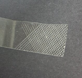
The stern and quarter gallery light glass pieces were made of scrap plastic sheeting. I score the individual panes with a scalpel to create the wire pattern.
Stern light material.JPG
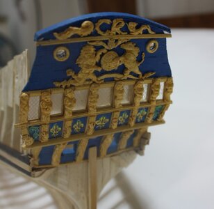
After making and assembling all the carvings:
Stern April 30 2021.JPG
 
Last edited:
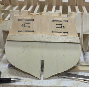
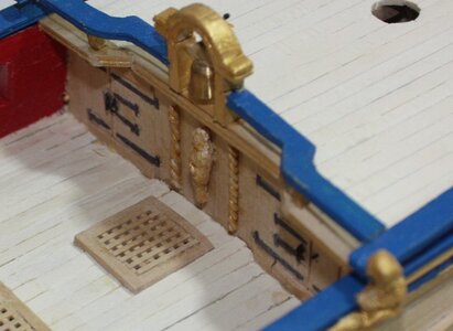
This is a bit out of order. The QD and Forecastle bulkheads had two doors with small panels that could be opened for small arms fire against boarders. An interesting thing is that there were were ladders from the upper deck up to the quarter deck but there are none to the forecastle. To get up to the forecastle require the sailors to get up onto the planksheer then up onto the forecastle. The shrouds were there for to grab by hand while getting up to the forecastle.
QD bulkhead partially complete.JPG
No ladders from upper deck to forecastle.JPG
 
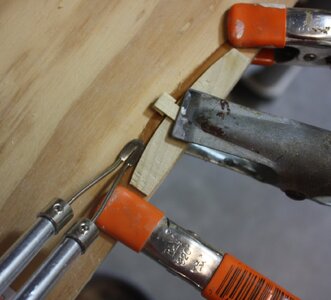
Hull planking was done using edge bending. The hull was lined off first then a strake of planking was tapered in breadth to match the mark. Each plank was then soaked and bent around a form to match the line of a spiled plank. I used to use a flat blade on a soldering iron as in the photo below but have since gone to a hot air gun, the temperature of which is easier to control and is more efficient to use.
Pre-edge bending a plank.JPG

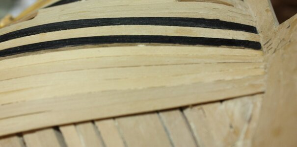
While the planks were tapered in breadth so they could all land at the rabbet, one of the things that is often missed is the tapering of the thickness of the wales. The rabbet varies in its angle from something of a vee shape to an "L" shape aft, but the depth is somewhat constant fore and aft. If the wales are left standing proud of the surrounding planking it cannot be properly seated in the rabbet. In the case of this 17th century vessel the wales were less broad than in later years, with the main and channel wales being in two pairs of strakes.
IMG_6692.JPG
IMG_6691.JPG
 
Back
Top