1930 Bentley Blower by Aifix 1/12 build log [COMPLETED BUILD]

Looking fine!!!

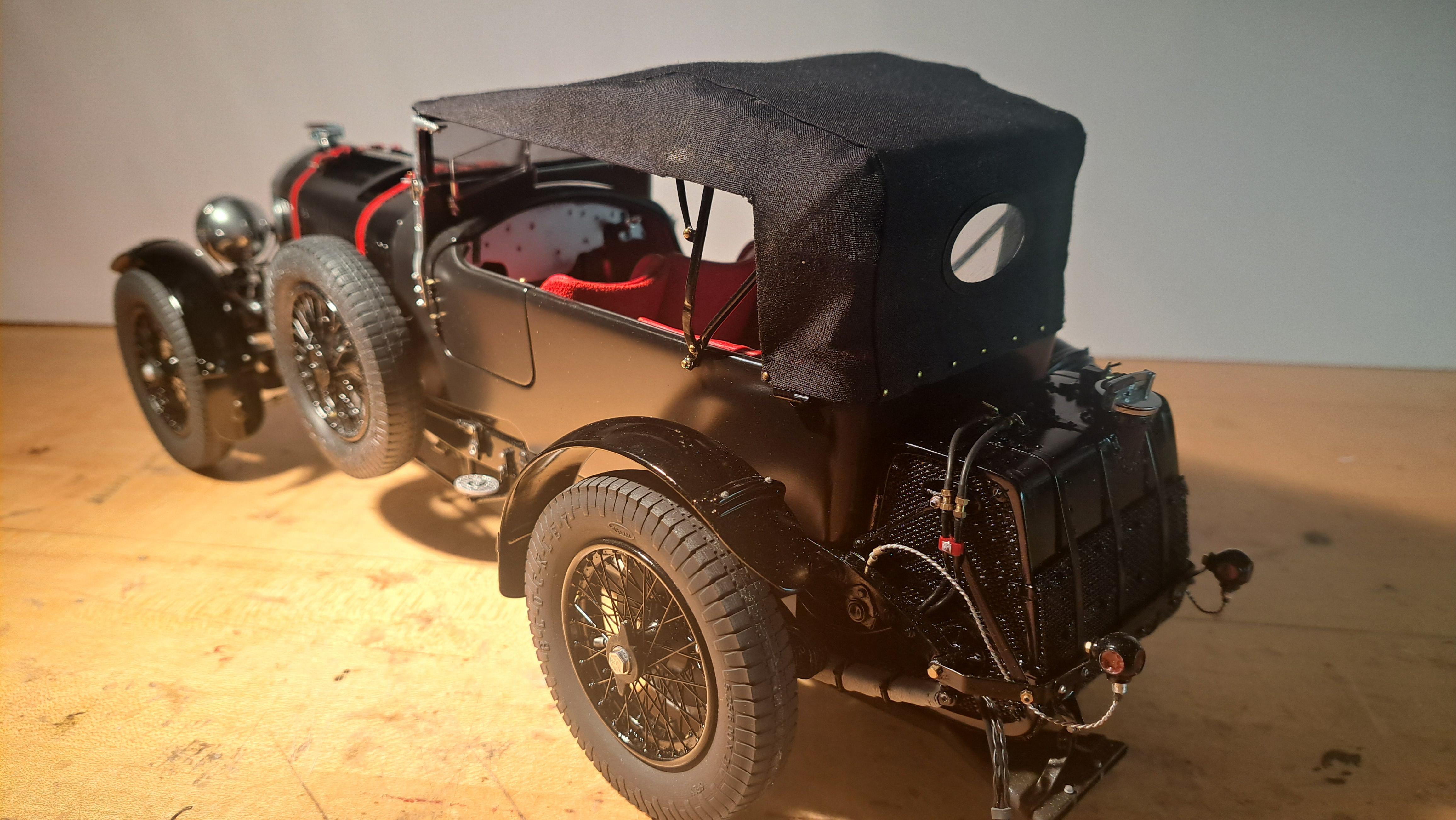
" I still need to figure out how l will attach it to the front bar and to the rear."

Francois, I worked with my upholsterer when he did the top for my '31 Ford Roadster as it was his first street rod top. What we did was to form a tapered header mad out of a hard wood, maple as I recall, for the front, attached it to the top frame. The top Haartz fabric was then stapled to the frame then a strip of thin welting added to hide the staples. For the rear, he used top colored snaps with the male part screwed into the steel body with hard wood backing for reinforcing. The female snaps were installed in the material. After it was done, we did agree that those female snaps would have looked better if there had been a skirt covering them but they are not obtrusive. 15 years later, that top still looks as good as new.

While I suspect that this will not be your final solution, it will give you a couple ideas an how to proceed.
 
Thanks foe the info Dave. Having done several soft top installation on real car, I know the mecanics of it. For the scale model, It's more like do I use magnets, mini nails, glue? I'll figure out something. Thanks again everyone for following my adventure, this built has been a real blast and very formative for me, I hope it has been the same for you.
 
I made the rear window for the top. I printed a window surround and also cut a plastic window.


Then I drilled a 0.6mm dia hole in the center of the foldable frame pivot screws and inserted a small brass nail to simulate a snap to hold down the sides of the soft top.


And finally I drilled small holes on the end of the tub and inserted brass nails thru the soft top to hold it in place. Now all that is left to do is to glue the front of the top to the header bar.


I found a drawing of a bentley with the top up and it's a bit different from what I made.

Screenshot_20240528_164705_Photos.jpg.9bd82a518565d30c31e932fdd1247f42.jpg


Since I couldn't find any pictures showing my ref car with the top up, I decided to modify my top to look a bit more like the drawing. As a bonus, it will better show the foldable top frame.

20240528_164306.jpg.46629ba1423befc7957ef36afaaf14ac.jpg
 
Ok, break's over, time to finish this thing. I completed the 3d model of the dashboard. Nick, from Britmodeler, gave me his gauge facia art work. I'll send him some 3d files of a few parts I'm pretty sure he did not model yet in exchange. So that's one problem solved. The next hurdle is the dash aluminium face plate. It has an engine turning pattern on it. I came up with a (possible) solution to create the pattern without the aid of sophisticated equipement such as a milling machine or cnc. I designed a multi stage jig that should help me do the pattern manually. More on that later on.

Here is the completed 3d model of the dashboard.

Capturedcran2024-06-07215124.jpg.b8269cc9f532803fe2696ec6d5f65789.jpg


A real dashboard


I also made the last of the 3 filler spouts.


Ok, dashboard update time.

I've read alot about engine turning and one thing I've learned is that at this scale, it's call jewelling or 'perlage' in french and is a finish found on high end watches. Engine turning for much larger applications. Both methods are identical except jewelling will requier a very small tool. Here's what jewelling looks like.

greubel-forsey-perlage.jpg.25f441ef1151133a759b22f78e80117f.jpg


My idea of a multi stage jig didn't work, it was too complicated. The idea was to have a plate that held an aluminium sheet in place while also locating the different drilling jig, 4 in all (thus the multi stage). Each drill jig had a different hole pattern that guided the jewelling tool. Once all 4 jig used, I would have the jewelling pattern. The main problem was that the holes could only receive a certain diameter tool. A change in diameter meant 4 new jig to reprint. It was also difficult to see what I was doing.

Here's the jig


Instead, I designed a simple 2 part tooling. A lower plate that has .09" dia pins spaced at .72" (8×.09) intervals and a upper plate that has a .09" diameter notch every .09". A total of 33 notchs. Why a .09" pitch? I wanted a pattern that would look good at 1/12 scale so I opted for .09". The tooling is mounted on my small xy table. So by moving the upper plate from notch to notch, I create a line of jewelling exactly spaced by .09". Once a row is done, I move the 'X' and 'Y' axis by half a pitch (.045") and start another row. With this method, the tool diameter is less important since it doesn't have to fit in a hole.

Here's the fixture. (It's printed in clear resin)


I made several jewelling tool test. I tried a fine grit sand paper glued to the end of a steel dowel but it was very difficult to get the right pressure. I tried a wooden dowel, same difficulty. I then tried a very old and dried up pencil eraser and that seemed to work. But it was too big. After a bit of research, I found a eraser pencil. It's a pencil that has an eraser core instead of a lead core. It can be easily sharpen to get the point diameter I want.

Here's the eraser pencil( the gray is the eraser)


and here's the setup in action
View attachment 20240610_151820~2.mp4
And the final result


I then applied a paper template on it to drill all the gage mounting holes and to pre trim.


I printed a profiling jig to get the final shape by following the outside of the jig.


and after profiling


The the final result


So this is how I made a jewelled (engine turned) dashboard plate without sophisticated machinery.
 
Ok, dashboard update time.

I've read alot about engine turning and one thing I've learned is that at this scale, it's call jewelling or 'perlage' in french and is a finish found on high end watches. Engine turning for much larger applications. Both methods are identical except jewelling will requier a very small tool. Here's what jewelling looks like.

greubel-forsey-perlage.jpg.25f441ef1151133a759b22f78e80117f.jpg


My idea of a multi stage jig didn't work, it was too complicated. The idea was to have a plate that held an aluminium sheet in place while also locating the different drilling jig, 4 in all (thus the multi stage). Each drill jig had a different hole pattern that guided the jewelling tool. Once all 4 jig used, I would have the jewelling pattern. The main problem was that the holes could only receive a certain diameter tool. A change in diameter meant 4 new jig to reprint. It was also difficult to see what I was doing.

Here's the jig


Instead, I designed a simple 2 part tooling. A lower plate that has .09" dia pins spaced at .72" (8×.09) intervals and a upper plate that has a .09" diameter notch every .09". A total of 33 notchs. Why a .09" pitch? I wanted a pattern that would look good at 1/12 scale so I opted for .09". The tooling is mounted on my small xy table. So by moving the upper plate from notch to notch, I create a line of jewelling exactly spaced by .09". Once a row is done, I move the 'X' and 'Y' axis by half a pitch (.045") and start another row. With this method, the tool diameter is less important since it doesn't have to fit in a hole.

Here's the fixture. (It's printed in clear resin)


I made several jewelling tool test. I tried a fine grit sand paper glued to the end of a steel dowel but it was very difficult to get the right pressure. I tried a wooden dowel, same difficulty. I then tried a very old and dried up pencil eraser and that seemed to work. But it was too big. After a bit of research, I found a eraser pencil. It's a pencil that has an eraser core instead of a lead core. It can be easily sharpen to get the point diameter I want.

Here's the eraser pencil( the gray is the eraser)


and here's the setup in action
View attachment 452693
And the final result


I then applied a paper template on it to drill all the gage mounting holes and to pre trim.


I printed a profiling jig to get the final shape by following the outside of the jig.


and after profiling


The the final result


So this is how I made a jewelled (engine turned) dashboard plate without sophisticated machinery.
What a clever idea, François. And what a result! It’s looking great.
Regards, Peter
 
All the dashboard parts are printed and painted. All that is left to do is to cut the gage facia, install them and to glue all the components in place. Here's a few pictures.

The gage facia artwork ready to be cut (again, thanks to Nick from Britmodeller)


and a few shots of the dashboard assembly ( not glued up yet)


20240612_183113.jpg.6645c721a956914352d2afe5057d0e9a.jpg


20240612_183143.jpg.386e0a94e1a9dfdf2807f99b269b828c.jpg


And the real thing

 
Well, the dashboard is done and with it, so is this build. Took me a little over 1 year but I think it was well worth the effort. I still need to finish the display case and to do a good dusting of the model. I'll eventually take some nicer pictures of the complete setup but until then, here are a few shots of the finished dashboard.

20240613_204804.jpg.5ff252cb9c8dfd3260b245d62ce8ff53.jpg


Vs the real thing


Vs the real thing


thank you for following my build, hope you enjoyed it.
 
amazing is a term, which I am not using very often

You car model is really amazing - I am a cmc model car collector, so I know good quality models

It was a pleassure to follow your highly interesting log - and I am looking forward to follow also your next project
 
Back
Top