• LUCZORAMA SHIPWRECK SCAVENGER HUNT GIVEAWAY. 4 Weeks of Fun • 1 Legendary Prize ((OcCre’s Fram Ship)) • Global Crew Welcome!
    **VIEW THREAD HERE**

A Katwijk Bomschuit

Joined
Apr 10, 2020
Messages
117
Points
143

A Katwijk bomschuit

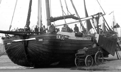
A “bomschuit” is a fishing boat from the period 1600-1900. Bomschuiten were used along the whole side, (That is the coast from Scheveningen to Den Helder) They were built in Scheveningen, Katwijk, Noordwijk, Zandvoort and Egmond. Among them they had minor differences, but the main features they all had was a length-width ratio of 2:1 and a very robust construction.
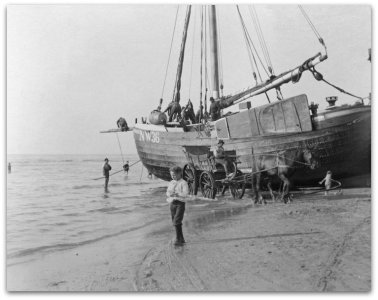
Since the places mentioned did not have a harbor, the Bomschuiten were simply sailed onto the beach and unloaded and loaded there. At the next high tide, they could go to sea again. This course of action required the robust construction. Thus, they had no keel but a heavy flat bottom.

01-1-Bomschuit.jpg

It is said that “bom” is the corruption of bottom. So a Bomschuit is a boat with a bottom.
I found a video showing how a Bomschuit is built. And this is also the way I am going to build it.
See:

The Dutch painter Mesdag painted many bomschuiten. His most famous work, however, is the “Panorama Mesdag.” This is exhibited in The Hague in the museum of the same name. It is a painting 14.6m high and 114.5m long and arranged in a circle with a diameter of 36m.
The entire painting can be seen here. https://panorama-mesdag.nl/#/micrio/intro
The painting can be viewed from a platform in the center of the circle and is then 360° around you.
In this painting you can see about a 50 Bomschuiten on the beach of Scheveningen.

Why exactly this ship?
1. I live in Hillegom in the MESDAGlaan.
2. At a distance of 20 km from Katwijk, 5 km from the coast (the side).
3. I have not seen a construction report of a Bomschuit on any model ship forum.
So that should change.

Only in De Modelbouwer of 1973-1974 I found an account of the construction of a bomschuit by N.T.A.Molenaar. He is also the designer of the construction drawing NVM 10.03.011 and the description NVM 72.10.014 from the drawing archive of the former NVM, now from another publisher.

WARNING: The drawings are still offered at https://www.modelbouwtekeningen.nl but all prices here are EXCL. VAT. Only if you want to pay will the price be increased by 21% VAT.

To get an idea of this ship, here is one of the six drawings, which best show the total ship. The other drawings will come up during construction.

01-2-Tek-1.jpg

The drawings are in 1:20 scale. This makes the dimensions of the model 1.30 m long and 1m high. And the hull only 72 cm x 32 cm and 16 cm high. So a solid model.
But I am going to make it difficult for myself. In all my previous models you have been able to notice that I hate enclosed, unviewable, spaces.
The drawings also show the interior of this ship. So I'm going to build that too. And then put the deck on and you won't see any of that.
So the deck has to remain demountable. And I'm going to do that as a cookie box. You can take off the lid of the cookie box and put it next to it. And then you can make your cookie choice and put the lid back on. Cookie box = hull, lid = deck.
That's the plan, now just the execution.

I have known for a couple of years that I am going to build the bomb barge and I was already looking for info about it. I found that there is a bomschuit club in Zandvoort that has built many bomschuit models.
I have tried a few times to get them enthusiastic to attend a model building day, but have not succeeded so far.
Therefore I am trying to become a member of this club to get them to attend with some Bomschuiten, and mine of course.

So far.
Very soon the first upate will come.
 
Update 1
Here is the first update.

Of course you start a scratch project by studying the drawings. And the best start is the line plan.

02-1-Lijnenplan.jpg

Here at the top you can see the longitudinal vertical sections. In the middle the horizontal longitudinal cross sections and at the bottom the vertical transverse cross sections.

The middle set shows with the bottom line the bottom of the Bomschuit. And that's where I started. See also the youtube video in previous post. Which starts there too.

According to the description, the bottom consists of three solid planks, the middle one to scale 5cm wide and 7.5mm thick and the two outer ones 4cm wide and equally thick.
I glued them next to each other and then you get this:
02-2-Bodem.jpg
I have also gone a step further here because you can also see here both stem ends and on
the bottom is also already indicated the place of the “kesps” as well as the place of the transverse bulkheads.
Now you can also measure the length over the stem and it is now 69cm. At scale 1:20 this gives an original length of 13.8 m.
I briefly mentioned the “kesps”, but before that, I have to show you the longitudinal section:

02-3-Langsdoorsnede.jpg

And especially this detail:

02-4-Bodemdetail.jpg
1 is the bottom, 2 is a kesp, 3 is the keelson, 4 is the lining, 6 is kufhout and 7 is a filler piece.

I have the impression that what is called “kufhout” here in the youtube video is called the “Kalven”.
Above all those crossbars comes the keelson. In keelships that is also the keelson but there it is as wide as the keel. Here the keelson is about as wide as the bottom.

On the longitudinal plan, vertical lines are drawn where in the transverse plan the truss size is drawn. From these I copied the trusses and glued them on a piece of plywood and cut them out.
This yielded a number of transverse bulkheads, indicating on a false keel the location
where the hull is to meet.

02-5-Schotten.jpg
Here are all the frames lined up for the false keel.
Once these frames are on the false keel you will get an idea of the shape of the Bomschuit.

But that's for a next time.
 
Last edited:
A Katwijk bomschuit

A “bomschuit” is a fishing boat from the period 1600-1900. Bomschuiten were used along the whole side, (That is the coast from Scheveningen to Den Helder) They were built in Scheveningen, Katwijk, Noordwijk, Zandvoort and Egmond. Among them they had minor differences, but the main features they all had was a length-width ratio of 2:1 and a very robust construction.
Since the places mentioned did not have a harbor, the Bomschuiten were simply sailed onto the beach and unloaded and loaded there. At the next high tide, they could go to sea again. This course of action required the robust construction. Thus, they had no keel but a heavy flat bottom.

View attachment 518333

It is said that “bom” is the corruption of bottom. So a Bomschuit is a boat with a bottom.
I found a video showing how a Bomschuit is built. And this is also the way I am going to build it.
See:

The Dutch painter Mesdag painted many bomschuiten. His most famous work, however, is the “Panorama Mesdag.” This is exhibited in The Hague in the museum of the same name. It is a painting 14.6m high and 114.5m long and arranged in a circle with a diameter of 36m.
The entire painting can be seen here. https://panorama-mesdag.nl/#/micrio/intro
The painting can be viewed from a platform in the center of the circle and is then 360° around you.
In this painting you can see about a 50 Bomschuiten on the beach of Scheveningen.

Why exactly this ship?
1. I live in Hillegom in the MESDAGlaan.
2. At a distance of 20 km from Katwijk, 5 km from the coast (the side).
3. I have not seen a construction report of a Bomschuit on any model ship forum.
So that should change.

Only in De Modelbouwer of 1973-1974 I found an account of the construction of a bomschuit by N.T.A.Molenaar. He is also the designer of the construction drawing NVM 10.03.011 and the description NVM 72.10.014 from the drawing archive of the former NVM, now from another publisher.

WARNING: The drawings are still offered at https://www.modelbouwtekeningen.nl but all prices here are EXCL. VAT. Only if you want to pay will the price be increased by 21% VAT.

To get an idea of this ship, here is one of the six drawings, which best show the total ship. The other drawings will come up during construction.

View attachment 518334

The drawings are in 1:20 scale. This makes the dimensions of the model 1.30 m long and 1m high. And the hull only 72 cm x 32 cm and 16 cm high. So a solid model.
But I am going to make it difficult for myself. In all my previous models you have been able to notice that I hate enclosed, unviewable, spaces.
The drawings also show the interior of this ship. So I'm going to build that too. And then put the deck on and you won't see any of that.
So the deck has to remain demountable. And I'm going to do that as a cookie box. You can take off the lid of the cookie box and put it next to it. And then you can make your cookie choice and put the lid back on. Cookie box = hull, lid = deck.
That's the plan, now just the execution.

I have known for a couple of years that I am going to build the bomb barge and I was already looking for info about it. I found that there is a bomschuit club in Zandvoort that has built many bomschuit models.
I have tried a few times to get them enthusiastic to attend a model building day, but have not succeeded so far.
Therefore I am trying to become a member of this club to get them to attend with some Bomschuiten, and mine of course.

So far.
Very soon the first upate will come.
Nice to see another scratch build of a famous fishing vessel, Jan.
Regards, Peter
 
Stephen,
Yes, that is my intention today. But..... A ship built in Katwijk mostly has a small second mast after. But a ship built in Zandvoort has not.
So I am still in doubt to do the rigging as a Zandvoort ship. Time will learn.
 
Update 2
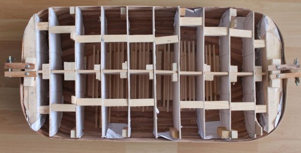
The last few days I have been busy putting together the internal framework.
Here are the trusses on the false keel:

03-1-geraamte.jpg

And seen straight ahead:

03-2-Boven.jpg

The underside of the false keel does not rest on the bottom, only the bulkheads do. If I am going to apply the first strakes then I hardly have any place to glue them against. In real life the so-called kufhouts and calves run there from the bottom slowly upwards. So I also have to apply those before the first strakes can be applied. So those have to come on the bottom under the false keel. Hence the opening. At the location of the trusses, I can apply them later. Thinking ahead !!!!!

03-3-Kesp-kier.jpg

Fore and aft, the bomschuit has a strong curvature. In order to get the strakes in the proper curvature there, I want to make the frame solid there and sand it into the proper curvature.
Therefore, I filled up the bow and stern with pine batten with a small slot in between.

03-4-boegvulling.jpg


Then I glued the bulkheads with a piece of wood at right angles to the false keel. It was all a bit wobbly. You can also see here between the first two bulkeads on the outside two spacers. This also makes the frame a bit stiffer.
Still 2x9 of these spacers to go.

03-5-totaal.jpg

The groove between the battens on the bows is to keep an eye on the lines when sanding.
From the line plan I printed out the pieces that are at the height of the slots and glued them to cardboard.
That produces these strips:
03-6-Lijnen.jpg

Do note well the location of the lines on the strip.
Now I can place these strips in the grooves and sand away the pine batten to the strip which should then produce the good lines.
This is the idea:

03-7-LijnenInGleuf.jpg

And seen from above:

03-8-LijnenVanBoven.jpg

So everything that sticks out in front of the strips has to come off.

03-9-Contramal.jpg

I also kept the contour templates, so I can measure the bevel from two sides.

To be continued

Translated with DeepL.com (free version)
 
Update 3
Another update.
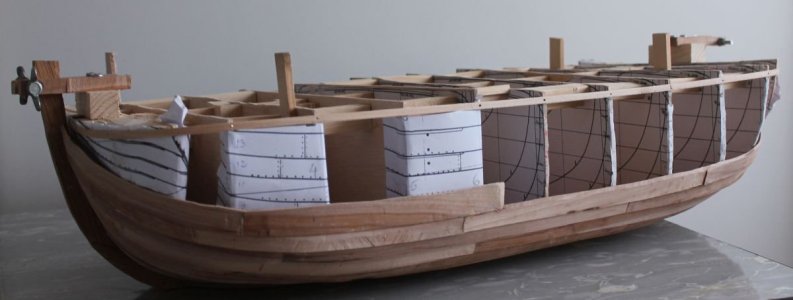
I have been busy sanding the bow and stern to get them into shape according to the lines plan.
It already looks nice. Like this on the bow:

04-1-Boeg.jpg


And so at the stern

04-2-Achtersteven.jpg


It turned out that the bulkheads on the false keel were a bit fragile and so I reinforced that a bit
that with blocks in between.


04-3-Verstevigd.jpg

The next step is applying the sand strip. This runs to the bow and the stern out wide. To get that shape I used cardboard templates. Here the sand strip At the bow:

04-4-Zandstrook-Voor.jpg


After the sand strip comes the “geerstrip” and then the first strake. This should then
straight :

04-5-GeerstrookMetTekst.jpg

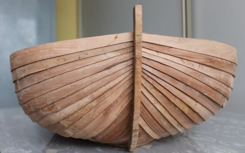
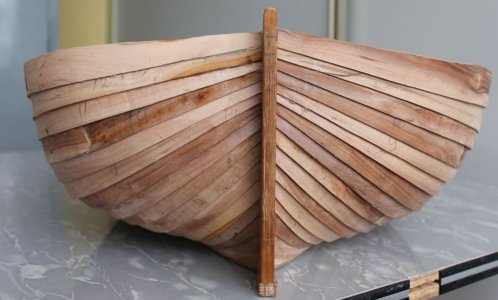
If all that goes well that should produce the typical fan shape of skin strakes as in this postcard.

04-6-Voorbeeld.jpg
But that will take some time.

To be continued.
 
Very interesting, to say the least... especially for a boat that prides itself in having a corrupt bottom! Makes me wonder about the crew, too! :p
Think I'll keep an eye on this one...
 
Update 4
Using templates, I cut and fit some strips. That not everything was immediately right is shown by the number of rejects.

04-1-probeerselsIMG_6440.jpg

But finally I had a few strips fit (sand strip and geerstrip on the bow) and replaced them with wooden strips.
With a lot of fitting and measuring and result viewing, at some point I took the bottom and stem out of the framework to look at. It looked good but unfortunately something was applied too tightly so the framework no longer fit. The bulkheads no longer met the bottom. I took pictures of it but lost them.
Conclusion: detached everything and started again and now with the framework and its bulkheads practically against the false keel.

04-2-Schot-tegen-bodem.jpg

So again I made the sand strip and geerstrip on the bow and stern to fit.
That gives the following result:

04-3-Zand-Geer.jpg

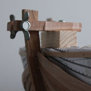
Seen straight from the bow and stern:

04-4-vvoren.jpg

And seen from the inside after temporarily removing the framework:

04-5-VBinnen.jpg

Also, between the pieces of sand strip in front and behind, the entire sand strip has been applied.

04-6-Zandstrook.jpg

And now to the first regular strakes.

To be continued

Translated with www.DeepL.com/Translator (free version)
 
Update 5
In studying the drawings, (they are from Aug. 1971) there appeared to be some differences between them. They will have been drawn manually back then because version 1 of Autocad was yet to come.

05-1-FouteTelling.jpg

Here I count 13 strakes on the left and 15 strakes on the right. There are also 13 strakes drawn on the side view as well as several other average drawings. We'll stick with 13.

Before we go any further we need to take a good look at the structure of the bottom.

05-2-Bodem-boven.jpg

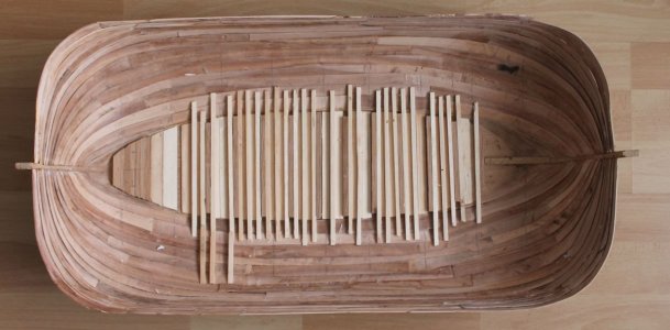
First on the bottom are the kesps. These are slightly shorter than the width of the bottom. These are applied first and served mainly to hold the three bottom planks together.
Then between two kesps lie three timbers with two fillings between them.
These timbers form the beginning of the final trusses. Since these thus run all the way through, the first strake can be fixed against this, as shown below.
This is because the first strake cannot be fastened against the sand strip because it comes practically at right angles to it.

05-3-doorsneden.jpg

So I first fitted the bottom with kesps and inserts.

05-4-Bodem-model.jpg

The kesps are of dark wood (oak) and the inlays of light colored wood (spruce).In between, also of light wood is the liner.
Not all the kesps and inlays are in place because I need to leave room to fit the internal framework.

05-5-Inhouten.jpg


Here you can see some of the inserts with the internal framework. On the side of the bulkheads is marked off to where the strakes should be. The inserts themselves are beveled to follow the shape of the framework.

05-6-Eerstegang.jpg

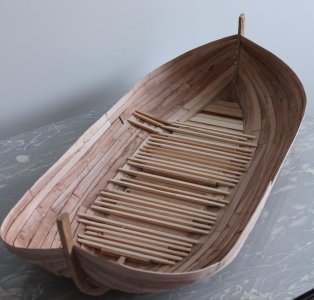
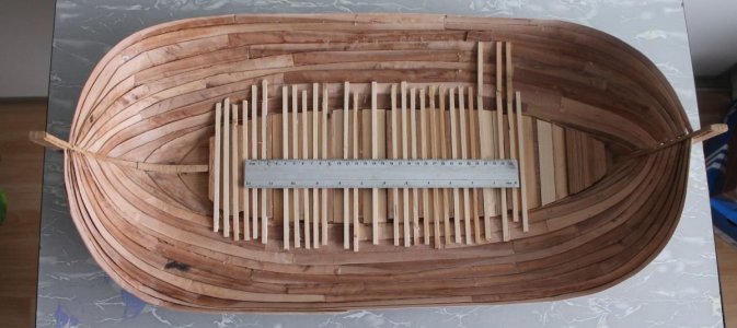
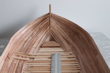
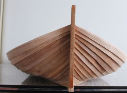
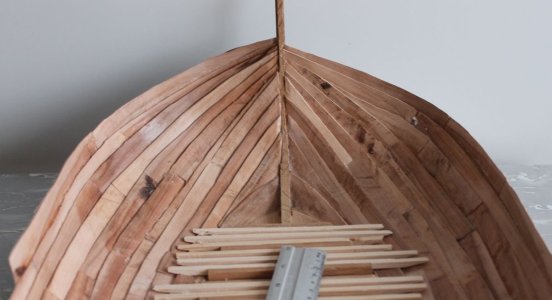
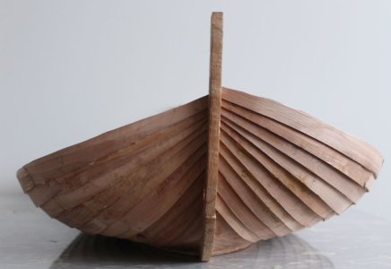
Here is the first strake applied. A sentlat can be used to see the shape.
A few more photos of the first strake inside and outside

05-7-Buiten-Voor-1e.jpg

Left = Front and right = rear.

05-8-EerstegangBinnen.jpg

Left = Front Right = Rear. In front, two more kesps can be seen and an insert.
Nothing more of this will be seen later.

To be continued.

Translated with DeepL.com (free version)
 
No, I don't know this project. And yes it looks a bit on a bomschuit. But there are also quite some differences. The bottom is not as flat as on a bomschuit. The deck of a bomschuit is nearly rectangular with rounded corners and it has no square rigged sails.
But it is nice fisherboat and saile upon the beach.
 
Last edited:
Back
Top