AGATE of Provincetown 1855, Whaling Schooner 1/64

Joined
Sep 17, 2018
Messages
567
Points
308

Location
Berlin/Germany
Hello friends,

to get a progress with my craft working skills (NOT kills!!!) I decided to restart my whaling ship's project I started in early 2019.

IMG_20190505_180145.png.b4ee668edc739c41f2424bd1b63f775a.png

Some told me not to do the third step before the first so I redraw to a smaller simpler project of less complexity. It is an us-American whaler of Provincetown from the year 1855 (Sorry for this correct is the year 1853!). Not ot too much is known about her I did got some information from the Provincetown libary about several of her journeys. Till now I was unable to research the owner's company flag or colours.

A Whaler of this time is a first fish industrial gfactory on sea. At this time nearly the half of the sighted whales escaped an d a quater to one third of their hunters were killed. So it was pretty fair battle.
IMG_20190505_175835.thumb.jpg.f63f97d9951aac7b7b927c1a973cf610.jpg

Our sources are very simple as these are two:
Howard Irving Chapelle
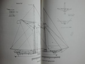
American Fishing Schooners p.80. She appears in this book as she is relatived to the Grand Banks Schooners.
IMG_20190505_175945.thumb.jpg.c98adf434cc0400286069a9f56777964.jpg
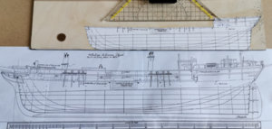
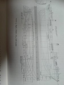
Chapelle gives a fine set of drawings to us - telling us she was built for whaling especially. Traditionally she was the last vessel of large size (Lpp 74"-10' 1/2) built at Essex/Mass. built from local white oak and pine.

The second source is also a book... the wellknown
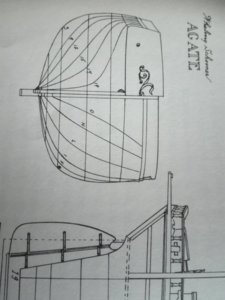
V.R.Grimwood tells us in American shipmodels and how to build them
some quite simpler drawing - but added some details
1557074223278866693822.thumb.jpg.cba5e5f08821b904981989ebda1f3719.jpg
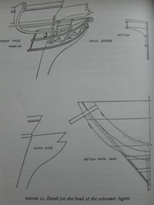
and stem decor to us

1557074881820-566213559.thumb.jpg.089fff5a6adbffc1ec1685bc4652197c.jpg
plus details of the galion. There are added

1557074691765778657388.thumb.jpg.2da30120d2c11850ac4079568eb7a7c5.jpg
deck features and some basic details.
IMG-20190507-WA0054.thumb.jpeg.c4386f9252e02f72fc9bfb9efb4ee1d5.jpeg
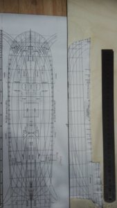
I managed to glue the centerboard's plan onto a 4mms plywood - and I managed to explore it again in the workshop.

IMG-20190507-WA0058.thumb.jpeg.3ed89b48c3aa1dfae9de31ea0e967a63.jpeg
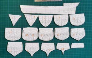
here the bulkheads...


1557352364346-1242956995.thumb.jpg.7bc0e963325e505c354eb75120ad658d.jpg
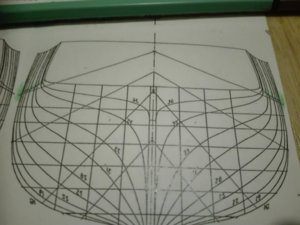
Here the frames plan from after...

1557352848526-2125813639.thumb.jpg.ffa5c1c96695670468bb376449ba4c86.jpg

from the front bulkheads.

IMG-20190719-WA0036.thumb.jpeg.d2a4e41d6cd6f9dc40e2d1c154f245a9.jpeg
Here the galley an the plan by Howard I. Chapelle.

IMG-20190719-WA0031.thumb.jpeg.12194a7feb551357953d0d218e6b6151.jpeg

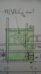
Here my drawing of the galley's sliding door ... taken from photographs collected by Church's famous book.

IMG-20190719-WA0044.thumb.jpeg.319b6295807cbe820203b4cef92e82dc.jpeg

Here my drawing of the galley.

IMG-20190719-WA0038.thumb.jpg.b22cba89f7a24c8fe282eaaecc0d8ef3.jpg
a closer look to the details of the galley. IMG-20190719-WA0041.thumb.jpeg.794f034ac04347d7786ab7056b4cd2c1.jpeg
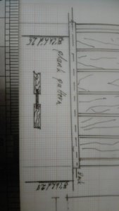
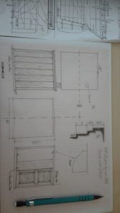
my idea of the galleys wall. IMG-20190719-WA0030.thumb.jpeg.8cdabfc9763c2237c6a6b0b7f42f0ced.jpeg

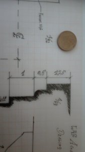
And the top galley's framing scaled in millimeters for 1/64.
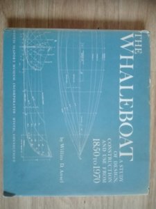
15570751354261639807556.thumb.jpg.4174e4d2d5d2ed721ff78756d8825990.jpg

So for the detailled build of the whaling boats I do have bought this interesting book - as I am always better in theory than craftmansship...
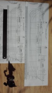
IMG-20190507-WA0052.thumb.jpeg.519119884caec833db3b97b585e1358a.jpeg
Here my trial in 1/48 and 1/64...


IMG-20190507-WA0060.thumb.jpeg.7935a0ed2c56a651e946d75572c506ec.jpeg
in 1/64 does meet the shelf board with rigging...
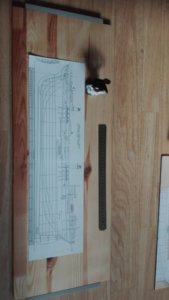
IMG-20190507-WA0062.thumb.jpeg.3b6d701d58fb4ad15bddf7f791cccc08.jpeg
...in 1/48 it is a more tight fit.

Polish_20200423_215013543.jpg
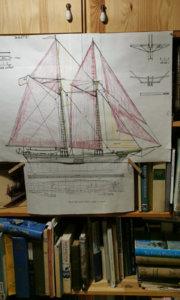
This is the situation (the Greenwood and the Chapelle's drawings clamped together) at the shelf itself; by the way
the "redly" tanned sails are wrong and only for European ships - the American cotton was cheap and so sails were white on the ships.

(Now I have to get the drawings from my archiv - but that has moved its position in the shipyard and the documents were spread over several strage boxes... :confused: )

Hope you like this little fit for better results - project.
 
Last edited:
The Model Shipwright N°92 of June 1992 came to me with an article by

Polish_20200423_221359133.jpg
Peter Rogers about his 1/30 RC-Model of AGATE starting at p.8 and at p.28 a nice Bedford Beetle Whaleboat at 1/24 gives additivly to the Ronnberg (kit's booklet to the 1/16 whalingboat) information about the detailing.
 
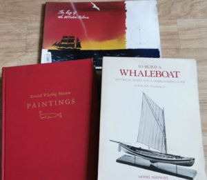
Here my major sources:

Polish_20200424_093729205.jpg
Polish_20200424_093925911.jpg
On the (up)left;) we have got:

Polish_20200424_094133414.jpg

So I am prepared by literature for the building of the boats, too. The paintings do give some very nice references.
Plus the well kown Timeline Series Book

s-l300 (1).jpg
"Whailing" giving a low tier starting point to my wife, who is interested in building AGATE,* too... :)
So I am going to get a backup by moral sewing and she gifted me a pet in form of a first prey:
Polish_20200424_095113917.jpg
So let's go to the dusty inside of my archiv - pick out those plan set - making that reboot!
________
*her book is the German translation.
 
Last edited:
And so elsome hours later I did managed to figure out hiw to be able to find the
Polish_20200424_120520498.jpg
prototype for the bulkheads in 1/64 and a complet enlarged set of copies in 1/48...

Polish_20200424_121113052.jpg

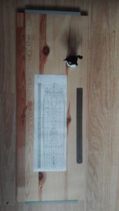
But also the original frostpaper drawing and my "SOS-steel lineal" (imperial and metric gauge) reappeared.

So we have collected all we ne for the start (and I do have now to walk calmly to my copyshop to multiplicate the bulkheads drawings).

I have to recognize that proper archivation really isn't my top skill, too.

See you later!
 
Last edited:
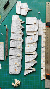
Cutting out the bulkheads copies and

Polish_20200424_173121770.jpg
gluing them on to 4mms thick beechwood ply boards was the last step for today and till next week.

Polish_20200424_175203433.jpg
Here some very much less spectacular transom than those I dealed with before.

Take care of you and enjoy your weekend.
 
Last edited:
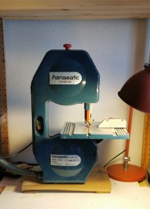
THE BANDSAW

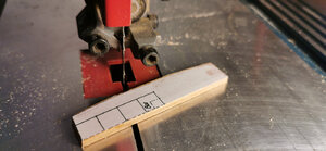
Today I tested my band saw - and had to figure out how the hell to fit in a new sawing band into the machine...

and in what direction? The last time I did it was 34 years ago :eek:

Polish_20200429_181528289.jpg

So I am very happy with the result as the band saw ist more accurate and doesn't swing and shake so much as the electric jigsaw so - here todays output.

THE DECK'S LNE

Due to the fact that I am unshure how to constuct the deck I did not cut my reference-line gone & away as I am unshure how thick the deck will be. I have got a good pile of marpel vaneer. The thickness is 0,7mm but I still think about the underconstruction of the deck - what thickness of the plywood is best? And certainly I am still dreaming of an open staircase for a bit of a view downwards.

SHIPYARDS'S OUTPUT

But the result is amazingly fine when trying to cut ON the line - I am pleased with the result very much.
IMG-20200429-WA0008.jpeg

so there is not too much to sand away.

IMG-20200429-WA0006.jpeg
In the curve I did left some wood as a sanding additive.

Polish_20200429_183512773.jpg
I have got the Proxxon UHZ at ebay and
want to construct a miniature table and a kind of drum sander with my Proxxon hand drill. Has any body of you build something like this and has still got the drawing of the construction?

Thanks for the likes and your tolerance it really helps me out of my darkgrey times...
 
Last edited:
Hello friends,

here some news about the recent progress from the band saw:
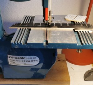
Polish_20200430_144148794.jpg

Wonderfull machine but lagging an arm problem....

SHORT ARMS

Do you guess why???

Polish_20200430_142540094.jpg

Due to the length of the centerboard :oops:
of 370mm* I do run in troubles... *
So I decided to spray the backside black precut the lines on the Proxxon small table saw and

Polish_20200430_142621443.jpg
"Let's krack on!" (Thanks to Charly Bishop from Chadwick learning me moddrn English!)

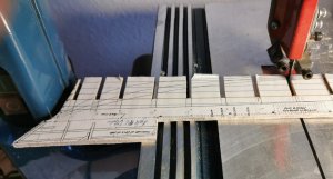
DECK'S RULER
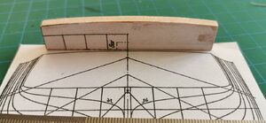
Now I have to build a decks curve ruler to saw out the decks line what is only drawn in until the main frame... after this it dissapieared...

So I decided to pick up Nigel's idea and build it from scrap piece of cut off.

Polish_20200430_150006236.jpg
And to work more precicely I used water line N°4 as my lower point of reference. I do get by this the other side of my "decks ruler" I have to take allways a refrence to the distance +/- to this walerline

Polish_20200430_144725032.jpg


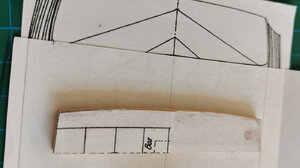
Here you can see the clear wet parts from using Uhu to fix and getting a hardened surface.

IMG-20200430-WA0023.jpeg
And before the 2nd sanding I think I will "dipp" ;) the curved part into superglue to give it some extra hard surface - hopefully.

Now I have to wait for the glue to go**...

________
*At TONNANT/SAINT PHILIPPE the centerboard is about 830mm!!! I have no idea how to deal with this - so it was a good idea to stop and start some smaller model in the same scale I start to think more and more.
**Interstingly nobody ever told me*** where the glue is going to... Do you know?
***...there is also the very unanserwed question:
"How many pints are in a nautical mile?"
 
Last edited:
Here the next step from the decks ruler:

Polish_20200430_161027198.jpg
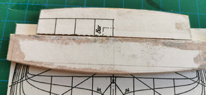
Sanding on the disk sander is the lower line the upper line is done with 600 grain sanding paper by hand.

Praise the handcrafted work!IMG-20200430-WA0029.jpeg
Freshly dipped by superglue to get some more egalitarian surcace.
 
1st STEPS WITH THE WHALING BOAT TRIO

Hello,

this evening I got the possibility to reduce my copies of the whaling boats for the ship - plans from Willits D. Ansel's book THE WHALEBOAT A Study of construction design and use from 1850 to 1970. As there will be three boats (a pair in the side davits ond on the beams over the transom). I decided to build one of them on a mould from cardboard or vaneer. As I have got no experience I was terrified by the idea to work on such tiny boats:

Polish_20200430_222419359.jpg
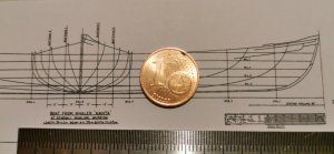
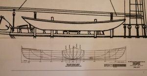
But I decided to use the drawing of the 28'8-3/4" restored whale boat from Mystic Seaport for several reasons...

So as the length of the whalingboats aboard is given by the author by 28ft - the nearly 3/4ft is a tolerance I hopefully can live with. But is this right to do so - as the bboat might have been called "29ft whalingboat"? As you are natural speakers what is sd our opinion due to the length of a boat?

Polish_20200430_223836790.jpg
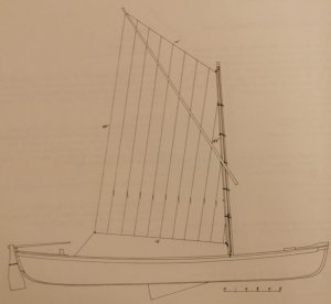
The rigg will be a spritsail this example is from 1845 quite close to AGATE's birthday in 1855. So I will combine the most simple and oldest given sailing rigg with the best documented boat I was able to find. But is this correct from the historical point of view?

Polish_20200430_223932931.jpg
As in the collection of 8 plans within the beautyfull and vwry helpfull book it is the plan with a complete wooden plan - so I thought I couldn't go wrong with this, couldn't I?

Polish_20200430_222322053.jpg
Here the frames plan that looks quite identical fore and aft.

But there is one very irritating thing to think about...

THE SCALE QUESTION
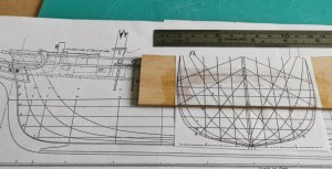
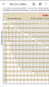
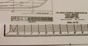
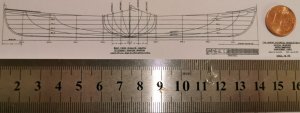
I cut off the 1/64 scaled ruler from the very reliable plan of H. I. Chapelle of AGATE and I have got the spread sheet from Finescale modellers download site is telling me I would have to reduce the scale from the given 1'=1" or 1/12
Polish_20200430_223725827.jpg
down to 1/64 by using 18,7%. As the copying machine only reduces down to 25% I did reduce it down to 50% and than again to 37,4% - or with this machine 37%

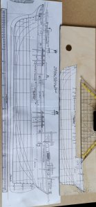
Polish_20200501_022426615.jpg
and I had to admit the given boat does fit quite nice to the 1/64 side view. So it does looked well untill I did the Polish_20200430_222248400.jpg
scale ruler comparison and failed completly!!!

Has anybody any idea why the boats size does fit but not the scale rulers? So why do the ruler's measurements not going to match in any way?

What did I do so terrebly wrong?
 
Last edited:
Hello as I am refitting the mast's slots I have to
IMG-20200508-WA0022.jpeg
figure out where the deck openings are


IMG-20200508-WA0024.jpeg
and how many degrees the fall of each mast has to be and what diameter is the the right one for each mast.

IMG-20200508-WA0026.jpeg

Here the pair of grooves for both masts. Daily target archived!

Todays surplus is told to me to be sanding in beautyful golden glitter:
IMG-20200508-WA0028.jpeg

And I am so happy!

IMG-20200508-WA0033.jpeg
The thickness of this nail sander is 4,0mm exactly as the grooves have to be. Sometimes Fortuna is our figurehead!
 
Last edited:
Thanks for your interest and likes from all of you!

HIDDEN RULER

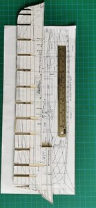
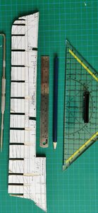
As my old decks shape "ruler" just wasn't as good as I wanted him he run away dissappeared and has hidden somewhere in my shipvyard's workshop so let's make a new & better one:
IMG-20200508-WA0037.jpeg
 
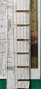
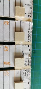
Now it is time to apply the frame stoppers precisely:
Polish_20200508_142701999.jpg
so I can fix the steel ruler on the center board and glue the Stoppers onto it. In the middle you can see the very fist conter-stopper glued onto frame 31BELOW warerline N°4 (coloured in orange).

Polish_20200508_145223007.jpg
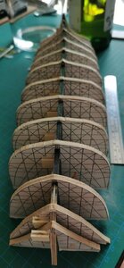
Here todays final output it will dry its way over the weekend and on monday we will look at the very result - hopefully.

IMG-20200508-WA0049.jpeg
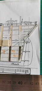
As you have seen the WLn°4 is bent... so I corrected it by placing the steel ruler to get a straight line of stoppers. The stoppers are straight now - so the decksline will be a millimeter less low than drawn by Chapelle.

IMG-20200508-WA0052.jpegI hope Thisis the very result of this at the main frame. Due to the differences in the hight I hope and think I can handle this by sanding the decks line a bit more towards the main frame to come closer to a correct decksline.

What do you think?

P. S. :

IMG-20200508-WA0054.jpeg
I just couldn't withstand to do a first testfit.
 
Last edited:
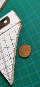
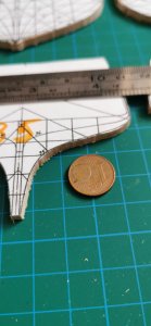
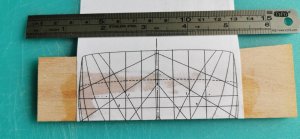
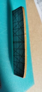
So here I am with the topic of the transom. There is a convex area bent 1,5mm in hight and with a edge of 64, 5° to the WL.

IMG-20200514-WA0075.jpeg

The area is between 23mm at the sides and 26mm in the middle high. On the top runs a beam 1,2mm high:

IMG-20200514-WA0073.jpeg
So the transom is a tricky bit of a part of the hull's construction.

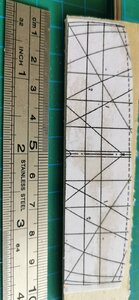
Polish_20200514_190154405.jpg
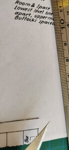
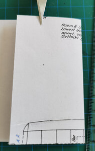
I copied my technique from the whaling boat's frames to

Polish_20200514_190143094.jpg
fold the second half of the paper under the frames line...

Polish_20200514_190154405.jpg
...along the CL by scratching a groove into the paper...

Polish_20200514_190222880.jpg
...and cut the line of the frame out as exactly as I am able to do.

Polish_20200514_190250079.jpg
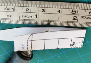
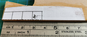
...the I glued it onto the beech plywood's fitting cutoff...

Polish_20200514_190310020.jpg
...cut off what wasn't needed...

Polish_20200514_190328815.jpg
...used the little additive wood for sanding machinery work...

Polish_20200514_190343626.jpg
...and got my upper horizontal transom's frame.

Polish_20200514_190451967.jpg
The lower frame had had to the curved in the very same way...

Polish_20200514_190526574.jpg
So I used the upper frame as a curved ruler, took the triangle of the lifting onto the other side and wasvby this able to copy my line from the portside in a second run...

Polish_20200514_190551425.jpg
... cut it off the paper and glued it on the same pice of cutoff and after doubling my same procedure from above I got the lower horizontal transom's frame.

Polish_20200514_190629770.jpg

Here we do see both frames together...

Polish_20200514_192354751.jpg
the length is right at the upper and the lower boardside and...

Polish_20200514_192408932.jpg
...also the curves do look quite parallel.

So I hopefully can put these parts aside to use them later on.

My idea is to fill them like a multi breadslips sandwitch with layers of softwood. So I want to sand this pile of wood with hardwood fames into shape. What I was affraid of disappeare immediadly when I calculated that the angle of inclination of the hull's sides will come into the construction by this sanding, too.

IMG-20200514-WA0115.jpeg
So I will get a solid "transom block" that will give the sides planking a good surface where they will be bond onto.

Are my ideas right or is there any error in my future's calculation. Or are there in this construction any mistakes I did not be aware of?
 
Last edited:
Yes I did something absolutly braindead and completly wrong...

IMG-20200514-WA0117.jpeg
The upper frome is pircing the deck with the half of it's body. So I am in real trouble!

What is to do about this horrible mess?
 
Back
Top