• Ships of Scale has incorportated an extra level of security when you log In. Please follow on-screen prompts to acknowledge that you are not a robot via a "Check Box" or a "Pictorial Check Box Puzzle". This is needed due to higher level of AI Activity Security.
  • SUBSCRIBE TO SHIPS IN SCALE TODAY!

    The beloved Ships in Scale Magazine is back and charting a new course for 2026!
    Discover new skills, new techniques, and new inspirations in every issue.

    NOTE THAT OUR NEXT ISSUE WILL BE July/August 2026
  • Win a Free Custom Engraved Brass Coin!!!
    As a way to introduce our brass coins to the community, we will raffle off a free coin during the month of August. Follow link ABOVE for instructions for entering.

Albatross by CharlesEdward – Constructo - 1/55 –

September 20, 2026
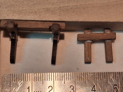
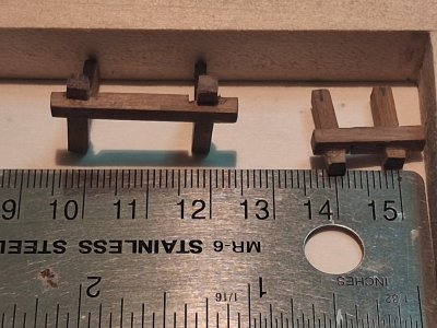
Finishing manual Page 30 of instructions: Davit’s Installation. The Davits comparison photo.
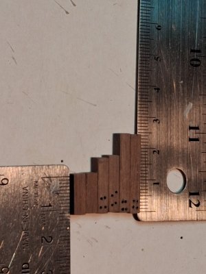
Photo_01.jpg

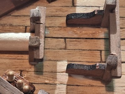
This photo comments on the installed Davits:
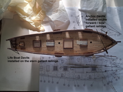
Photo_02.png

Manual Page 32 of instructions: Foremast and Mainmast channels installation.

Using the 1.5 x 5 mm boards, shape two each of part 40 and part 41, with part 40 being the foremast channels at a length of 30 mm and part 41 the mainmast channels at a length of 26 mm. Notch the five notches on #40 and the three notches on #41 and attach to the outboard bulwark positioned to match the plan.

Photo of the installed channels both fore and main mast.
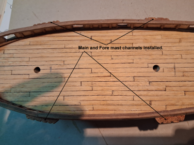

Photo_03.png

The port side installed channels, I just used white wood glue and masking tape to set the parts onto the hull. [Photo_10]
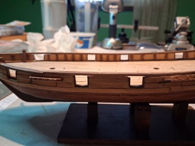

Photo_10.jpg

Manual Page 40 of instructions: Cap Scuttles installation.

Using 1.5 x 4 mm stock make up parts 54, 55, 56, 57, and 58; cut seven Part #54 from 1.5 x 4 x 28 mm. strip, two Parts #55 and two Parts #56 are 1.5 x 4 x 29 mm. and 1.5 x 4 x 33 mm. Sepelli wood strips, and two Parts #57 and two Parts # 58 are from 2 x 2 x 33 mm. 2 x 2 x 37 mm. Manzonian wood strips. Follow the instructions and illustrations to complete the Cap Scuttles part.

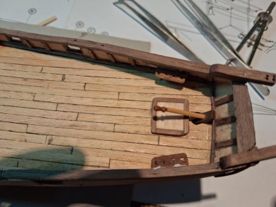
The cap scuttles and helmsman base before the frames are installed.
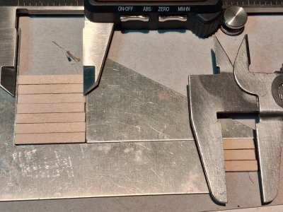
Photo_4.jpg

Framing the cap scuttle.

Photo_05.jpg

Cap Scuttle drying.

Photo_06.jpg

Manual Page 42 of instructions: Helmsman Base and frames and the included pre-cut Capstan installation.

Very similar to Page 40 of instructions above; Cut Parts 59, 60, 61, and find 62; but this time only three Parts #59 using 1.5 x 4 x14 mm. Sepelli wood strips, then two Parts #60 and two Parts #61 from 2 x 2 x 2 x 13 mm. and 2 x 2 x 19 mm. to form a frame around the base from Manzonian
wood strips. The Helmsman base awaiting framing.
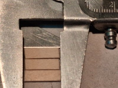
Photo_07.jpg
The Helmsman base frames are just 2 x 2 x 14 and 16 mm. This is An extreme closeup showing that the caliper is set to 14 mm. [Photo_08]
An extra photo of the digital caliper reading of the cap scuttle parts before gluing them to each other. [Photo_09]
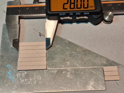
Photo_09.jpg

Coming up next Manual Page 34 of instructions: Fore pinrails, Foremast & Mainmast pin racks.

Thanks for checking in, until next time.
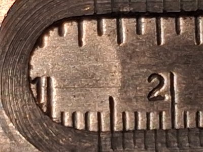
Photo_08.jpg
 
September 21, 2026

Manual Page 34 of instructions: Fore pinrails, Foremast & Mainmast pin racks.

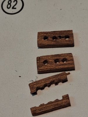
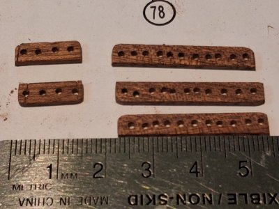
The pinrails and pin racks consist of three different numbered parts; two Parts #42, four Parts #43, and two Parts #44, all made from 1.5 x 4(5) Sepelli with lengths of 11 mm, 32 mm, and 15 mm, respectively. I have the 4(5) mm. listed as such because I could only find the 5 mm wide stock, there was no 4 mm wide stock included in the kit, so I have always been using the 5 mm stock for both 4 and 5 mm parts.

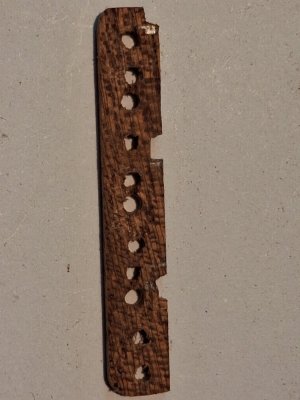
Cut the parts listed above and mark where the holes are based on the plan illustration. Drill 1.5 mm. diameter holes to fit the belaying pins for future rigging of the model. Now to do this correctly I used a 1 mm drill bit to start and used math to drill the holes in the center of each part, then half the distance to mark the next center and fill in the remaining holes based on the plan. I decided to drill all of the holes before I cut each of the pieces to the required length. Finally used a 1.5 mm. bit to make the holes the correct diameter and dry fitted each and every one with a belaying pin.

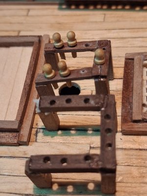
This photo shows the three parts needed for all of the pin racks, the two smaller parts have four holes but the smallest one should only have three holes, per the rigging instructions.

Photo_01 Commented.png

There are only 47 belaying pins included in the kit so not all of the pin racks will be filled with belaying pins, only the ones needed for rigging.
All four of the Parts #43 showing below.

Photo_02 Commented.png

I broke one of the smallest pin racks and had to replace it.

Photo_03.jpg

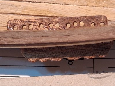
This magnified photo shows the cut-out I had to make on this particular pin rail to fit on the bulwarks with the rough timbers. I actually did install this one where it belongs along the starboard fore mast.

Photo_04.jpg

Since I have installed the two fore pinrails and one of the Main / Fore mast pinrails, There are only two Parts #44, (15 mm length), and three remaining Parts #43, (32 mm in length), ready for installation along the bulwarks. The Part #43 required 11 pin holes at 1.5 mm diameter.

Photo_05.jpg

The fore pinrails shown installed, however the port side one broke in half when I tried to twist the belaying pins in the holes. I actually repaired it with superglue and at the same time installed the three belaying pins required for the rigging later. I had forgotten how hard these sometimes are to rig being so small.


Photo_06.jpg

The installed Part #43 on the Starboard Foremast, I used a drop of super glue to the ends but white wood glue to all of the between areas.


Photo_07.jpg

An unmarked photo of the Part #43 to be installed next time.

Photo_02.jpg

Next up the completion of installing all of the pinrails and pinracks along the bulwarks.

Thanks for checking in, until next time.
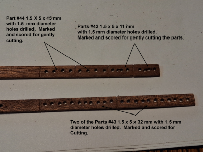
 
Last edited:
September 21, 2026 – Second Posting

Completion of Manual Page 34 of instructions:
Fore pinrails, Foremast pin racks and Mainmast.

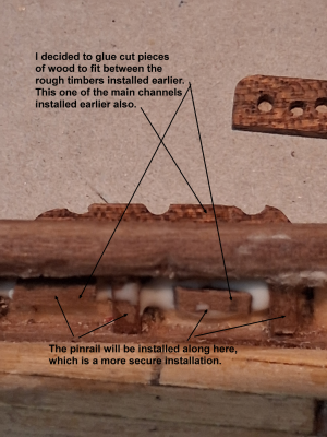
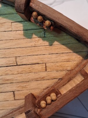
So what I decided to do with the remaining pinrails and pinracks is to glue pieces of wood along the bulwarks where the pinrails will be installed, instead of cutting out 1 or 2 mm notches to install the part. This proved to be much easier and does the job better as it extends the pinrails out about 2 mm, which will make it easier to rig up the belaying pins when needed.

Photo_06 Commented.png

A photo of all of the pinrails / pinracks installed, (Parts 42, 43, and 44), onto fill-in wood pieces for easier and stabler installation, and ready for rigging.

Photo_07.jpg

A closeup of the Helmsman base installed under the tiller as well as the stern pinracks Part #44.

Photo_08.jpg

Installed Parts #43 along the Mainmast area of the model.

Photo_09.jpg

Installed Parts #43 along the Formast area of the model, as well as the fore pinrails.

Photo_10.jpg

Coming up next, I will show the installation of all of the deck furnishings that are required by the manual instructions.

Thanks for checking in, until next time.
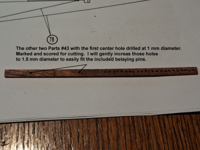
 
Last edited:
September 23, 2026

All Deck Furnishings Installed onto the Main deck.
As promised in the last post, the installation of all of the deck furnishings that are required by the manual instructions, up to this point.

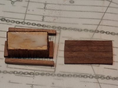
The final deck furnishing is the Logbook Cupboard, which includes a pre-cut Part #63, using several 0.5 mm Sepelli veneer board to plank all of the sides, a couple of base frames made from 2 x 2 mm boards and roof pieces made from 1 x 3 x 24 mm Manzonia board.

The Logbook Cupboard under construction, showing the base pieces and the drying glue waiting for me to place the roof assembly on the right of the picture.

Photo_01.jpg

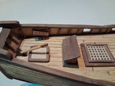
The finished logbook cupboard installed in place on the main deck of the model near the Helmsman base. Also a look at the life boat davits, stern pinrails, tiller and aft grating hatch.

Photo_02.jpg

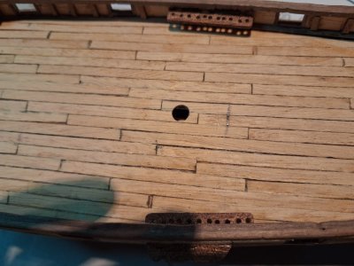
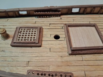
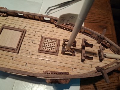
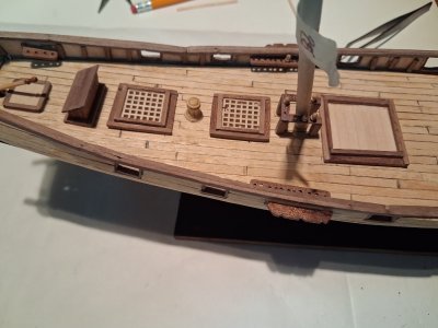
A view of the installed capstan, Midships grating hatch, Main pinrails, main mast deck hole and Cap Scuttles.

Photo_03.jpg

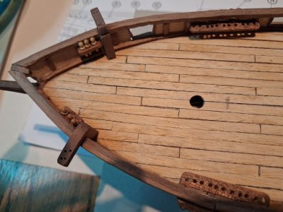
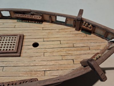
The installed Foremast Pinrails, anchor davits, Fore pinrails and forward grating hatch, with the foremast deck hole.

Photo_04.jpg

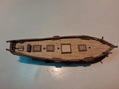
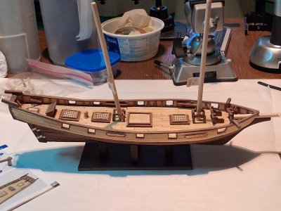
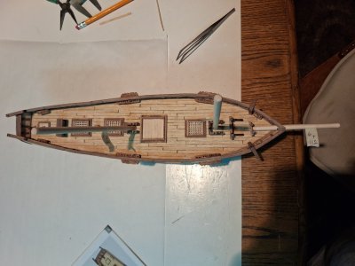
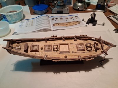
Overhead angle of the current main deck furnishings layout all installed for better or for worse.

Photo_05.jpg
Manual Page 46 of instructions: Mast pinrails, both Fore and Main pinracks installation.

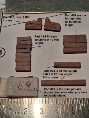
Consists of Parts # 68, 69, 70, 71, 72, and 73; using 3 x 3 mm stock make up parts 68, Pin rack columns, (length of 10 mm – eights pieces required), 70, Bitt Uprights, (length of 16 mm – four pieces needed), 71, one Bitt Cross, (length of 29 mm), and one 73, a longer Bitt Cross, (length of 18 mm), and finishing using up the 1 x 3 mm stock left to make six Parts #69, Mast Pinrails which will need three 1.5 mm holes in each of the six parts for the belaying pins to be installed later. This time because the six parts basically use all that is left of the 1 x 3 mm boards included in the kit, I cut them all first and checked the length of 14 mm, planning to drill the holes later. Part #72, Bitt Curve, is precut and in parts pack #4.

NOTE: There is a final part #114 that will use almost all of the remaining 3 x 3 mm board as it is 16 mm in length and there are eight pieces required, (total 128 mm.), so a total use of approximately 319 mm of wood stock, which is just about the size of the last 3 x 3 mm board included in the kit.

This section has proven to be quite difficult and some of it is caused by the kit including impossible widths of wood stock to drill three 1.5 mm diameter holes into all six Parts #69. The length required in the instructions are really NOT helpful and I should have bashed the parts with a better piece of wood, after all I have loads of lumber I purchased from some online ship model lumberyard that was going out of business years ago and was having a big sale of almost all of their remaining stock. This includes 2 x 3 mm boards that I had to substitute for the Foremast Pinrails piece that I destroyed, so I have to replace it. This wood board could handle the three 1.5 mm holes much better than the original 1 x 3 mm boards that I used following instructions. I split almost all the cut boards while drilling only the starter hole of 1 mm drill bit size. Fixed most with liberal application of superglue, but the broken foremast pinrails was just not usable anymore.
It took most of the day to cut all of the necessary pieces per instructions and shown below are all the pieces cut. I should have added a tad more length to two of the Part #69 to make room for the three 1.5 mm diameter holes since those pieces are short and therefore crowding out the two outer holes making it harder to rig those belaying pins.

Photo_06 Comments.png

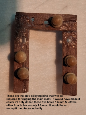
I was thinking about the belaying pins included in the kit only number 49 or 47 parts, not enough to put a belaying pin into every pin hole on the pinrails, so I studied the rigging plans and found out that the Mainmast Pinrails would only be using the below pins for rigging, not the entire 9 holes that I drilled. This would have been more helpful if I noticed it before I made the parts.

Photo_07 Comments.png

The Mainmast Pinrails may only use five of the holes for belaying pins for the rigging plan, however the Foremast Pinrails need to use all nine holes filled with belaying pins for rigging. Knowing this now I thought about how to make this next Pinrails part and decided that, besides substituting 2 x 3 mm boards for Part #69, (1 x 3 mm boards), that I would make one of the pieces, the piece that is at the bottom or top, (depending if you see an upside down ‘U’ or a normal ‘U’), of the U-shape piece should be a little bit longer in length. This would not IMHO cause it to look too big for the Foremast plus give me more room to drill the 1.5 mm holes in all of those parts.

Photo_08.jpg

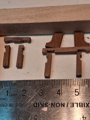
Per the instructions I have to cut out recesses in Part #70 to fit both of the Bitt Crosses. I will do this by sawing the 3 mm notch and then use a series of needle files to square out the notch, I am not sure if it wants me to do the same for the Bitt Crosses, but it would make sense to do so. [Photo_09 showing notched Bitt Uprights and Bitt Crosses?]

Photo_09.jpg

The installed Bitts and Pinrails on the main deck of the model, the Bitts are not yet glued to the deck, I have to check the position of both of those parts before I glue.

Photo_10.jpg

Next up, the continuation of the instruction manual Page #46, finishing and installing the mast pinrails.

Thanks for checking in, until next time.
 
September 24, 2026

Here are some extra photos that I took while constructing the Bitts and others, just wanted to share in the spirit of full disclosure.

The two Bitt parts completed, the one on the left is the Anchor Bitt and bitt cross, while the small one to the right is the Bowsprit Bitt and cross Bitt.

Photo_01.jpg

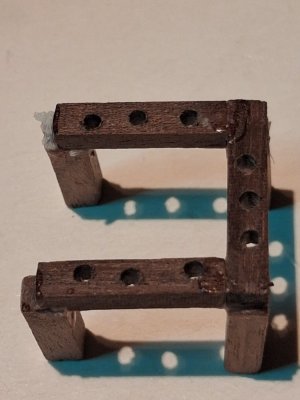
The terrible looking mainmast pinrails are just not as good as the replacement part for the broken Foremast pinracks. I almost want to rip out the main mast pinrails to recreate that piece in a better-looking form. After seeing this photo, I would make the side pinrails about 2 mm longer to look much better and have more space for the pinrails columns, the rigging of those belaying pins will be much easier.

Photo_02.jpg

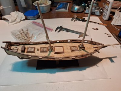
An overview shot of all of the current deck furnishings laid out onto the main deck, I used the main, foremast and bowsprit for reference to the placement of each piece.

Photo_03.jpg

The Foremast pinracks, anchor bitt and bowsprit bitt in position but the two bitts are not glued yet, just dry fitted for the final placement of them.

Photo_04.jpg

The cap scuttle mainmast pinracks, midship grating hatch, capstan, aft grating hatch, the logbook cupboard, and the Helmsman base and tiller on deck.

Photo_05.jpg

Starboard side view of the deck furnishings before I finished the two pinracks and Bitts.

Photo_06.jpg

Starboard side view of the two added pinracks using the masts and bowsprit as position reference.

Photo_07.jpg

The two Bitts again, just a clean photo of the two parts before gluing onto the deck.

Photo_08.jpg

The tow bitts accurately positioned onto the deck with the glue drying.

Photo_09.jpg
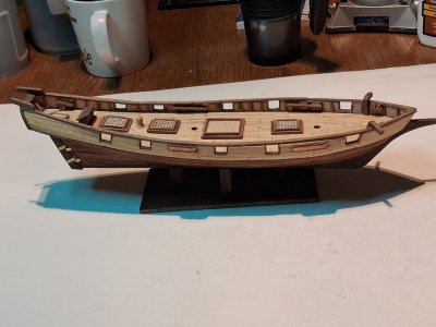
The full view of all of the deck furnishings sans the masts for a better view, the bowsprit is still for reference positioning.

Photo_10.jpg

Next up, the installation of the deadeyes onto the Main and Foremast channels.

Thanks for checking in, until next time.
 
September 25, 2026

Manual Page 48 of instructions: Deadeye installation onto the Main and Foremast channels.

This step consists of Parts #14, #74, and #75; the nails in parts pack 1, the Deadeyes in parts pack 5, (32 of them), and the rigging screws in parts pack 12, the 0.05 mm wire by 50 mm, 16 of them).

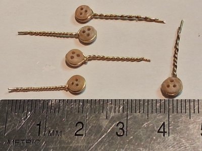
Cut part 75, Deadeye Screws, and plait them around the deadeyes, part 74. Use a 1.0 mm bit to drill corresponding holes to take the Deadeye screws and fix in place using the nails part 14. Since you have to use superglue to install the Deadeye Screws into the hull, why use Part #14, nails anyway, so I opted out to just use superglue, forget the nails. You have to drill 1 mm holes anyway so the deadeye screws work by just a dab of glue and insert with a needle nose plier.

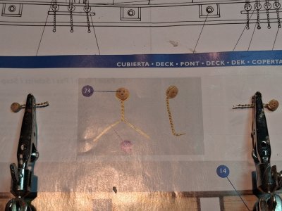
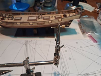
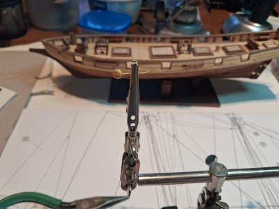
Comparison of what the instruction manual pictures and my results that I got when I did the plaiting myself. The right one has the bends in the part, while the left one doesn’t.

Photo_01.jpg

A closeup of the completed deadeye and deadeye screw with the bends for the deadeye and end of screws.


Photo_03.jpg

The unbent Deadeye / Deadeye Screw, ready to be bent.

Photo_02.jpg

The unbent Deadeye / Deadeye Screw, ready to be bent.

Photo_03.jpg

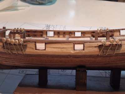
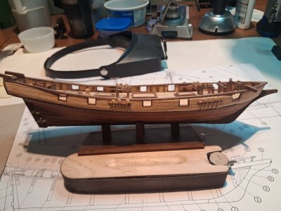
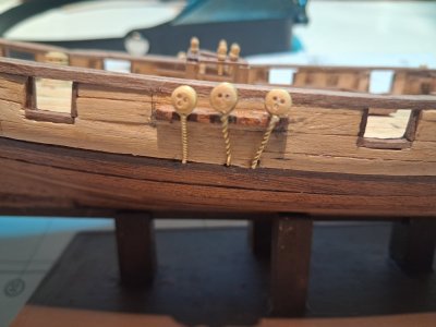
This is a photo of the Port side Fore and Main channels with the deadeyes glued into place.

Photo_04.jpg

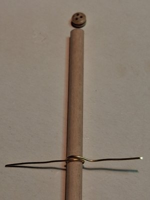
I found a scrap wood dowel that matches the diameter of the Deadeyes I am trying to make, then start twisting with my thumb and forefinger until the wire sets into the deadeye grove. The picture below shows a 4 mm. dowel which is the same diameter of the deadeye and start a circle that matches the dowel, and then gently slip it over the deadeye like a noose, and once the plait starts I use needle pliers to hold the deadeye and another one to twists or plait the wire around the deadeyes.

Photo_05.jpg

Th five last deadeyes ready to be installed onto the starboard channels. Note that all of the deadeye holes are set in the correct direction of down, than I dabbed a bit of superglue to secure it for th rigging tasks coming up later, they all do look pretty good.

Photo_06.jpg

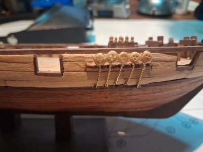
The deadeyes are installed on the Starboard side channels.

Photo_07.jpg

Closeup of the starboard main mast channels and deadeyes.

Photo_08.jpg

Closeup of the starboard foremast channels and deadeyes.

Photo_09.jpg

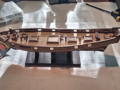
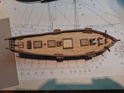
An overhead shot of the current model main deck with all of the furnishings finally installed.

Photo_10.jpg

Coming up Next will be installing the anchors Manual Page 50 of instructions.

Thanks for checking in, until next time.
 
Last edited:
September 27, 2026

Manual Page 50 of instructions: Assembly of the anchors.

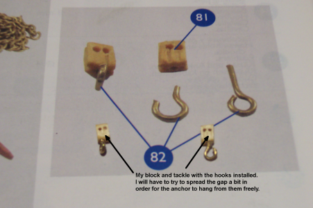
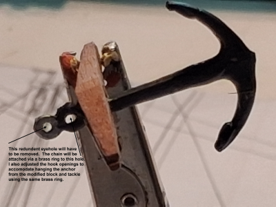
Includes Parts #76 through #82 ,(2 Eyebolts modified to become a hook), all in parts pack #4, 5, 6, and 7. I must have broken 4 or 5 eyebolts trying to modify them to be a hook. I don’t know what I will do for this but will think of something. Another thing I was totally flummoxed that I could not hook the anchor hole with my hook blocks, frustrating to say they least, then after a good night’s sleep, I realized that since I have to connect the anchor chain to the anchor via a couple of brass rings anyway that I could also use those same brass rings to hang the anchor from the block and tackle with the hook installed. Breaking out my tackle box of rigging tools, threads and wax I started getting ready for my first rigging task on this model, hmmm I have quite a collection of great rigging tools, I had forgotten.

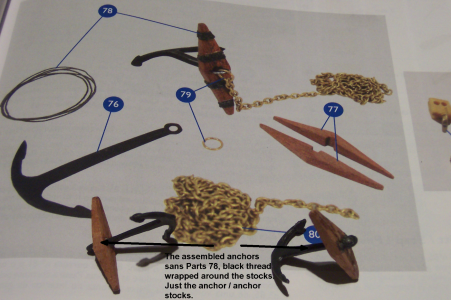
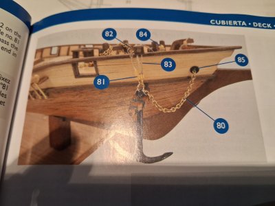
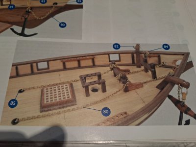
Parts #76 are the 2 metal pre-molded Anchors, #77 are the four pre-cut wooden anchor stocks, #78 is the Black Thread to be used to tie together the two anchor stocks, #79 are the 2 rings, #80 is the Chain pieces to be cut into two 280 mm lengths, #81 are the two 3 mm block and tackle, and #82 are the two eyebolts to be modified into a hook, (see manual instructions / photos). A comparison photo using the instruction manual for reference.

Photo_01 Comments.png
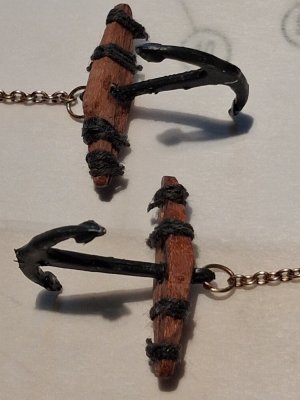
The plain un-accessorized assembled anchor and anchor stocks, I will have to trim one hole from the anchor pieces, I also painted the plain metal anchors black.

Photo_02 Commented.png
The assembled anchors with the instruction manual backdrop for comparison.

Photo_03 Commented.png
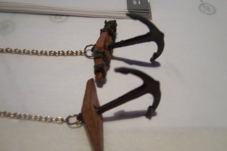
The two anchors with connected chains using the brass ring; one with the Part #78 threads installed and the other one no thread yet. I am thinking not to wrap so many threads for the second anchor for a cleaner look.

Photo_04.JPG With the completion of the two anchors linked to the chains, this completes this posting of this build log.

Photo_05.jpg
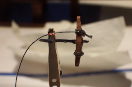
An additional photo of the wrapping part 78 process during that step.

Photo_06.JPG

Coming up next: Installation of the Anchors onto the Model.

Thanks for checking in, until next time.
 
Looking at some other posts and it looks like I reversed my anchor's stock facing the sloping end toward the anchor instead of toward the end of the anchor. Oh well live and learn, I actually struggled with this decision for hours wondering what was correct. Guess I should have done a bit more research on this web forum first.
 
September 28, 2026

Today I post the last few days of work on the model.

Manual Page 52 of instructions: Installation of anchors onto the model.

Includes Parts #82 through #85, all in parts pack #6, 7, and 8.

Parts #82, (2 Eyebolts to be inserted into both port / starboard anchor davits on the leeward side), 83, (Beige Thin Thread), parts #84, (2 Belaying Pins already installed into the fore pinrails as rigging pin 43, both port / starboard, finally parts #85, (four Hawse holes and Open Chocks).

The photo below shows the instruction manual illustrations for the hull installation step, note that you install the hawse holes from the outboard bulwarks side.

Photo_01.jpg

This next photo shows the instruction manual illustrations for the deck installation step, see the hawse holes #85 installed to accommodate the insertion of the end of the anchor chain.

Photo_02.jpg

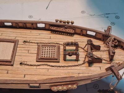
I needed to drill two 4 mm. holes in the deck and two 4 mm holes in the bow bulwarks to insert four Parts #85, Hawse Hole / Open Chocks. As shown in the instruction manual, insert the Hawse Holes from the outboard bulwarks on the bow to run the chains through and insert the end of the chains into the Hawse Holes on deck, to let it hang. The photo below shows the chains laying on the deck looking toward the port side with everything seemingly looking good.

Photo_03.jpg

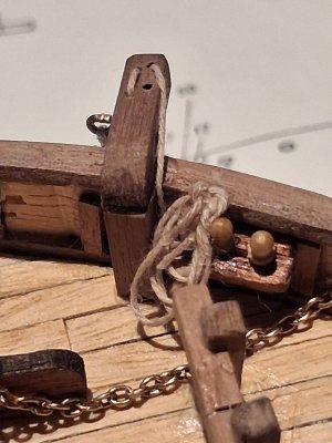
I tried to simulate extra line around the belaying pin which I believe looks fine this is the port anchor davit.

Photo_04.jpg

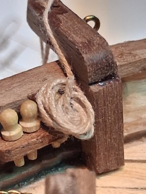
I again tried to simulate extra line around the belaying pin which I believe looks fine, this is the starboard anchor davit.

Photo_05.jpg

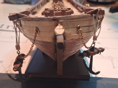
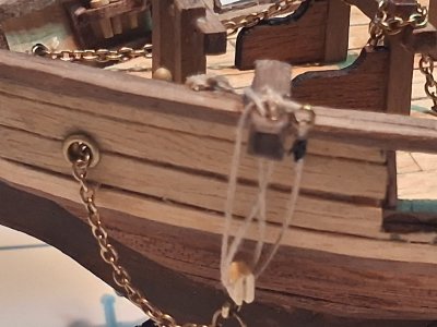
Full on prow view of the hanging anchors looking aft, I think that the uneven length of the block and tackle simulate real life a bit better, all the rum drank would cause irregularities.

Photo_06.jpg
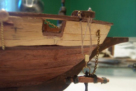
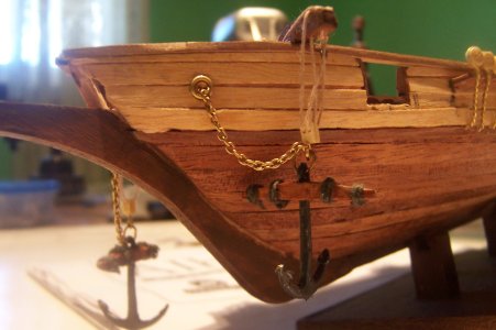
The Starboard block and tackle rigging with the anchor hanging as it would.

Photo_07.JPG

The Port side block and tackle repaired rigging, I missed the second block and tackle hole and went straight to the belaying pin #43), with the anchor hanging as it would.

Photo_08.JPG

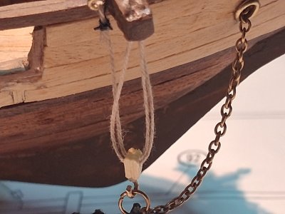
Closeup of the starboard rigging of the anchor davit.

Photo_09.jpg

Closeup of the port rigging of the anchor davit.


Photo_10.jpg
Coming up next: The assembly and installation of the guns and gun carriages onto the model.
Thanks for checking in, until next time.
 
September 29, 2026

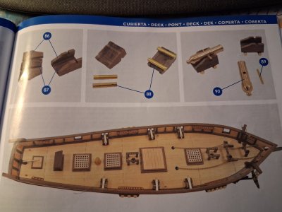
Manual Page 54 of instructions: Assembly and Installation of the six included guns onto the model.

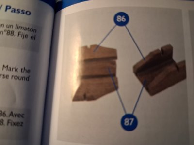
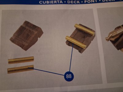
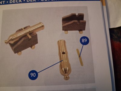
Includes Parts #86 through #90, all in parts pack #2, #6, and #12. Part 86 is precut Gun Carriage sides 12 count from part pack #9. Cut out the gun carriage bases , (Part #87), from 1.5 x 5 x 12 mm from the included Manzonia wood board. Part #88 is the thick 2 mm brass rod of which I cut 12 at 10 mm pieces for the wheels of the carriages. Part #89 consist of the 1 mm brass wire cut to six 10 mm pieces to use for the Gun Shafts; both of these wires were in parts pack #12. Finally Part #90 is the six brass cannon in part pack #9.

First photo are of the full-page manual illustrations for this step, the next three photos are closeups of the four different illustrations.

Photo_01.jpg

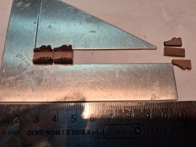
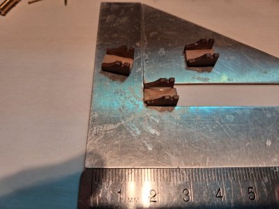
The gun carriage base and sides to make six of them.

Photo_02.jpg

The cut 2 mm wire is to simulate the carriage wheels, unfortunately with the wheels on the guns did NOT fit the model, so off went the wheels, the difference between a model kit that cost just around $100.00 and a better kit costing several hundreds of dollars.

Photo_03.jpg

The guns and gun shafts to be cemented onto the gun carriages for installation onto the model.

Photo_04.jpg


This pictures show two finished carriages and one that is waiting to be glued together.

Photo_05.jpg

The final three gun carriages completed ready to cement the guns and gun shafts in.

Photo_06.jpg

An overhead view of the six cannons installed onto the model’s deck.

Photo_07.jpg

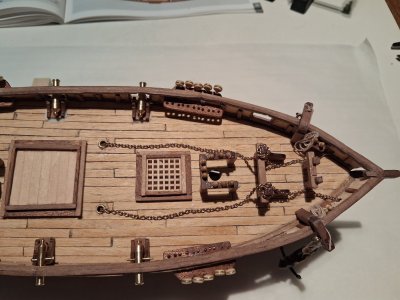
A closeup of the forward main deck with Guns, chains and etc. installed.

Photo_08.jpg

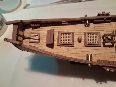
A closeup of the after / leeward main deck with Guns, and furnishings all installed.

Photo_09.jpg


Coming up next, we venture boldly into assembling the Masts and Yards starting with Manual Page 56 of instructions: Assembly and Installation of the Bowsprit onto the model.

Thanks for checking in, until next time.
 
Back
Top