Alvin Clark

straying from the Alvin build a few comments

this is why i consider a "practicum" or build log as only one builders approach to a build and it is not gospel and the way it has to be done.
Now Jim both of us built the dory and followed the instructions which i must say were very thourough it was step by step applied to the dory. However i did stray from wetting the planks and bent them dry, that was my method. rounding out the handles of the oars in the instructions were done by hand, i put the end in a Dremel and at a solw speed setting rounded the handles in a minute.

so what works for me may not work for you or perhaps a tip or how to might work.
 
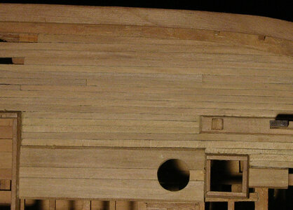
i have read where builders try to bend certain elements of a ship model like trying to bend a caprail edge wise, or the curved cap rail on a stern. Not everything is bent into shape sometimes it is carved to shape as you will now see with the timber for the hawse pipe.

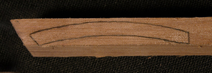
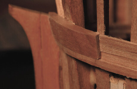
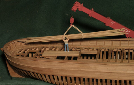
There is no way these heavy planks could be bent to conform to the shape of the bow, so they need to be carved to shape. A piece of wood was cut to the width of the plank and the shape drawn on the top.

Hwood1a.jpg

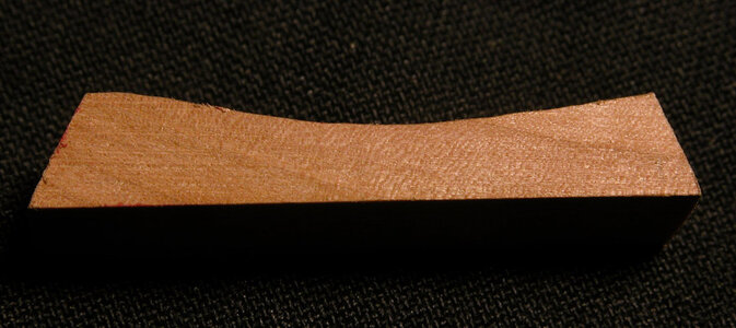
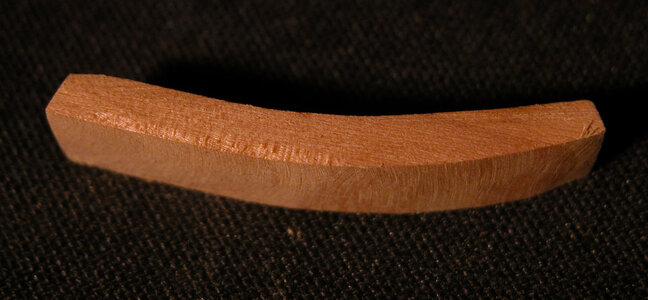
Next the inside was sanded with a Dremel drun sander until it fit the bow timbers. Once the inside shape was established the outer edge was shaped. Thickness and shape of the plank was roughed out then fit to the hull. Its final thickness matched the waterway molding.

Hwood2a.jpgHwood4a.jpg

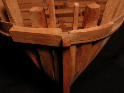
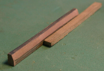
In this photo the piece on the left is fit to the bow timbers. The pieces on the right is being sanded down to match the waterway molding.
What i did was first fit the piece to the hull then shaped it.


DSCN2574a.jpg

What i did was first fit the pieces to the hull then shaped them.

DSCN2576a.jpg
 
Once the heavy plank is in place and sanded to the correct thickness the edges are beveled as shown in the photo of the Alvin.

bevela.jpg

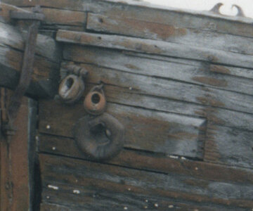
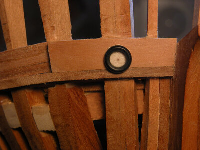
One last step is the drill the hawse hole. Looing at the picture i do not know why the hawse pipe is off center or a wider backing timber was not used but what you see is what was done.

Hwood7a.jpg

Begin with a small pilot hole to be sure your lining up with the hole in the timber behind the heavy plank.

Hwood7a.jpg


the final job on the two thick hawse planks.

Hwood8a.jpg

bow holesa.jpg

Hwood6a.jpg
 
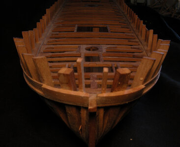
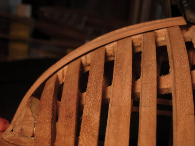
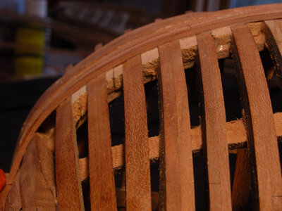
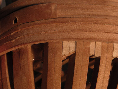
With the heavy planks in place at the bow the rest of the bulwarks can be planked. On this model four strakes of planking were run below the waterway molding. The sides and bottom of the hull are left open to show the framing. At the bow planks do not like to sit flat against the frames, they tend to spring up leaving a gap at the bottom edge. Planks not only have to bend around the bow but also twist to conform to the hull.
sprung plank1a.jpg

A method used to solve this problem is to use bevels and thickness tapers. To begin with the hull is planked in 3 inch thick Oak planks. At 1:48 scale that is .060, the planking has been milled .090 over size to allow for finishing and thickness tapers on the bow planks. If the plank is forced to lay flat against the frame, a gap will accrue between it and the plank above so a thickness taper is used. By using a single edge razor blade or sandpaper the inside face of the plank is shaped so the upper edge is slightly thinner than the bottom edge. Next a bevel is cut along the top edge of the plank.

By doing this it reduces the amount of twist needed to force the plank in place.

If you plan on planking the entire hull you can leave the gap and cover it with the next plank. By doing this a stepping is created and a hollow is left under the bottom of each plank. When the hull is sanded these planks will be paper thin. The thin planks will be affected by changes in humidity and shrink leaving a gap between planks.
Using an edge bevel and thickness taper will not in itself correct the planking so it lays flat to the frame, it only aids in the difficulty of the bow planks to fall in place. Clamping is still needed to force the planks in place.
sprung plank2a.jpgsprung plank3a.jpg

Soaking and steam bending will help bend and twist the planks. By soaking the planks to make them pliable also makes them soft and prone to being crushed and form dimples from the pressure of the clamp. Sometimes these dimples can be sanded out sometimes not.

In the construction of this model once again the planks were not steam bent or soaked in water. They were bent and twisted dry.
That sounds contrary to everything you hear about planking a hull. I have read many times of advice to soak a plank in water and use a hot bending tool. i have used steam bending in extreme cases like heavy wales but most of the time i will bend planks dry. First of all i scratch build models so i can select what wood to use. For planking that has to be bent i select woods that are naturally bendable, close grain and strong. It also has a lot to do with moisture content of the wood. Lumber for indoor use and the wood you get in kits are kiln dried to 6% to 8%. The drier the wood the more brittle it becomes. What i am using is air seasoned wood with a moisture of around 20%. I know what your thinking wood with such a high moisture will shrink and crack and that is true bring in a piece of lumber at 20% into the house at a dry 70 degrees it will indeed crack, warp and shrink. When i plan a project i work up a material list and cut planking first. By the time i get to it the wood has been laying around for a few months. Wood is hygroscopic leave it outdoors and it will accommodate to its surrounding. So wood at around 20% moisture bends much better than dry wood in a kit that might of been sitting a warehouse for months.

i live in a place where temperatures are drastic today it is Fahrenheit 3 Celsius -16 in a few days it will be Fahrenheit 50 Celsius 10
I have models that are 15 to 20 years old and as tight as the day i built them.
 
Last edited:
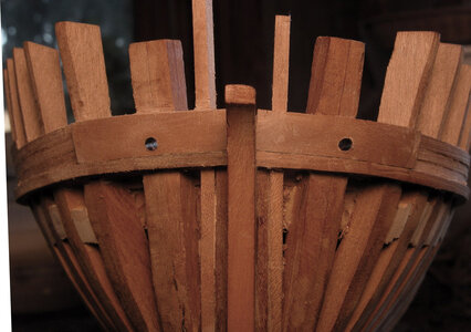
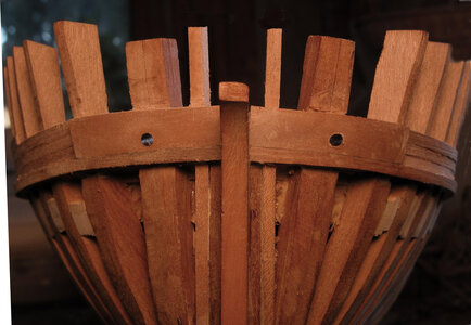
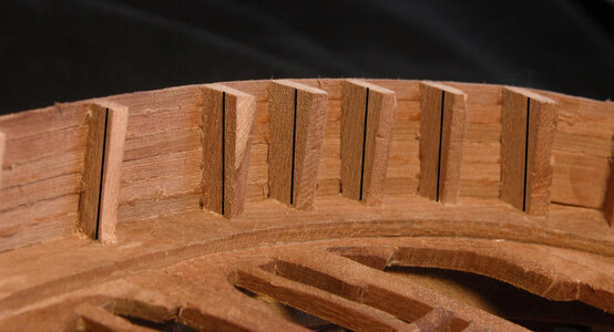
Once the bulwarks are planked up i went back to finish off the stanchions around the hull they have a taper i need to sand in. i left them over size on
the inside because they are beveled and a taper. Here i marked out the inside.

marked to trima.jpg

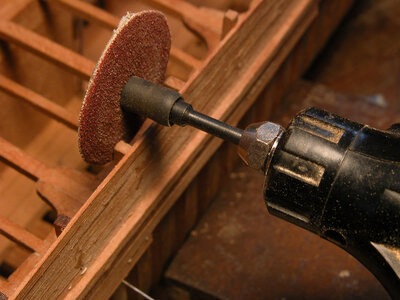
To finish the stanchions i used a disk sander with the sandpaper on the inside of the disk.

dremil insidea.jpg

and that finishes the bulwarks
 
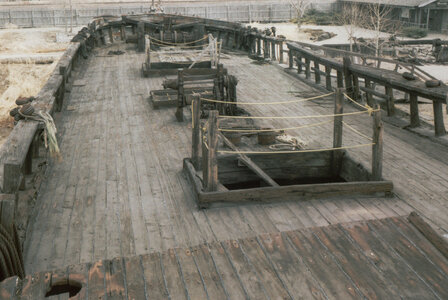
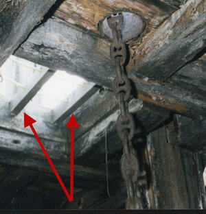
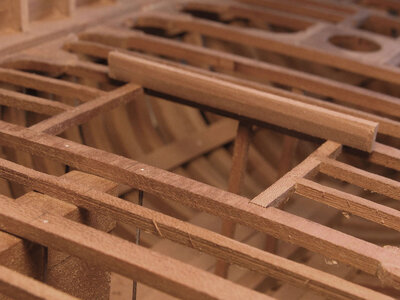
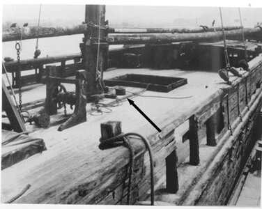
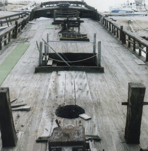
On deck of the Alvin Clark there are three hatches to make coamings for. I have seen model builders plank up to the hatch opening and set the coamings on the planking. Coamings set on the beams and carlings with the deck planking running to the side and not underneath. This can be seen very clear in the second photo.

hatch 1a.jpghatch 2a.jpg

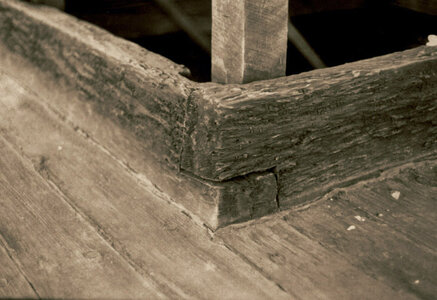
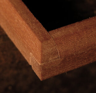
I have seen in build logs where the model builders used 45 degree corners like a picture frame. This type of corner would fall apart. Coamings were always a lap joint.

hatch 3a.jpg

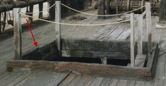
Its hard to see in the photos but the sides of the coamings had a taper from the decking to the top edge. Finally the last feature added to the coaming are the notches shown by the red arrow in the second photo and below. These notches were used to hold strong backs in place the red arrows show two strong backs.

hatch 4a.jpg

The up right corner posts were added when the Alvin Clark was put on public display and were not part of the original ship.
 
Last edited:
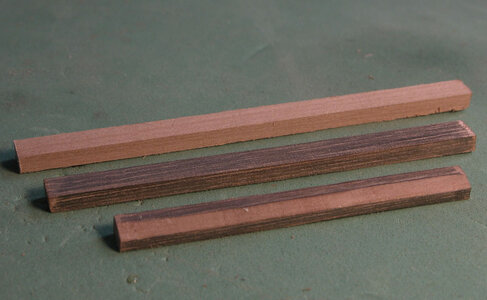
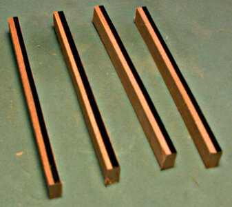
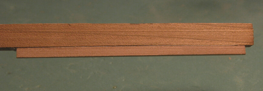
Coamings were 5 x 10 inches so cut the correct size material larger than the longest length you will need. It is difficult to make a bevel without any sort of guild. One trick is to use a pencil and shade the piece. As you shape the bevel you can see the lower and upper edges and you are able to keep them even from one end to the other.

hatch 5a.jpg

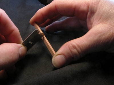
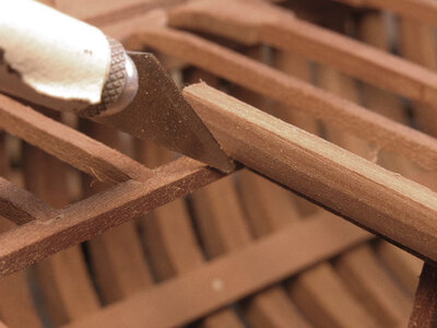
Cutting the bevels by hand can be done quite simply by holding the piece between your fingers and scraping the edge with a single edge razor blade.

hatch 6a.jpg

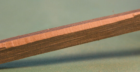
The trick is to keep the shaded edges even all along the piece. Once you are down to size for the bevel a few swipes with a file or piece of sandpaper will even out any unevenness. You can see on the left it a little wavy.

hatch coaming 3a.jpg

The top of the deck planking should run along the bottom edge of the bevel.

hatch coaming 4a.jpg
 
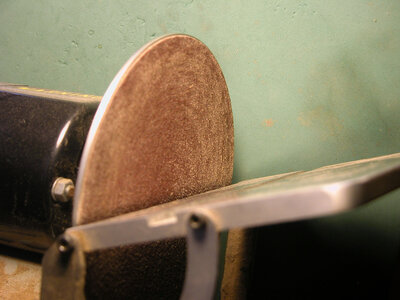
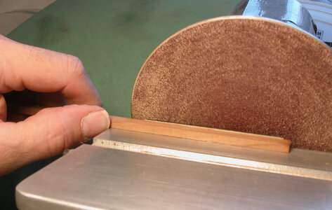
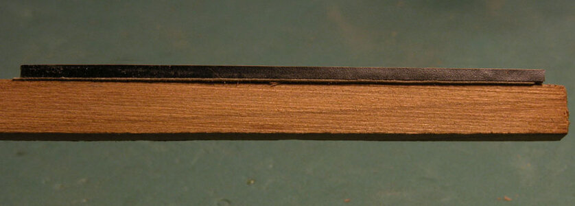
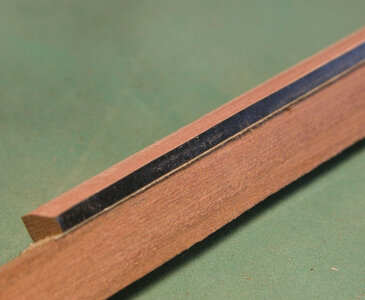
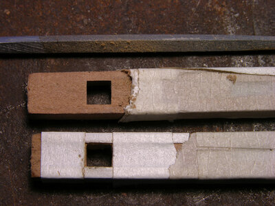
Another method to create the bevels on the hatch coamings is to use a disk sander. First I marked the upper edge by using a strip of electrical tape. Next is to set the table to the angle of the bevel.

hatch coaming 5a.jpghatch coaming 6a.jpg

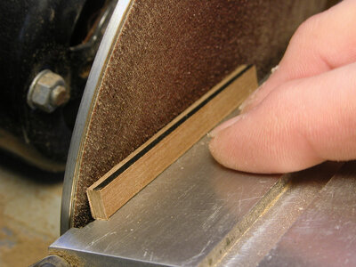
A problem with the small, short pieces is holding them against the sanding disk without sanding the tips of your fingers in the process. A solution to this is use two sided tape and stick the coaming to a larger piece of wood. This give you much better control and saves your finger tips.

hatch coaming 7a.jpghatch coaming 8a.jpg

By holding a larger piece of wood you can gently move the coaming back and forth on the disk to get an even sanding along its length. The idea is to sand the coaming right to the edge of the electrical tape.

hatch coaming 9a.jpg
hatch coaming 10a.jpg

The final pieces will look like the photo.

hatch coaming 11a.jpg
 
Once all the coaming pieces are cut and beveled the next step is to mark them out for length. Marking is always done with the knife by making a small cut line. Cuts are far more accurate than a pencil line.

hatch coaming 12a.jpghatch coaming 13a.jpghatch coaming 14a.jpg
 
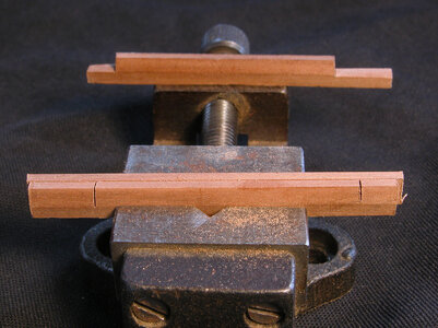
You can either cut both side pieces at once or cut one at a time using the first side to mark the cuts for the second piece. The coaming sitting on the vice is the piece that will sit on the carling, note it has been notched so the beveled top half is cut away and the ends are left long for fitting later.

hatch coaming 16a.jpg

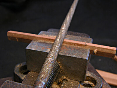
The pieces clamped in the vice are the sides that sit on the beams. These pieces are up side down and the bottom half is being cut for the notches. The bevel line is the guild for the depth of the over lapping notches. Coamings that set on deck beams will need the bottoms shaped to fit the curve of the beam. By using a rounded file a few swipes across the bottom will produce enough to form the needed shape.
hatch coaming 15a.jpg
 
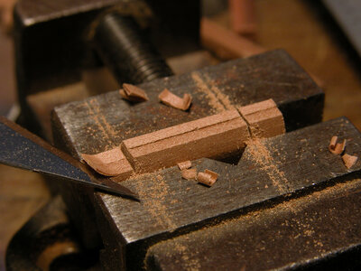
to insure a nice flat even cut the coaming sides are clamped in a vice to the depth of the bevel. A knife is used and the notch is cut down even with the top of the vice.

hatch coaming 18a.jpg

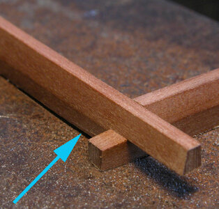
In the photo the blue arrow is pointing the shadow under the coaming indicating the depth of the notch is still to high. Continuing shaving down the notch until both sides sit flat on the surface.

hatch coaming 19a.jpg
 
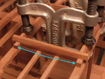
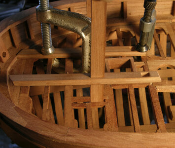
With all the bevels and corner joinery done clamp the two sides on to the carlings so they are even on the inside shown by the blue arrows. Small adjustments might have to be made to the inside edge of the notches until they fit tight between the clamped sides. Once you have a nice fit glue the corner joints.

hatch coaming 17a.jpg

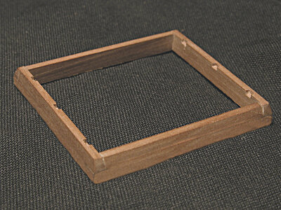
The final hatch coaming should sit perfectly over the hatch opening with the inside of the coamings in line with the beams and carlings with nice tight fitting corner joinery. Lastly cut the notches for the strong backs before gluing the coaming to the deck.

hatch coaming 20a.jpghatch coaming 21a.jpg
 
Running down the center if the deck are heavy planks to help support the windlass, masts, and posts. In the photos you can see the heavy planks, which have a beveled edge. A black arrow is pointing to the heavy planks. The planks ran between the two hatches and from the forward hatch to the samson post at the bow

center planks2a.jpgcenter planks1a.jpg
 
Before placing the heavy timbers a few holes have to cut into them for the posts and windlass supports and one for the mast. Placement of the holes is very critical and they have to match up with the beams and carlings on the deck structure. Holes for the posts are close to the size of the width of the heavy timber so if you’re a little off center it will show up.

framing1a.jpg

the wondlass bracket runs through a hole in the heavy plank and dpwn between the two carlings.

fitting windlass posta.jpg
 
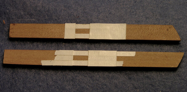
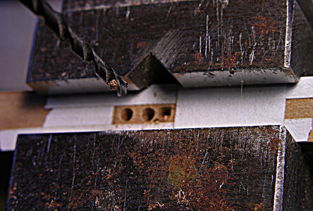
To begin cut two heavy planks to the correct length, shape one end to match up with the waterway. Measure back to the exact location of the windlass brackets. Rather than trying to find center on the plank take the width of the bracket and subtract it from the width of the plank. Half that number is the width of the strips of tape. Simply stick two pieces of tape along the edges of the plank. Using tape gives a absolute edge to cut to, a pencil line does give a sharp edge. Once the holes are taped off next step is to dill starting holes.

taping windlass brace.jpgdrilling windlass bracea.jpg

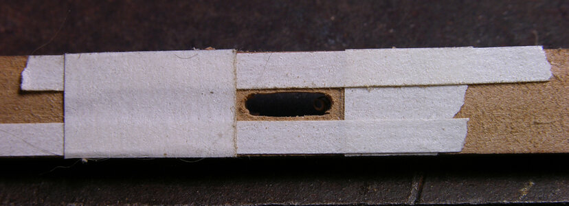
Break out the material between the starter holes. Using a scalpel blade clean out the hole to the edge of the tape.

drilled windlass bracea.jpg

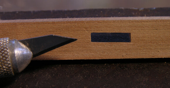
For the windlass brackets the holes were finish cut with the scalpel. Another method is to cut the hole close to the finished size and finish it with a file. Either way works, the objective is to get a clean sharp hole ever so slightly smaller than the post fitting into it.

finished slot1a.jpg

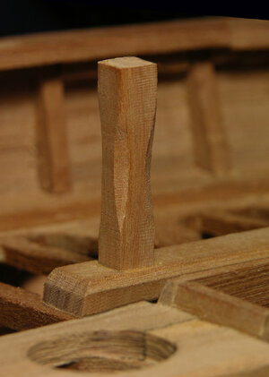
With the post holes finished the corners of the posts are shaped and the post set in place. The posts run through their holes and all the way down to the bottom of the hull.

cutting out post holesa.jpg

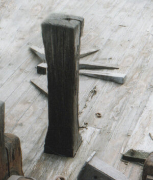
the posts on the Alvin Clark

real post.jpg

the post on the model

model posta.jpg
 
Last edited:
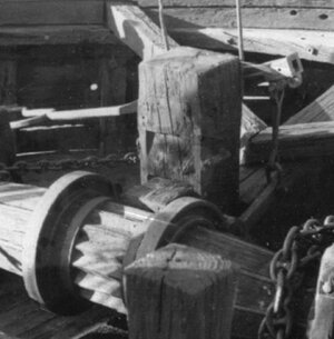
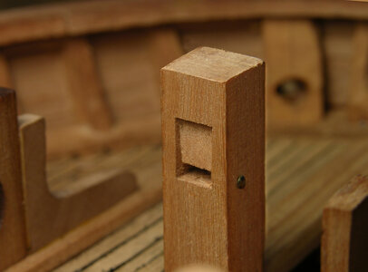
The Samson post runs all the way down to the keelson and sits right in front of the windlass. An inset has to be cut in the Samson post to hold the pawl.

real samson posta.jpg

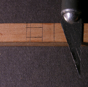
Measure and mark the location for the inset so the pawl rides on the windlass.

samson post1a.jpg

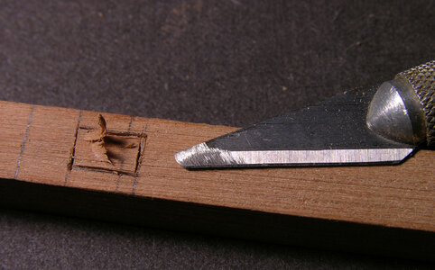
i sarted by stabbing the point of the blade along the lines, then when the tip breaks off i sharpen it into a chisel

samson post2a.jpg

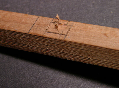
Now using the blade as a chisel i can cut the depth

samson post3a.jpg

finished samson posta.jpg
 
To start the deck planking the first items needed are the planks and caulk. The decking on the Alvin Clark was Pine and averaged between 4 and 6 ½ inches wide.

construction shota.jpgcrayonsa.jpg

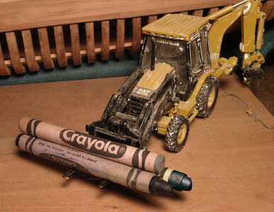
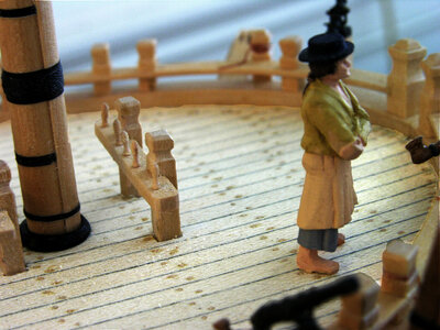
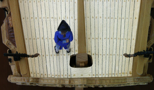
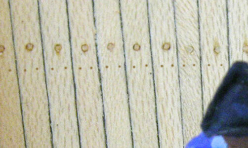
For a time the use of Holly was popular for model ship decking Holly could have been used because of the process of sanding the salt and grime off the decks of navel ships. This process used a soft sandstone and was called “holystoning” which whitened up the deck. The wood Holly seemed to fit the description of “holystone” and the process of whiting up a deck. All the holystoning of a deck is not going to turn a naturally brown colored wood white. Model builders began looking for a more natural colored deck so Holly fell out of favor because Holly is a stark white wood. For caulking the backhoe is bring in a load of crayons. Advantages to the crayons are the slightly sticky wax and the range of colors from light gray to black. Before lying down deck planking we will take a look at the use of fasteners. Most model builders will hold close to scale when building the model but when it comes to the fasteners they are often grossly over scale. Looking at the deck of the Kingfisher model the tree nails stand out due to their over scale. Taking another view of the treenails from directly above once again the tree nails stand out. Figuring scale these fasteners would be 2 inch diameter, which is far to large for deck planks.

kingfisher1a.jpgkingfisher3 scale1a.jpg

Added to the photo are scale fasteners, note they can hardly be seen so lets take a close look. In the large photo the scale fasteners are right under the row left of the figures hat. The actual planking nails on the Alvin Clark had a head of 5/8 of an inch. At a quarter to the foot scale the nails would measure .012 or about 1/164 of an inch. Checking items around the house the closest to scale would be the bristles on the average hair brush at .018.

kingfisher scale2a.jpg

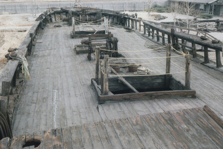
Notice the deck color of the Alvin Clark, it is a silver gray due to the natural oxidation of the woods surface. This color does not penetrate very deep into the wood so during the working days of the vessel the gray color would have worn off from day to day use. If this deck were holystoned the gray would be sanded off and the natural tan color of the deck would show, holystoning would not make the gray turn white like the Holly decking on the Kingfisher model

real decka.jpg

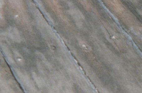
Looking at the deck of the Alvin Clark the caulk seams are barley visible let along the fasteners. Lets take a close look at the nails and you can see they are quite small. The nails were counter sunk and caulking was used to plug the holes. In the art of traditional model ship building the over scale use of fasteners are acceptable. For anyone wanting to try and maintain scale down to the use of fasteners the most practical materials would be plastic rods or sterling silver wire or skip the fasteners.

real deck closeupa.jpg
 
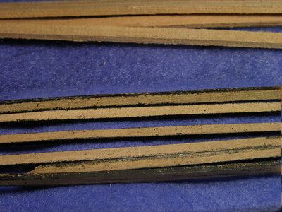
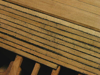
The process of planking the deck begins with taking the planks and coloring the edges with a black crayon. At this stage the planks look quite messy because you do not have to be very careful if you run over the edge with the crayon. The wax crayon does not sink into the wood like paint or glue it just sticks to the surface.

Deck planks on the Alvin Clark were up to 30 feet long so on the model 8 inch long planks are within scale.

caulked planksa.jpgplanking unfinished2a.jpgplanking unfinished1a.jpg
 
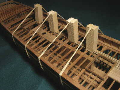
There isn’t much room to use C clamps to hold the planking to the deck beams while the glue sets, the most effective method is to use blocks and rubber bands. By adjusting the rubber band you can lean a block into the edge of a plank and pull it towards the plank next to it.

blockinga.jpg

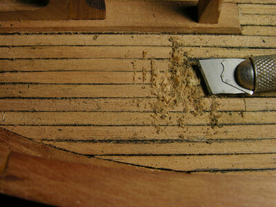
The deck is not sanded but scraped.

Take a single edge razor blade and hold it with pliers and break it into pieces. Pieces of the broken razor blade are then inserted into the handle of an Exact O blade handle.

scrapinga.jpg

Scraping the deck quickly removes any crayon and gives the wood a smooth clean surface. In larger areas a full size single edge razor blade is used to scrape smooth the deck.

final scrapinga.jpg

looking very close at the deck you can see the caulking and it does not stand out like adding black stripes on the deck. It is more of a subtle look so one element does not stand out or appear glaring.

very closea.jpg

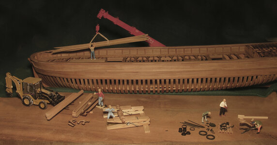
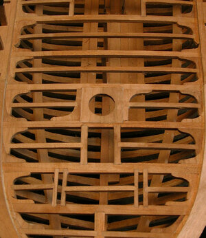
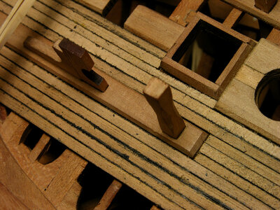
Depending on your choice for the final appearance of the model will determine the amount of decking you apply. On this model it was decided in the beginning to leave as much of the vessels timbering and construction visible. At the bow the deck is planked from center to the waterway giving enough area to effectively showing a planked deck and as the planking extends toward the stern less and less is used to expose the center trunk for the drop keel as well as the lodging knees along the sides. Only a narrow strip is planked on the other side giving the model an airy openness so you can look into the hull.

final deck2a.jpg
 
Last edited:
Back
Top