Alvin Clark

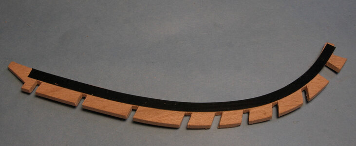
i preped up the first section of the waterway with a piece of electrical tape. Using electrical tape gives me a clear clean line. This line is the depth of the notches.

ww tape.jpg

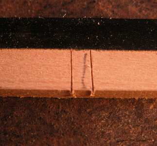
Using the cardboard pattern which has been fit to the hull lay it on a wood blank and mark each notch. Make two cuts along the sides of the notch. Light pressure for the first cuts are better as the knife blade will not be prone to following the grain. Go over the cuts a couple more times to deepen the cuts
notch3a.jpg

With a knife make two angle cuts from inside the notch to the outer cuts. This will create a grove no larger than the rim of a penny. When i cut the notch the saw will follow the V grove and not wonder from side to side.
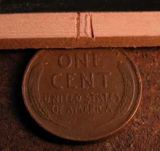
notch4a.jpg

With a fine razor saw cut very lightly and at a steep angle along the V grove. By cutting at a steep angle you are deepening the cut and the saw will follow along the cut .
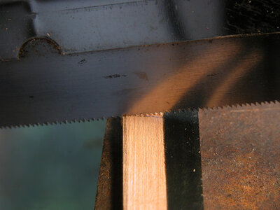
notch5a.jpg

By the time you have made the first saw cut cutting at a 90 degrees has become easy at least 70% of the woods thickness is cut away and the saw will follow the original knife cut much easier. Make the final cut right to the edge of the electrical tape.

notch6a.jpg

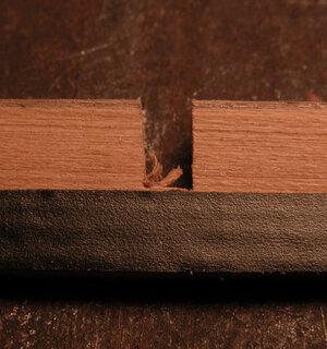
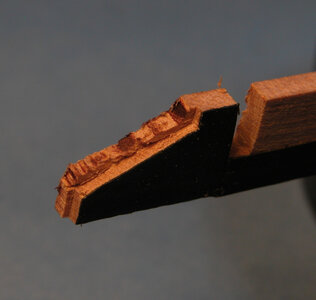
These are the two final cuts. In the photo you can see if the saw cut runs amuck in the cut on the left, it will take the path of least resistance and cut towards the center of the notch. This was the reason for the V grove cut at the beginning. The saw will naturally use the knife cut as a guild. Cutting with a razor saw has to be done very easy and slow to avoid the cut from running off its mark.
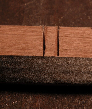
notch7a.jpg
 
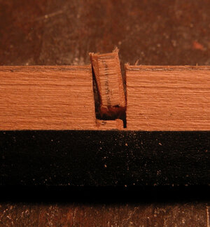
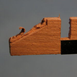
A knife stabbed into the notch will break away the inner piece. Note the break is kept away from the final end of the notch. This is done to avoid any breakage beyond the tape.

notch8a.jpg

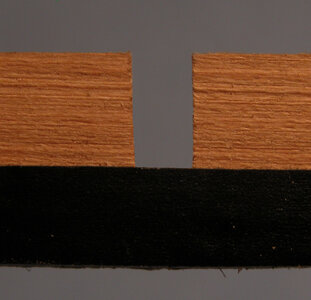
using a sharp knife and trim out the bottom edge until its even with the tape edge. The final notch should be clean, square and crisp.

notch10a.jpgnotch11a.jpg

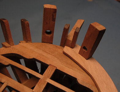
When all 18 notches are cut for the stanchions in the first two waterway sections a notch for the knee and a scarf joint have to be cut in the ends of the waterway section.

waterway joinerya.jpg
 
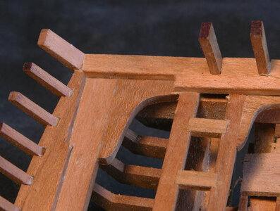
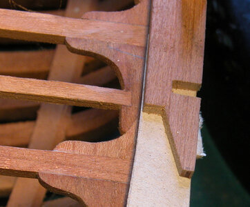
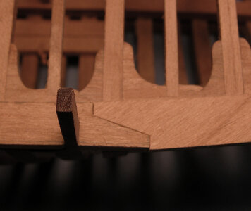
The waterway knee ties the stern waterway to the side waterway. The picture shows clearly how the knee fits into the waterway notch.

knee notcha.jpg


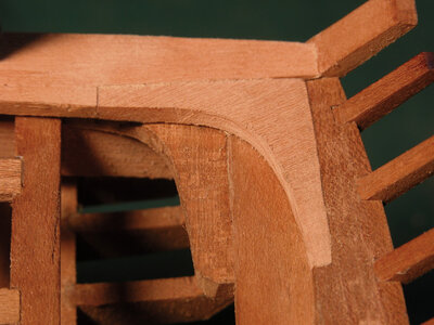
The photo shows the knee in place. Making the knee begins with a cardboard pattern cut to fit the corner notches which the photographer is taking a picture of in the post above.. Once the pattern fits clean and snug it is then copied to a piece of wood.

stern kneea.jpg
 
What is nice about model ship building it is a multi level hobby. You can build a model and skip over fine details and joinery and go for a general over all look of "this is what a ship looks like." For me personally building models is like putting together jig saw puzzles and i did hundreds of them over years, As my mom got older and older i would visit a couple times a week. We would sit at a table and assemble puzzles and talk. The puzzles focused and quited the mind. As an artist and growing up in a family of artists my mnd serches and finds patterns in everything, looking for finer and finer details. Mom passed away 2 years ago at the age of 96.
Anyhow, my way of building may not fit everyone, i might spend a month or two making a part or parts and redoing it until i got it right, or sitting running scenarios of how to do something in my head.
The Alvin Clark project was to build a scale model as close as possible to the real ship. Timber for timber and all the joinery and i will say there is a lot! of joinery and cutting notches.

With that being said i have the stern knee in place and now i have to scarf the other end to the next section of the waterway.
 
Moving on to the next section of the waterway all the stanchion notches are cut and the waterway is fit to the hull. Now the two sections have to be joined together.
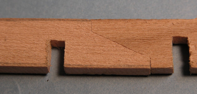
the first half of the scarf is quite easy, it is just a matter of cutting a notch in the end of the waterway.

joint tracing 1.jpg

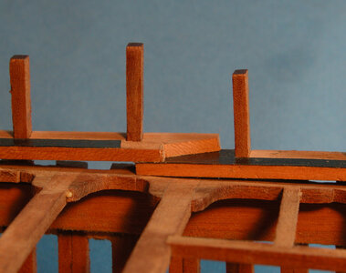
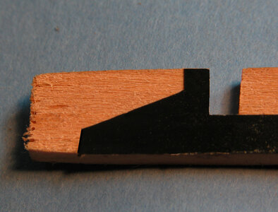
The fun part is cutting the secons half so both match up. Using electrical tape on the end of the waterway lay the second section under the first as shown in the photo. Next use a sharp knife and cut along the scarf tracing the scarf to the end of the second waterway section. Go over the cut several times with a sharp Exacto knife. The first few cuts should be light and as the cut deeper more pressure can be used. Both waterway sections are locked in place by the stanchions so fitting the scarf will have no room to shift into place.

scarf2a.jpg

remove the tape and i used a disk sander on my Dremel and sanded down the end as close as i can get to the tape edge.

scarf3a.jpgscarf4a.jpg

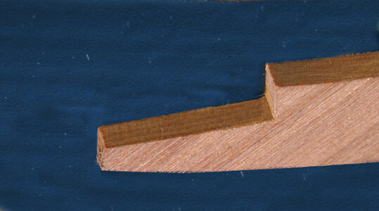
I will use a new sharp blade and cut along the tape edge making light cuts so the cut does not run off and follow the grain. i keep cutting until i hit about a third of the thickness of the piece. Then just hack wawy to remove the extra material.

scarf5a.jpg


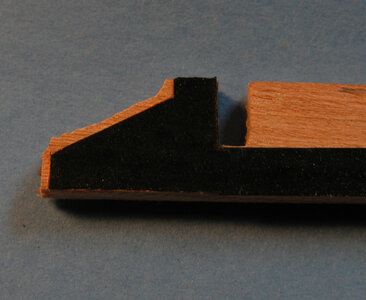
I Remove the remaining material from the scarf by cutting it away with a knife. A trick is to cut the material down to the level of the original cut until there is a faint edge between the first cut and the material that was removed.

scarf6a.jpg


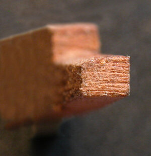
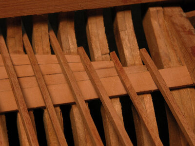
At this point make a slight angle cut from the point where the two areas meet to the back edge of the joint. This will create a slight bevel. Looking at the bevel with macro photography it is very slight and just enough of a back bevel to allow the original two edges of the scarf to meet up exactly.

closeup scarfa.jpg

scarf 7a.jpg
 
what stanchions that were still standing i went ahead then off level with the deck and a waterway was made from scratch.

bow1a.jpg

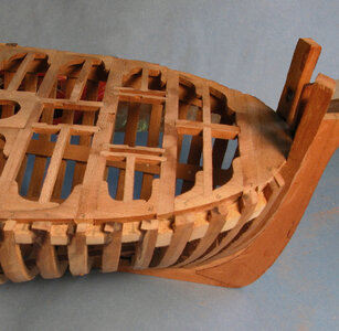
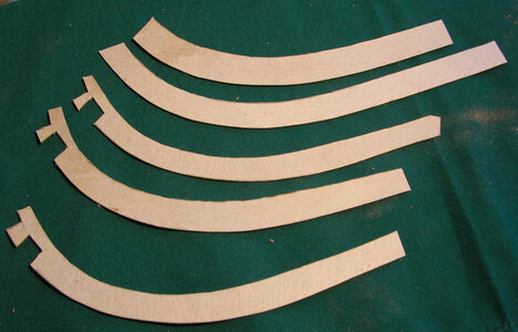
Patience is needed to get the waterways in the bow just right. The photo shows 5 attempts to get the correct curve and fit. To begin you want the waterway to follow the shape of the bow as close as you can get it.

bow2a.jpg

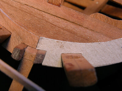
I First cut the notches to fit around the knightheads and hawse timber. Between these timbers the waterway had a dove tail fit.

bow3a.jpg

Slip the other end of the cardboard template under the scarf joint at the end of the last section of waterway. Use a new, sharp Exacto knife and cut out the scarf

bow4a.jpg

The cardboard template should fit nice and snug around the bow timbers and scarf and follow the curve of the bow.

bow5a.jpg

With everything fitting just right i Cut the waterway in wood, first cut the notches at the bow, fit it to the model then cut the scarf.

bow8a.jpgbow9a.jpg
 
Cutting the notches were done last because you don’t want to complete the waterway then try to fit it to the hull. You may find yourself scraping a lot of work if fitting the waterway goes bad. First a strip of electrical tape was cut to the width of the waterway from the end of the notch to the inside edge. The notch locations were traced from the plans. Using a sharp knife a score line was cut into the waterway to mark the sides of each notch. The notches were cut the same way all the others were done.

bow10a.jpg


a view from the underside of the hull, note the oversize of the waterway. The waterway was made a bit wider than the finished size. A little wiggle room is a good idea when fitting such a piece. Later when the hull gets its final sanding the waterway will fit flush with the hull. A reason for marking the inside dimension from the end of the notch to the inside edge of the waterway exact with electrical tape is because once the waterway is glued to the hull it is almost impossible to sand the inner edge. The outer edges is no problem so it was left a little larger.

under waterwaya.jpg

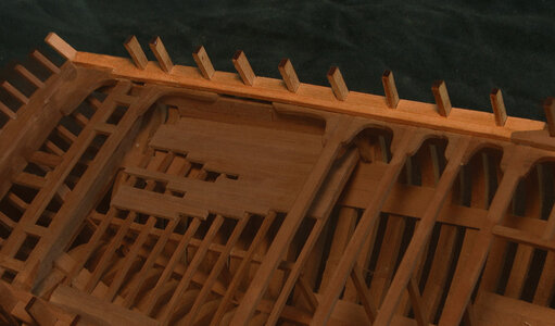
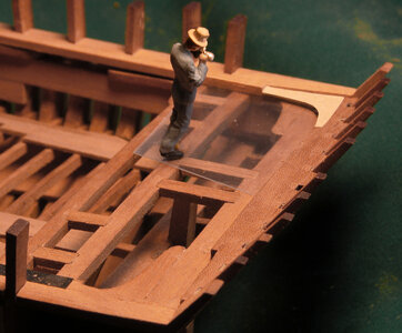
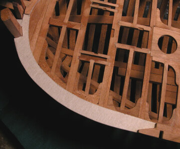
and we now have all the waterways on the model.

two waterways bowa.jpg
 
standing in the hull taking a picture

photo shota.jpg

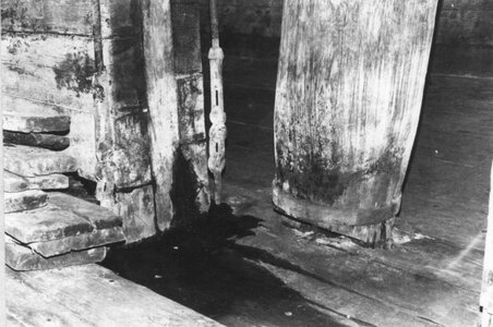
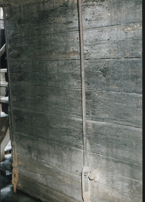
in the actual Alvin Clark its a picture of the end of the centerboard trunk.

photo 4a.jpg

Why did the phrotographer take this picture? to get a shot of the turn buckles. Next to the turnbuckle is the iron rod and bolt that runs through the trunk and centerboard. The centerboard pivits on this rod.

photo 3a.jpg

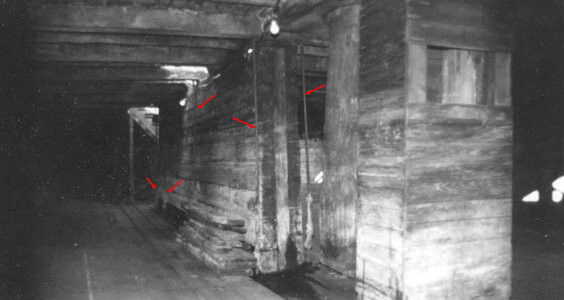
The Alvin Clark had four iron rods and turnbuckles which ran on either side of the center board trunk. The rod ran down rough the deck beam with a washer and bolt counter sunk in the top face of the beam. The bottom end has a turnbuckle linked to an eye bolt in the keelson.

The photo to the right you can see three of the rods and turnbuckles. The rods were spaces unevenly along the trunk. 2 were close together at the front one about mid way and the last was right on the end. The red arrows in the photo below show the position of all four. The two close together is where the crnterboard pivits so i am thinking that is where the stress was.

photo1a.jpg

you can see them from another angle

photo 2a.jpg


well ok then looks like a few turn buckles will b needed
 
Last edited:
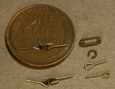
searching the model railroad supply shops i found the right scale turnbuckle and looking through jewelry supplies i found the rest of the pieces, so with all the parts lets make turnbuckles

TB1a.jpg
 
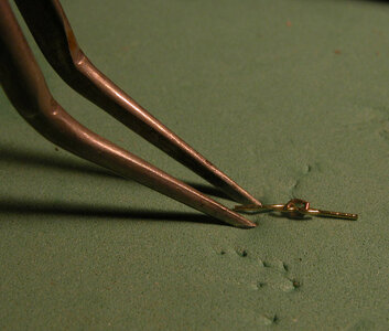
These turnbuckles are quite small and tend to fly away when you try to pick them up. I use a pad available in garden centers that are used to kneel on. The spongy pad allows tweezers to sink in and grab the parts without them flying off in to never never land.

TB9a.jpg

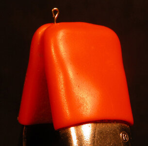
To solve the problem of actually having to hold the parts while they are worked on is solved by using spring clamps.

TB2a.jpg

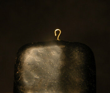
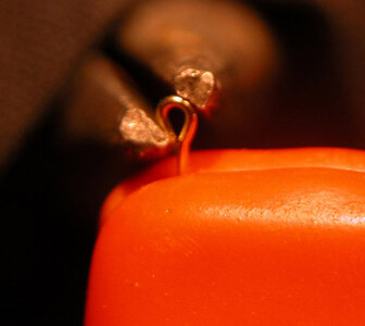
To solve the problem of actually having to hold the parts while they are worked on is solved by using spring clamps. We will now go through the making of a turnbuckle step by step. Notice the eye bolts in the photo with the penny. There is a gap in the eye that needs to be closed in eight of the eye bolts
Use a set of needle nose pliers and give the eye a gentle squeeze until the gap is closed. We are doing this so the link will not slip out.

TB3a.jpg


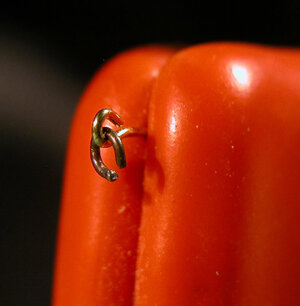
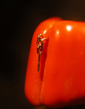
Next step is to add the link ring to the eye bolt. You are looking at super macro close up photos. Looking back at the penny photo you can get an idea how small the parts are. It may be best to assemble the turnbuckles under a magnifying glass.

TB4a.jpg

Run the link through the eye bolt and squeeze the link together, it is easy to crush the ring so easy does it.

TB5a.jpg

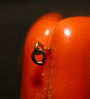
The next step is to open the eye of another eye bolt uding a tapered dentist tool then hook it to the link. Squeeze the second eye bolt shut and this will complete the linkage

TB6a.jpgTB7a.jpgTB8a.jpg

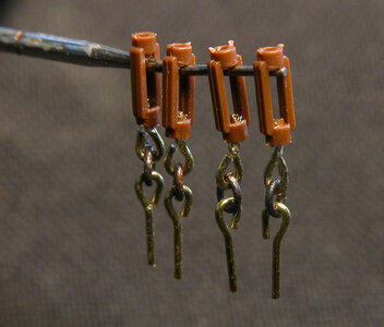
Finally glue the linkage into the turnbuckles.

TB10a.jpg
 
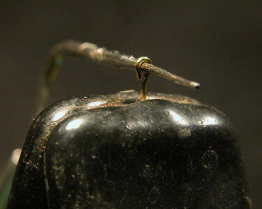
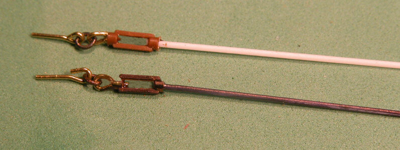
Use a styrene rod and glue it to the other end of the turnbuckles. I used a black marking pen to darken the rod and turnbuckle assembly. Paint is to thick and its difficult to get the variation in the color. A marking pen gives the piece a more realistic appearance.

TB11a.jpg
 
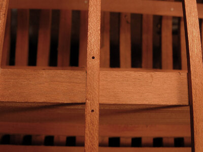
I did not glue in the beams that ran over the centerboard trunk do i could remove them in order to install the turnbuckles. The turnbuckles run through the beams at the ends of the centerboard trunk and two of the beams running over the trunk. I drilled holesthrough the beams on either side of the centerboard trunk.

TBP1a.jpg

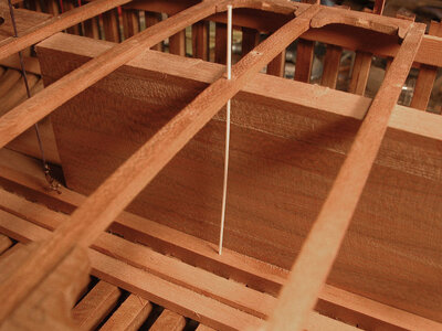
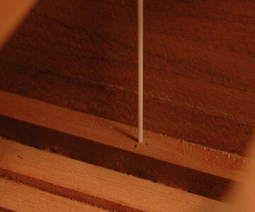
I ran a rod through the beam and to the keelson. Mark the location of the end of the rod

TBP2a.jpg
TBP3a.jpg

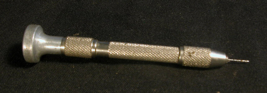
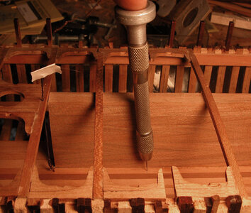
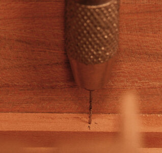
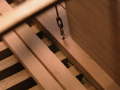
Drilling the holes in the keelson for the turnbuckles is done with a small finger twist drill because it is to tight to get a Dremel tool below deck.

TBP5a.jpg

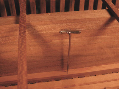
By using a T pin make a starter hole so the drill does not wonder.

TBP4a.jpg

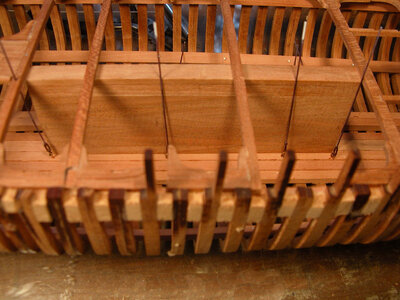
You need only a very small shallow hole to set the eye bolt in place. You can see in the photo below once the rod end has been marked on the keelson the beam is removed in order to drill

TBP6a.jpgTBP7a.jpg
 
Once all the holes are drilled through the deck beams and in the keelson, glue the turnbuckle assemblies into their locations. The deck beam with the mast partner was glued in place before the turnbuckles were added. The plastic rods are flexible enough they could be bent and threaded up through the hole in the deck beam. When gluing the turnbuckles in place i had to make sure not to get any glue on the eye bolts and linkage because they have to be pulled tight.

TBP10a.jpg

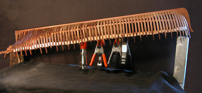
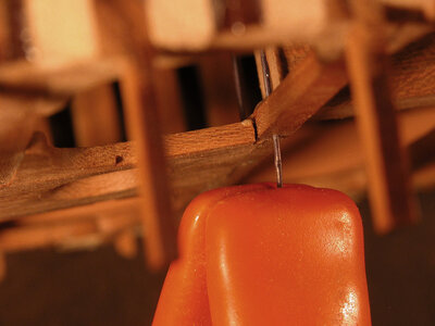
The linkage will sag if the assemble is not pulled tight. The solution I found was to prop the hull up side down. By using spring clamps grab the ends of the rods and the weight of the clamp will pull the linkage straight.

TBP11a.jpg
 
Looking very close under the hull you can see the clamp on the end of the rod.

TBP12a.jpg

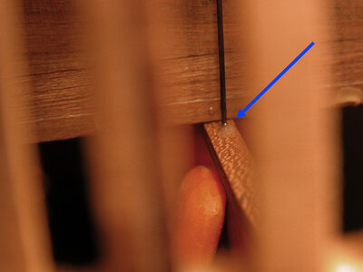
. The blue arrow is pointing to a little dab of glue applied to the under side of the deck beam to hold the rod in place.

TBP13a.jpg

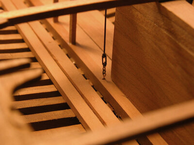
Looking at the turnbuckle assemble you can see the eye bolts and link are pulled tight and stand up straight.

TBP14a.jpgTBP16a.jpg

With all the turnbuckle assemblies in place thread the deck beams down on to the rods and glue them in place. The final step is to nip off the rods flush with the deck beams.

TBP15a.jpg
 
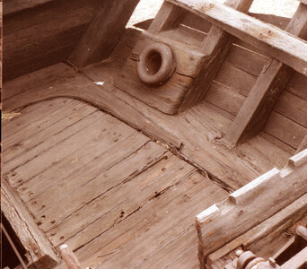
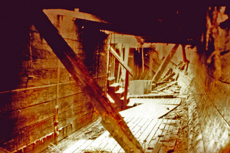
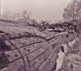
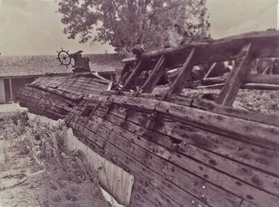
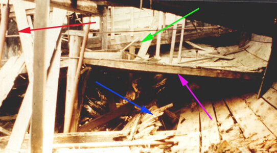
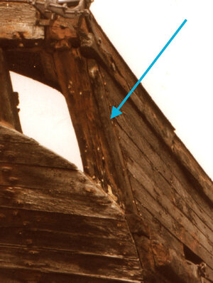
The post above is of the last days of the Alvin Clark just before it was bulldozed and taken to a landfill. The proto below is the condition of the cabin when i surveyed the wreck. It was caving in but i could still go below deck. This is what i found, looking aft at the cabin floor. Starting with the blue arrow you can see where the frames have broken away from the ends of the floor timbers. This resulted in the sides of the hull falling outward and the cabin floor pulling away from the sides of the hull and collapsing into the hold. The green arrow points to the deck beam at the stern deck, which also fell in when the sides fell outward. The magenta arrow shows the floor joist of the cabin floor. The only indication of a wall between the cabin and the hold can be seen being pointed to by the red arrow. There are a few boards still remaining. To the right is a close up of the area being pointed to by the red arrow.

A18 copya.jpg
 
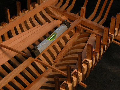
Starting with a floor joist sitting across the bilge stringer a level is place from this joist to the forward one and the floor is set level. Leveling the floor was done before the ceiling planking show in the photo was installed. Use a small spring clamp and clamp the forward floor joist to the frame.

cabin1a.jpg

Cutting the ceiling planking is a tricky job and each piece has to be cut with a taper. The planks at the stern are stepped to avoid the ends from coming to a sharp point. On the actual Alvin Clark the ceiling planking was done a little sloppy and “soles” were added to the bottom of the ends of the floor joists to raise them up and keep the floor level. On the model I strayed from the actual construction used and did a proper job of setting the cabin floor.

cabin2a.jpg

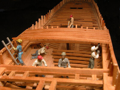
The final ceiling plank is cut on a taper to allow the first seven floor joists to set level. The joists fall in the space between the framing. In this model only enough ceiling planking was used to support the cabin floor. This keeps the hull open and gives a view inside the hull.

cabin4a.jpgcabin5a.jpg

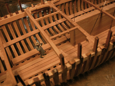
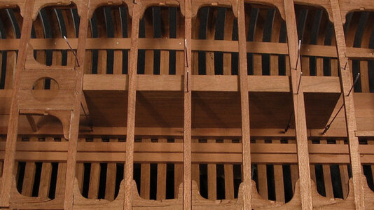
Running down the center under the floor joists a supporting timber sitting on stanchions was used to support the floor. With the cabin floor in place the forward and aft deck beams were set in place and the large knees were installed.

under deck1a.jpg

Only an indication of floor planking was used in order to keep the model open so the structure can be seen.

cabin7a.jpg
 
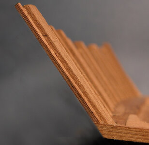
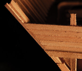
After the cabin floor is installed the next step is to build up the bulwarks, which also serves as the sides of the cabin. This is a straightforward job; the only caution is to be sure the stanchions are all in line so there is no wave in the side of the hull. I gave the stanchions a sanding using sand paper on a block. Before installing the planking a molding is places on the outer side of the corner stern frame. This is done to cover the end grain of the planking and caulking is used between the molding and the ends of the planks to prevent rot.

actual moldinga.jpgside molding1a.jpgside moldinga.jpg
 
Back
Top