Alvin Clark

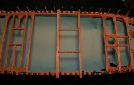
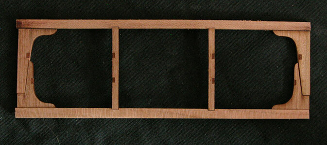
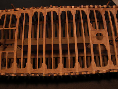
Between the forward section of the deck and the back section is the main hatch. Constructing the beams and carlings that make up the forward hatch is a simple straight forward operation.

forward hatch2a.jpg

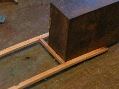
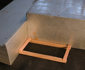
i built the main hatch section off the hull, first taking measurement off the drawings i cut the carlings to length. Next was to use a square block and glue in the carlings.

forward hatch1a.jpg

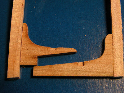
with the structure square i can now fit in the knees. these knees overlap each other

forward hatch3a.jpg

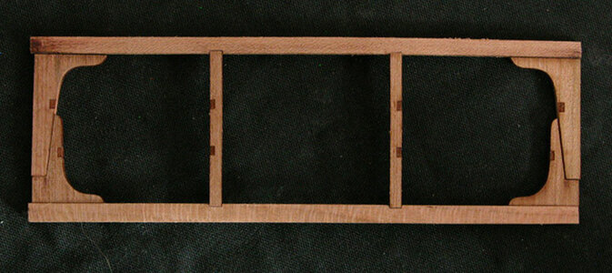
the finished structure can now be set into the hull.

hatch1a.jpg

hatch1a.jpg
 
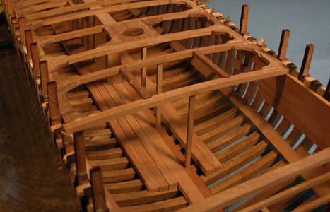
The way i approached building the deck is in sections so the masts, hatches and windlass all are in the correct locations now i have to fill in the darker sections. Here being a little off with the locations of the beams will not affect anything, they are more like filler beams. Also keep the deck open allows room to work below deck.

deck layouta.jpg
 
before closing up the deck with ledges there are a couple details to add to the hold.
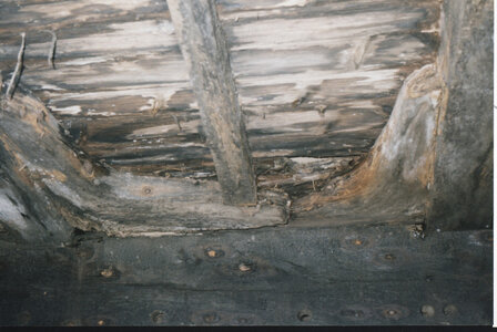
Under every deck beam was a post to support the deck at the center. Also the cabin floor was supported in the center by a 5 x 5 beam sitting on two posts.

beam stantionsa.jpgcabin bracinga.jpg

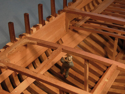
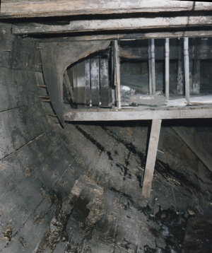
If you were down in the hull taking a picture

cabin kneea.jpg

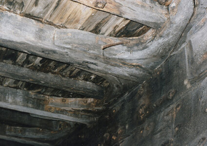
you would be taking a picture of the only 2 hanging knees in the Alvin Clark. A war ship would have such a knee at every beam to support the weight of the guns on deck. In the Alvin Clark a set of knees were at the front edge of the cabin. The beam above the kneee is the forward wall of the cabin

cabin knee photoa.jpg
 
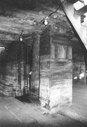
the last structure to add to the hold is this, my wife said it was nice of the builders to include a out house for crew privacy when nature calls.

sorry to say creature comfort was not a priority this is a pump well to protect the bildge pumps from damage when loading and unloading cargo

pump well photoa.jpg
 
Last edited:
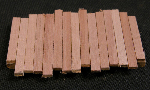
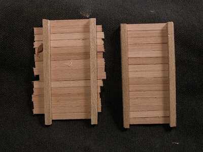
The pump well is a simple box to make. Start with four side frame posts all cut to the same length. Cut four siding boards to the same length. Take two frame pieces and two side boards and square them up and glue them together. Next step is to fill in between the two end side boards. You can pre cut them all to the proper length or glue down random lengths.

pump well1a.jpg

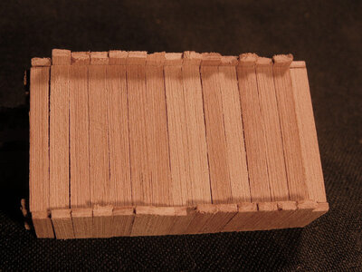
If you glued down random lengths take the piece and sand it on a disk sander. After you have the front and back panels made cut four side boards and glue the front and back panels together. You can see in the photo below the four board cut to the correct lengths at the top and bottom of the sides.

pump well2a.jpgpump well3a.jpg

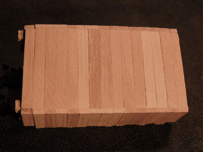
In the final step sand the sides flush with the front and back.

pump well4a.jpgpump well5a.jpg
 
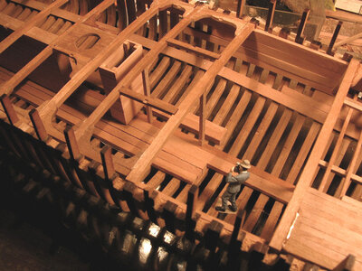
Time to close up the deck structure

deck layout 1Aa.jpg

Starting the deck, the locations for the masts, hatches and the windlass braces are set in place. In the photo below the remaining deck beams ( in red ) are set in place. Exact location is not as critical as placing the beams in the above photo. Next all the ledges ( in yellow ) are set into the deck.

deck layout 2Aa.jpg

after hours of work the deck is complete

fullledges2a.jpg
 
wait a minute lets go back and talk about ledges
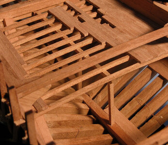
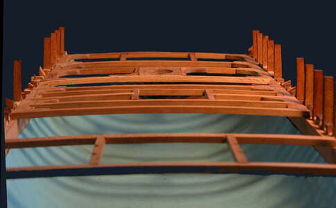
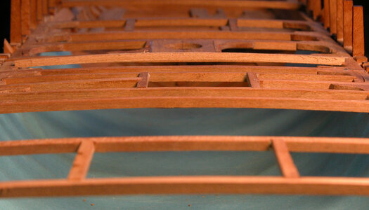
Deck beams arch up at the center which is called the camber. When installing the ledges the camber of the deck beams has to be matched. There are two way to accomplish the camber of the ledges, first is to cut camber into the ledges as was done with the deck beams or spring the ledges in place. In the photo you can see the arch of the deck.
ledges 2a.jpg

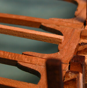
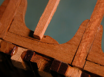
To spring the ledges in place insert one end of the ledge into the notch at the knee then cut the ledge oversize. When both ends are placed in the notches the ledge will spring up.

ledges 4a.jpg
ledges 3a.jpg

the length you cut the ledge will determine the arch keep adjusting the length ubtil the ledges match the deck beams. I doubt this was done in real ship building bending a beam like a ledge would take some force. but maybe it could have been done.
it worked in model building!

ledges 5a.jpg

ledges1a.jpg

knees and ledges on the Alvin Clark

kneesa.jpgledge photoa.jpg
 
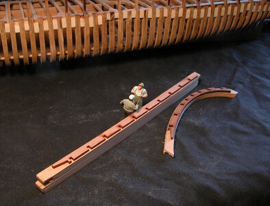
I have to say I love how you create little vignettes with figures in your photos, really brings the model building process to life. I like how you also pose the little camera guy to frame the "real" photos of the ship... Nice.
 
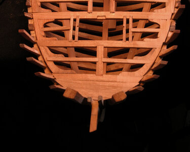
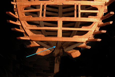
The final piece at the bow is the breasthook. This piece has to be hand made to fit the exact shape of the bow timbers. The blue arrow points to the area of the breasthook. Begin by making a cardboard pattern, the transferring the shape to a piece of wood. Fitting the breasthook will take a little shaping and fitting. You don’t need an exact snug fit against the bow timbers as this will be covered by the waterway.
bow1a.jpgbow2a.jpgbow3a.jpgbow4a.jpg
 
I have to say I love how you create little vignettes with figures in your photos, really brings the model building process to life. I like how you also pose the little camera guy to frame the "real" photos of the ship... Nice.

Thank you there are more little people coming now that the cat stopped taking them.
 
After building the deck there were a lot of notches and knees to cut and fit so before i move on with the build here is a little how to

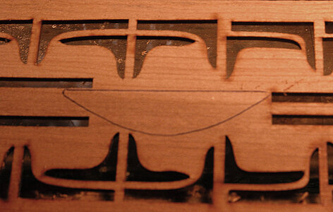
i laser cut generic knees shapes and took those shapes and worked them into the deck structure. To begin it is best to hold the knees in a spring clamp or small vise while they are being cleaned of the laser char and shaped. I will use a round file, a half round and an exacto knife as a final scraping to do the job. It depends on the curve of the knee being cleaned as to which tool I will use.
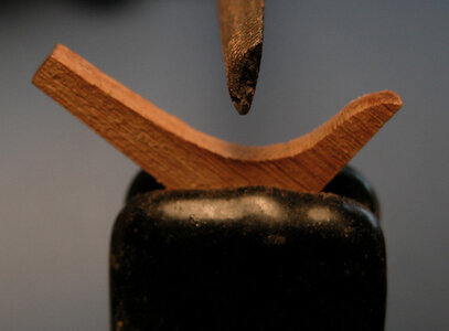
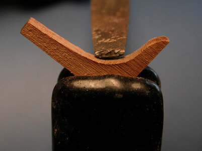
nk1a.jpgnk2a.jpg

when i did the drawings and layed out the deck i laser etched the location of the ledge notches. all i needed to do was to cut them to the proper depth. There is a simple 7 cut method of cutting notches. Once you cut a few they become quite easy to do, the model has a lot to do and you will become proficient in no time at all.

Cuts one and two can be done either with a single edge razor blade or a blunt pointed Exacto knife. After cutting enough notches you will end up with the tips of Exacto blades broken off, save these they make great scrapers and for making blind cuts. Make the end cuts by pressing down on the knife until the cut is about half way down the thickness of the knee. If you don’t cut to the half way point, don’t worry, you can go back and trim the cut deeper.
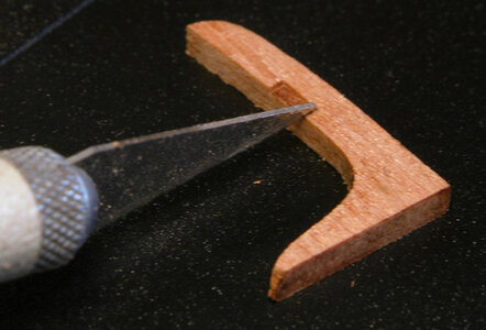
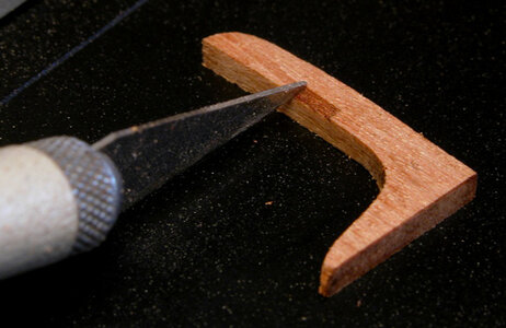
nk3a.jpgnk4a.jpg

Cuts three and four are stabbing cuts made from the corners to the center of the notch. Here is where you end up breaking blade tips and collecting blunt ended blades for other uses. There is no need to “cut” along the back edge; by just stabbing the blade into the notch you will have enough of a cut.
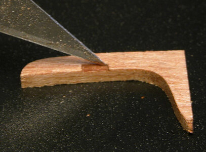
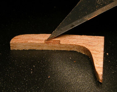
nk5a.jpgnk6a.jpg


Cuts five and six start at the center of the notch and cut downward to the side of the notch. For the first few notches it is better to take a couple shallow cuts rather than trying to make one deep cut. You may end up chipping the corners off.
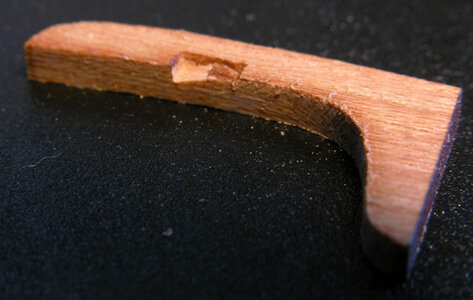
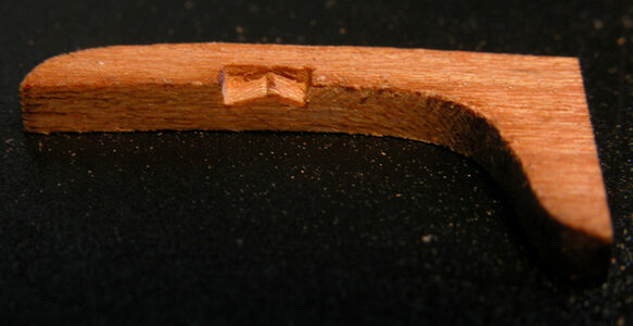
nk7a.jpgnk8a.jpg

The final seventh cut is a vertical cut from corner to corner. This cut goes along the grain and is quite easy to do. The idea is to cut out the triangle piece left from cuts five and six. As a precaution you might want to take a cut along the back of the notch before you make the final vertical cut.
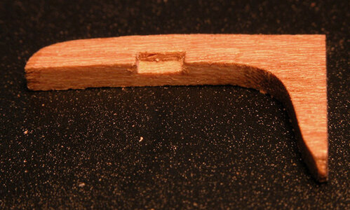
A little trimming or clean up of the notch may be necessary. Once you get the hang of it you can make clean notches in a matter of a minute or two.
nk9a.jpg

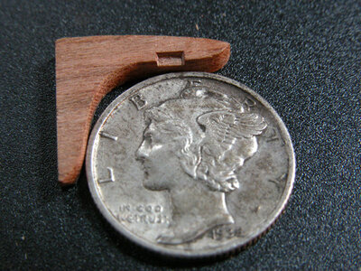
the knees and notches are small even at 1:48 scale
dimea.jpg
 
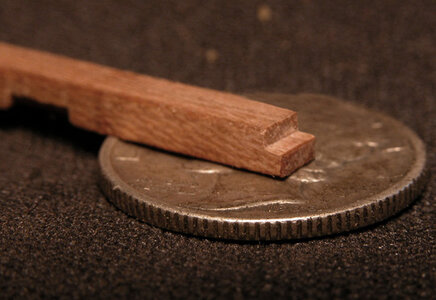
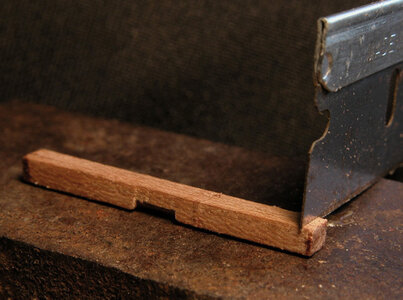
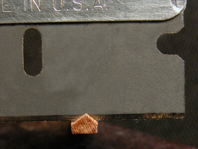
The notches on the ends of carlings, ledges and in the knees are very small as you can see in the photo, their depth is about the thickness of a dime. These notches require little effort in cutting and are done in five cuts.
notch1a.jpg

Before we make the notch slide the piece into the notch it will fit into. Mark the end of the carling with a prick mark from the point of an Exacto blade. In the photo you are looking at the underside of the deck beam with the notch facing the table surface.

notch2a.jpg

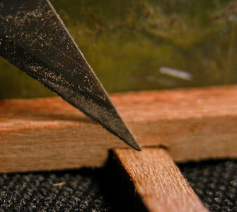
The first cut is the at the prick mark made with the carling end placed in the notch. I use single edge razor blades because they are very sharp and they make a clean cut. The photo shows the cut being done at the end of the blade, actually make the cut from the center of the blade. Doing this allows you to rock the blade back and forth making a deeper cut at the edges.

notch3a.jpg

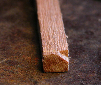
Cut two will nip off one corner, you can see the reason for rocking the blade from side to side on the first cut. The center will be shallow while the edge is much deeper.

notch4aq.jpg

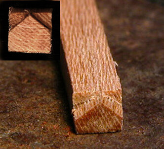
Cut number three is nipping off the other corner so you end up with the end of the carling looking like the insert in the photo to the top right.

notch5a.jpg

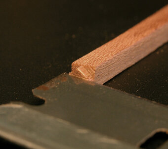
Cut number four is a horizontal cut done to cut off the triangle left from cutting off the corners. The fifth cut is cutting down along the back of the notch. You may find it easier to cut the tip off the triangle then cut a little deeper with the fifth cut then cut a little more of the fourth cut. Basically alternate back and forth between these two cuts until you get a clean notch to the depth you want it.

notch7a.jpgnotch6a.jpg
 
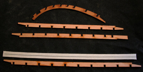
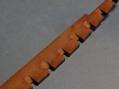
i laser cut a set of waterways and used them to hold the frames in place while the hull was being built like a floating jig, this worked fine for that purpose, however the waterways had to be removed in order to construct the deck. When the deck clamps are in place there is no way to install the deck beams and knees between the waterway and the deck clamps. Removing the waterways after the hull framing was complete resulted in a number of the bulkward stanchions breaking off and i broke sections of the waterways. I could use the laser and recut a new set but after a discussion with myself it was decided to do the waterways from scratch and by hand. There is a lot of notches to cut along with joinery which is a good opportunity to develope on hand skills.

waterway0a.jpg
 
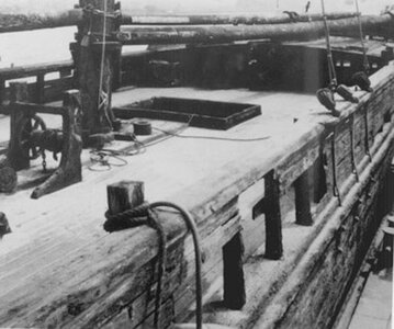
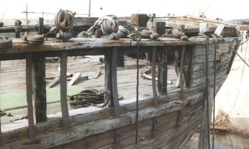
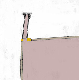
The waterway was a major timber that measured 15 inches wide and 4 ½ inches thick running from the bow to the stern along the top side of the hull.

waterway02a.jpg

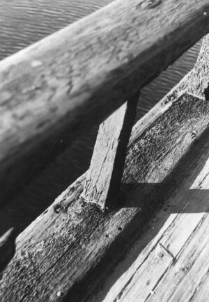
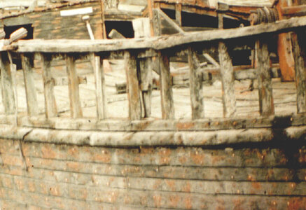
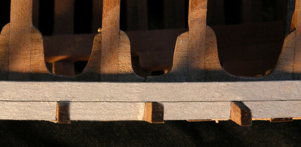
Notches were cut along the outer edge to accommodate each stanchion. On the outer edge was a separate molding piece.

waterway01a.jpg

Here you can see the waterway and the outer molding piece running along the top edge of the sheer moldong.

alvin 15a.jpg

In the photo below you can see the nails were the molding is nailed to the edge of the waterway.

A04a.jpg
 
by the time i removed the waterways and handling the model i broke off a lot of the stanchions. Some buiders will build a model in a jig or mounted to a table, i build models in my lap i handle them a lot and as a result breakage does happen. It might be a good thing because not only do you teach yourself how to buid a model but also how to take one apart and repair damage.

stanchion1A.jpg
 
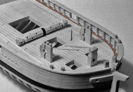
Model ship kits usually do not use a full waterway, they simulate the waterway by using a strip of wood run along the inner bulwark planking and the deck. like the yellow piece. and a molding run on the outside of the hull.

ww2.jpg

when the inside of the bulkwards are open you see the entire width of the waterway and you have a lot of notches to cut.

han ww.jpg

the easier way is to layout the waterways in CAD and laser cut them but the problem with that is very few model builders have a laser cutter in their shop. So you have to make a blank pattern and start cutting notches by hand.

ww1.jpg
 
Last edited:
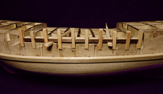
there are two ways to go with building the bulwarks one is like i did with the Sultans and set the waterways in place and inserted the stanchions. If you are slightly off in the location of a notch so whatthe stanchion fits.

bulwark1.jpg


but what if your building a framed hull and the stanchions are the top timbers of the frames. Now you have to cut the waterway to fit the hull and stanchions. That is what i did in part with the Alvin Clark i had to cut the waterway to fit around the stanchions and at the bow i did it like the Sultana. Looking back on the build i could have cut all the bulkward stanchions flat to the deck level and build it up from there. But i did it the hard way
 
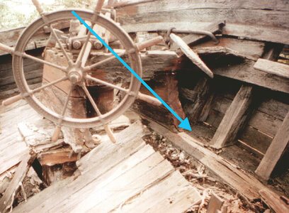
Installing the waterways i started at the stern. The blue arrow in the photo shows the actual waterway.

A08a.jpg.

By the time this photo was taken the Alvin Clark began to cave in on itself. The stern deck has collapsed into the cabin below breaking away from the waterway.

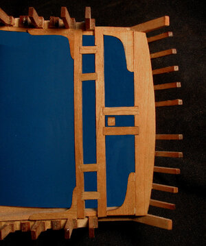
Looking down on the tiller deck before the waterway is installed across the stern

stern ww1a.jpg

The first step to install the stern section of the waterway is to create a cardboard pattern and use the pattern to cut out the waterway. The underside of the notches are beveled to fit tight to the stern timbers.

stern ww2a.jpg

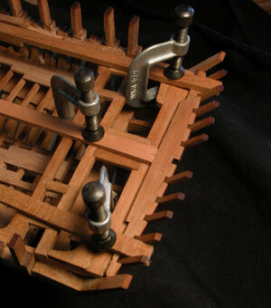
The tiller deck has a slight arch to it so the ends are clamped by using a plank and clamped to the deck knee. The center plank pushed the waterway notches into the stern timbers.

stern ww3qa.jpg
 
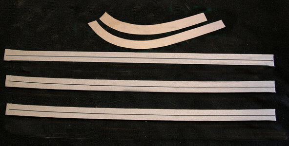
cardboard patterns are made of the waterway all along the hull. The line running down the pattern is the inside face of the stanchions

patterns.jpg

i wanted to keep the same measurement from the inside of the stanchions to the inner edge of the waterway

fitting1a.jpgfitting3a.jpg
 
Back
Top