Alvin Clark

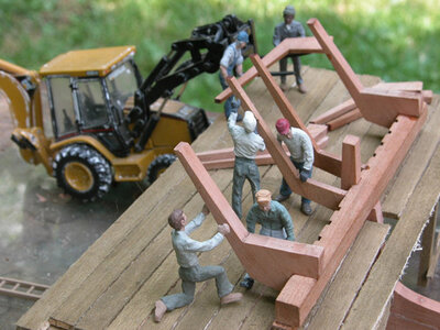
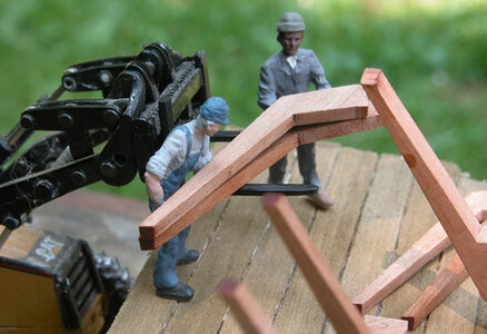
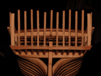
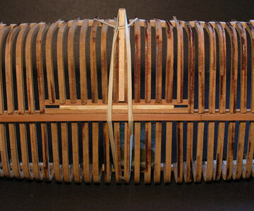
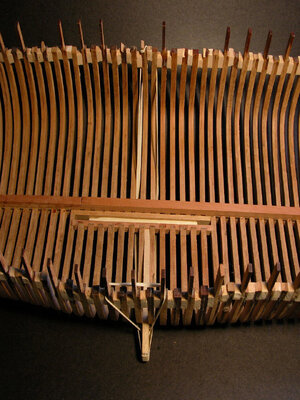
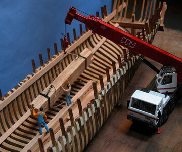
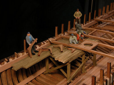
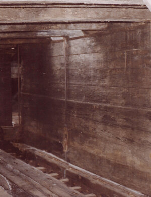
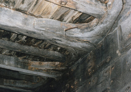
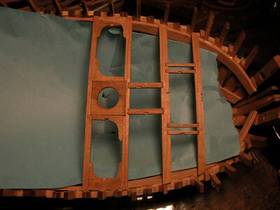
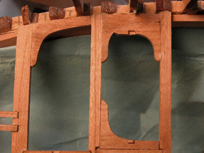
It’s the builders preference to build the stern on or off the model. Either way the key is being sure the timbers are set properly in their notches. You don’t want them to lean forward or backward and make sure they are square to the transom. A diorama scene shows how a stern would have been built. Scaffolding was erected to the height of the transom. Once the transom and stern timbers are secured in place the scaffolding is removed and the fashion timbers are set under the transom to help support it.

Sc1a.jpgSc2a.jpg
 
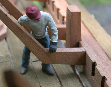
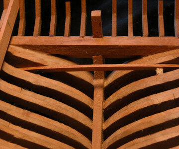
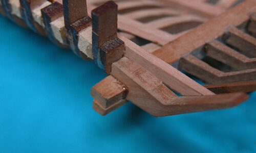
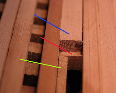
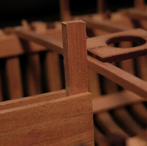
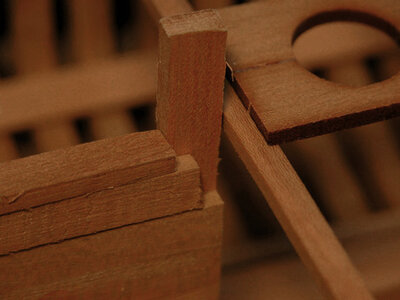
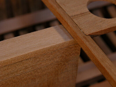
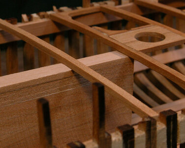
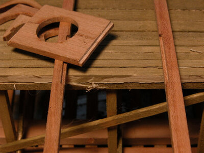
The transom has notches cut into the side. A lower timber on the bottom of the transom acts as a ledge for the stern timber to sit on. These stern timber have to be set at the correct angle so be sure they fit into the notch by checking the top and bottom for a tight fit in the notch.

Sc3a.jpg

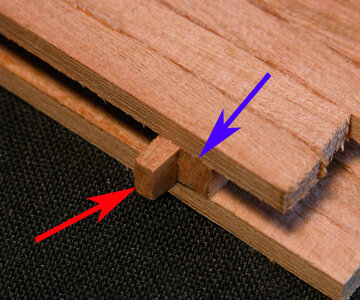
On the ends, the stern timbers are much thicker than the rest. These are made this way because they will need to be cut and shaped to make the rounded corner of the stern. The two end pieces are notched over the transom.

Sc4a.jpg
 
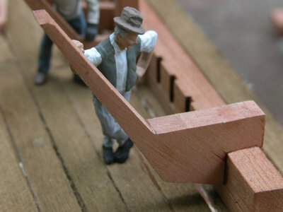
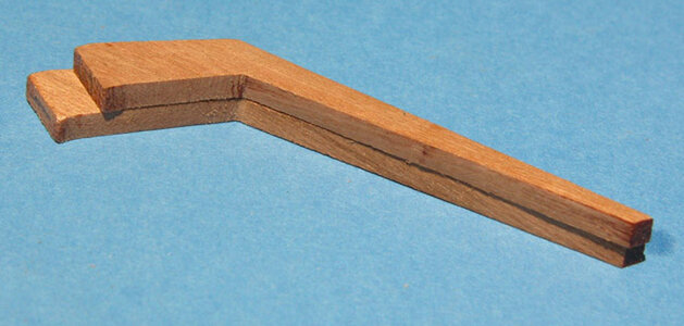
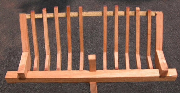
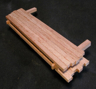
There are five stern timbers per side and each one is specifically cut for its location. In the photo the bottom timber is timber number one, which fits at the center of the transom, the one on top, is timber number five. Notice the difference in the length of the bottom section. As the timbers approach the ends of the stern the top sections progressively become shorter.

Sb3a.jpg

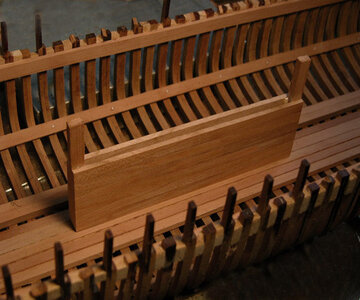
Starting with the number one timbers, they are set into the notch with a block being used to square the timber with the transom.

Sb4a.jpg

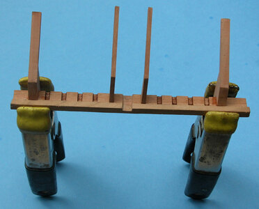
Number one timbers are set into place on either side of the center of the transom. The two heavy end timbers are also set into place

Sb5a.jpg

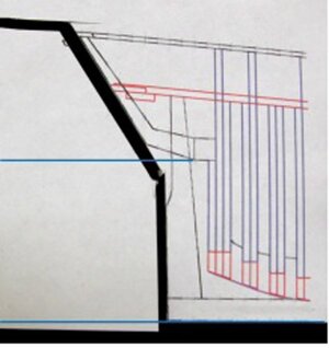
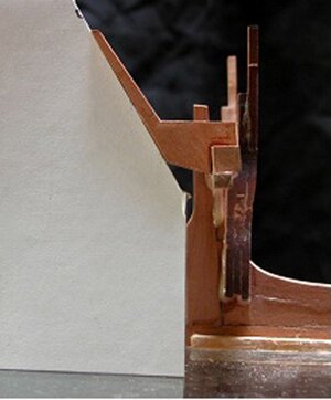
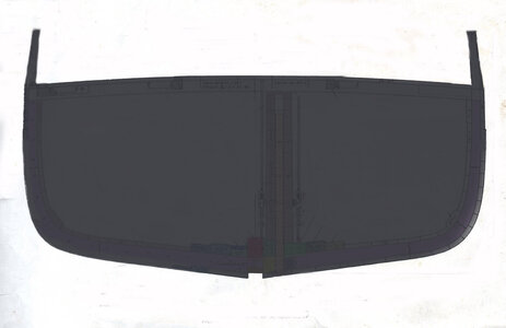
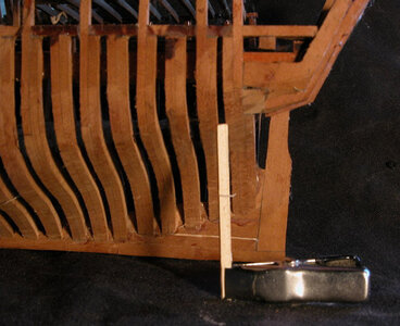
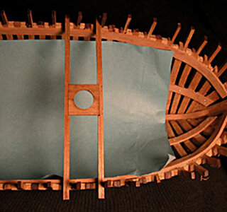
To insure the stern timbers do not lean to far back or forward a copy was made of the stern from the drawings. The drawing was glued to a piece of cardboard and used as a template. If your building the stern off the model cut the template at the bottom of the transom shown by the top blue line. If your building the stern on the model the template is cut at the bottom of the keel.

stern15.jpgstern16.jpg
 
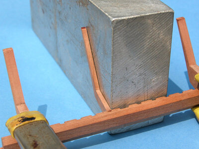
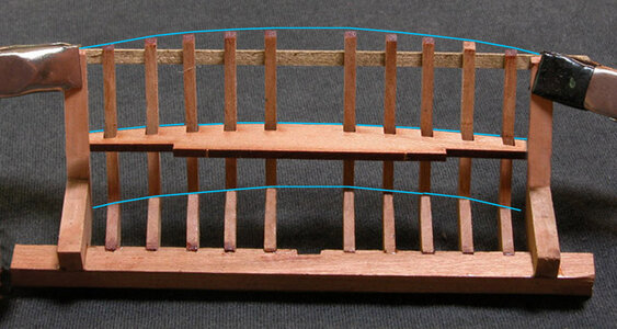
The reason for setting the center and end timbers in place is to create a cradle for setting the rest of the stern timbers. There is an arc to the stern so you want to bend a strip of wood as shown in the photos. Using both the strip and the template you can be assured the stern timbers will be set in the right place and at the correct angle. In the photo below the waterway is used as a guild to make sure the stern timbers have the proper spacing and fit into their notches.

Sb6a.jpg

the waterway is used as a guild to make sure the stern timbers have the proper spacing and fit into their notches.

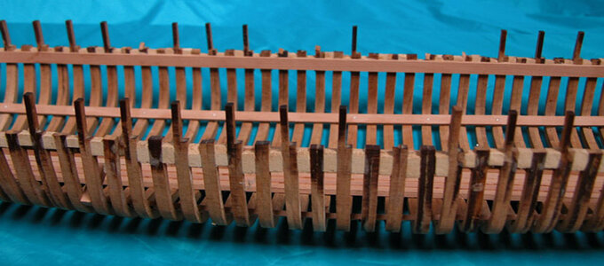
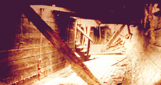
Looking at the final assembly of the stern timbers from the inside. Here you can see the arc at the top of the stern formed by the different lengths of the timbers, as well as the same arc at the bottom of the stern. These arcs can be seen clearly in photos of the wreck. The stern has three distinct arcs, one at the top and one at the bottom of the stern as well as a third arc from the center out to the ends, which can be seen on the waterway.

Sb7a.jpg

sc7aa.jpg
 
The final step in the construction of the stern section of the hull is placing the last frames. In larger hulls these frames are canted towards the stern, in the Alvin Clark’s hull these frames were set square to the keel. Like the half frames in the mid section of the hull, the stern frames are also made in pairs just like the forward cant frames. The last four sets of frames are cut larger than the actual size of the frame to allow for beveling the inside and outside edges.
Some builders would rather pre shape the inside bevels before installing the frames into the hull. This is a matter of builder’s choice. Personally I like to install the full frame blank and shape the frames once they are set in the hull by using various types of sanding disks.

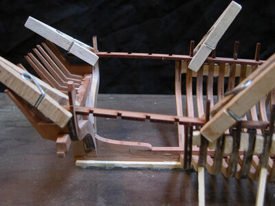
Setting up to install the stern frames is the same as we did for the rest of the hull. First temporally clamp the waterway in place,
sF1a.jpg

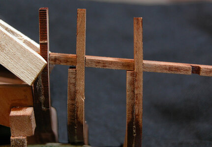
With the waterways in place it’s just a matter of hanging the frames in their notches. Notice the frames rise at the foot as they approach the last fashion timber.
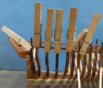
sF4a.jpg

Be sure the frame is high enough in the waterway notch so the frame fits tight to the bottom of the waterway like the frame on the right the frame on the left side needs to be pushed up .
sF2a.jpg

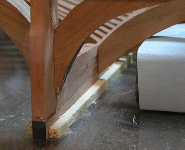
Clamping the foot of the frames to the deadwood can be a problem. One way I solved this is to use a square steel block I have. This block is 1 x 2 x 3 and comes in handy for many little tasks. In the photo I wrapped a piece of white paper around the block to clearly show the contact point at the frame. In different areas of the model I will use different glues, in this case I used a 5 minute epoxy. You just apply a little epoxy and push the frame until it makes contact with the deadwood. It takes 2 minutes for the epoxy to grab and 5 minutes for it to set. You can move to each frame one right after the other rather than having to wait for a slow setting glue. At this point the hull is still sitting on the glass building plate and the keel is set between the between the wood strips. By applying pressure against the frame with the block the hull stays put.
sF3a.jpg

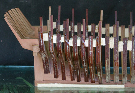
Once all the frames that fit into the waterway are in place the short frames are set between the frames using filler blocks. The frames that are in the waterway set the shape of the hull, so adding the short frames between these set frames is just a matter of lining up the face of the frames by feel. The entire framing of the hull is now tied together from the last fashion timber all the way to the bow.
sF5a.jpg

symmetry is the key in framing a hull, to a point you can sand the hull to even out high and low spots and shaping up both sides, but you still need a symmetrical structure to start with.
Looking at the hull from the bottom through the glass building plate you can see the stepping of the half frames. The stepping is a great visual guild for setting the frames. You can see that both sides of the hull are equal and the stepping is about the same distance from frame to frame. When the hull is sanded and the bevels are created the frames will flow one to the other.

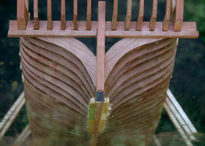
The hull of any ship is an art form embracing symmetry and the flow of curves one into another and graceful lines of the sheer profie. The planking flows from the stern to the bow in tapering curves. Even a Great lakes working cargo ship has it's beauty.
sF6a.jpg
 
Last edited:
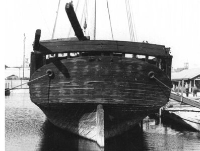
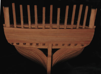
A clear photo of the stern not only gives use the shape but also the number of planks.

B&W sterna.jpg

before going on with the build i planked the stern because all yhose stern timbers are easly broken off, the planking will stiffen up the stern structure


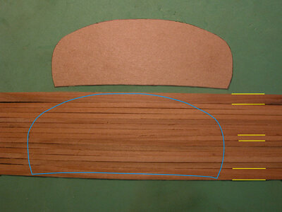
To begin a template is made for the shape of the stern then planking is laid out. Note the top and bottom planks are wider than the middle planks. If the top and bottom were the same width you would end up with a sliver of a plank on the top and bottom.

stern templatea.jpg

Once the planking is laid out masking tape is used to hold them together while the shape is cut out.

stern tapea.jpg


Begin the stern planking with the first lower plank making sure it is level with the stern frames. If you have a stern frame sitting to low just sand the frame to match the bottom of the plank.

stern one planka.jpg

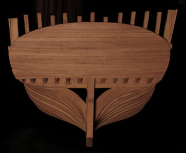
Continue to plank the stern making sure you end up at the molding on both sides. This will insure once you finish the top half of the stern planking it will be level and you will have an even space between the top of the planking and the cap rail.

stern bottom planksa.jpg

and the finish

full plankinga.jpg
 
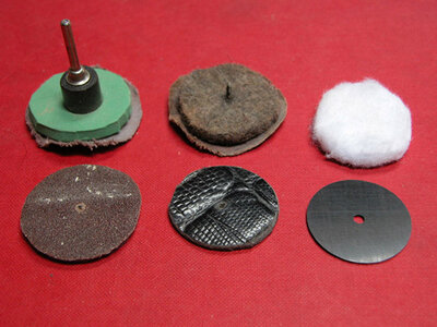
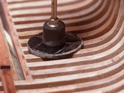
with the bow and stern framing complete the next step will be to sand the inside of the hull so the keelson will sit on the floor timbers. Below in the photograph are home made sanding disks. The green one is made of a foam rubber found in the garden center of any home improvement store. They are sold as kneeling pads. The next two are different thickness and firmness of felt, the middle one at the bottom is a piece of leather cut from an old belt and the last is a stiff plastic. These disks can be made of anything you salvage from around the house. The sand paper is just cut from sheets and don’t have to be perfectly round.

J1a.jpg

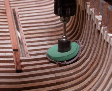
The disks are mounted on the rubber part of the Dremel drum sander. The reason for using soft and flexible disks is so they conform to the shape of the hull. The sandpaper is cut larger than the disk so it curls up the side of the disk.

J2a.jpg

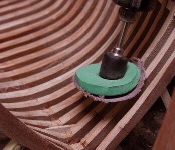
The three photos show how the disks are used to sand the inside of the hull. The first photo the rubber disk is bent and the sand paper is wrapped up on to the side of the disk to sand in things like the bevels on the forward frames.

J3a.jpg

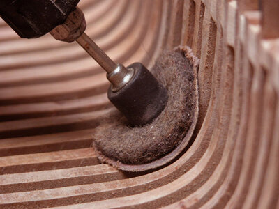
The felt disk is flexible enough to be cupped to form into the turn of the bilge. One note is the sand paper will catch on the edges of the frames and rip. You can apply rubber cement to the paper and the disks to keep the sand paper from ripping. Or have a supply handy and keep replacing the paper if it crinkles.

J4a.jpg

The stiffer disks are used at the floors and any areas that are flat or sort of flat. The stiffer the disk the faster it will cut. When pressure is applied to soft disks they tend to bend away from the surface and the sanding action is light. When you want to cut something fast use harder disks.

J5a.jpg

I am not using the thin sandpaper sheets i use sanding belts which are much thicker and have a cloth backing making the home made disks less likley to rip. There are also two types of sandpaper belts Aluminum Oxide which is red in color and used for wood working, you can get a variety pack from 36 to 600 grit then there is the silicon carbide belts which are use to grind glass, metal and used in lapidary (stone cutting) work. Silicon carbide belts are sharp and aggressive cutting and hold up much better than the Aluminum Oxide. You can get silicon carbide from 36 to 10,000 grit.
A trick to cutting out the circles is to score the back side with a knife and crack the circle out. It is difficult to cut the circles with a pair of scissors.

I also cut strips and glue them to a stick and make home made files.
 
Building plank on bulkhead model is building a model showing what a ship looked like, building a plank on frame model not only shows what the ship looked like but also how it was built. There is no detail in a bulkhead hull it just gives the shape of the hull to be planked over

bulkhead.jpg


Getting into scale ship building there is a lot going on outside the hull as well as inside the hull

img316 no text.jpg

i started the inside before i realized how easy it was to damage the stern structure. Planning the sequence of the build is important because you can create problems down the line.

hold1a.jpg
 
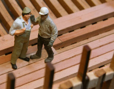
oh my! we seem to have a problem, looks like the yard forman and the boss are having a confab down in the hull.

cb2a.jpg

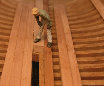
What i do is work the model then set up a scene with the little people. I like taking the pictures in a dim lit room so i can control the lighting. so i will set up the shot and go about other business. Coming back to the build sight i find there are missing little people, Without disturbing anything else a little person is plucked from the scene and is gone. Now that is odd.
According to the yard forman the crew is on strike and will not return due to rumors of alien abductions, witness say they saw big glowing eyes and in an instant someone is gone.

141a.jpg

This went on for days until i caught the alien in the act of abducting a worker. They were right about the big eyes. The "alien" is Mu not moo like a cow Mu like the ancient civilization. Some workers were recovered some lost and gone forever.

1417a.jpg
 
OK lets get back to work here

hold1a.jpg

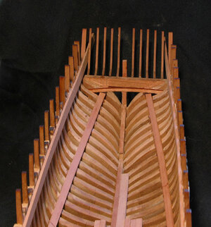
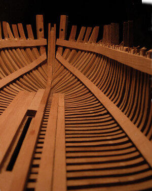
Taking a look inside the hull we can see some timbers installed. The one timber stretching from bow to the stern is the bilge stringer, The ones in the center of the hull are sister keelsons. The sister keelsons diminish in thickness as they get farther from the center of the hull. In the real Alvin Clark these keelsons were cut down to produce a smooth floor in the hold. These timbers were quite thick so they didn’t run the full length of the hull, they lay flat on the frame floors so there was no bending involved. One the centerboard side of the main keelson the sister keelsons fit tight to the side of the main keelson. On the other side the sister keelson starts farther away from the main keelson leaving a space. This space was covered by an inspection board and used to clean out the bilge.

hold4a.jpg

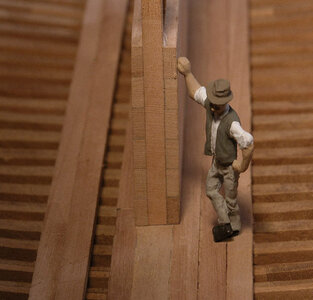
A final inspection of where the centerboard trunk will sit is given the ok to begin building the trunk. To the right is the first timber which is setting against the keel, a second trunk timber will bring it up level with the top of the keelson. The first sister keelson running along side the keelson stops at the center of the frame leaving a ledge for the end timber of the centerboard trunk to sit on. You can see this ledge at the foot of the figure Again to the right of the keelson the inspection space can be clearly seen. Blocks are set on the floors and spaces about every 5th frame. Then an inspection plank is set on the blocks, which can be removed to clean out between the frames.

hold2a.jpghold3a.jpg

Before any timbers are set in place in the hull it is necessary to insure the hull is straight and even. The slot for the centerboard may bow inward or outward. To make sure the hull remains straight a spacer is placed in the centerboard slot and held in place with rubber bands. At this stage the hull is still flexable. When the hull is aligned the keelsons are glued and pegged into place. Once the keelsons are placed in the hull, the hull becomes much stiffer.
 
After the hull is secured and the keelsons are in place the next item is the bilge stringers. At mid ship the stringers are placed at the turn of the bilge. In the stern the stringers are set so the beams of the cabin floor will sit on them. A measuring stick cut to the height of the cabin floor, this measurement is taken from the plans. Set the last floor joist to the correct height and clamp it to the frames. Run the stringer under the beam and allow it to curve down to the turn of the bilge. At the bow allow the stringer to take a natural sweep and end it on the hawse timbers. Any timber under stress due to bending it is a good idea to pin it in place rather than to rely on glue alone.
hold6a.jpghold7a.jpghold8a.jpghold9a.jpg


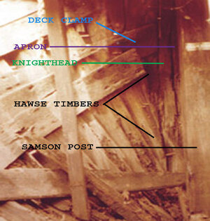
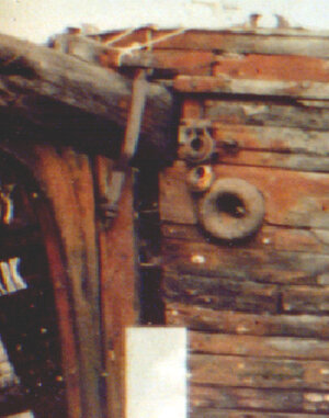
In the photo below is the actual bow of the Alvin Clark, with each piece identified. Notice the bilge stringer stops on the hawse timber. The deck clamps also stopped at the hawse timbers which created a weak connection between the hull sides and the stem. In the second photo you can see how the sides of the hull pulled away from the stem leaving a gap. The light area below the gap is sheet metal nailed to the hull and stem.

bow timbersa.jpg
hold10.jpg
 
clamp1a.jpg

One very useful item is spring clamps they come in all sizes and straights. Notice the notched waterway i was using when building the hull is no longer there. That worked out perfectly when setting the frames up but when it can time to build the deck i saw the problem. The ends of the deck beams sit on the deck clamp and under the waterway. The beam length goes to the inside of the frames so they are longer than the space from the inside edges of the waterways. I could take the shorted beck beams and place them in the hull at the mis section and slide the forward and back. But the medsection of the hull is straight for 3/4 of the hull so only a few deck beams could be set in place. I had no choice but to rip out the waterways.
clamp2a.jpg
. The deck clamps are positioned on the hull by using a spacer. This spacer is the piece of wood running along the top of the clamp and held in place by the smaller spring clamps. This spacer is the same size as the thickness of the deck beams. Starting at the top of the frame timbers as a guide run the spacer from the bow to the stern giving it a nice smooth curve. The curve at which your running the spacer is setting the sheer line of the hull. The spacer also represents the space between the deck clamp and the waterway.

clamp3a.jpg

I let the space run in a natural smooth curve rather than follow the tops of the frames.


clamp4aa.jpg

As the spacer is clamped to the hull each clamp is spaced apart and the spacer piece is bent to a smooth curve along the hull. Once your satisfied with the sheer more clamps are added to hold the spacer in place. This one spacer piece will set the sheer of the deck as well as the sheer line of the hull so it is important it is set right. The curve is more inportant than trying to hit the tops of the frames.

clamp5a.jpg

The deck clamp is a heavy timber and difficult to bend dry. Before installing the deck clamp soak the end in hot water for 10 to 15 minutes. Clamp the deck clamp to the hull and allow it to dry. This timber takes a compound bend. It first bends to the curve of the hull, then sweeps up and finally has a little twist as it sits against the inside of the frames. Bending is much easier if the wood is wet .

clamp6a.jpg

The deck clamp ends on the hawse timbers at the bow and runs to the stern timber at the stern.

clamp7a.jpg
The final deck clamp in place. Note the missing top timbers, these broke off when i removed the original waterways. I will deal with this issure later in the build.
 
The centerboard trunk would have been built in the hull on the actual ship. Starting with the end posts set in place the side timbers would be stacked and drift bolted together, a crane unloads the timbering i

centerboard1a.jpg


On the model the trunk is a simple build. Six timbers were edge glued laying flat on a table using a weight to insure it remains flat. Next the end posts were glued in place and the second side glued to the posts. The distance between the posts is critical because the ends have to sit on the ledge in the hull. I left the sides longer as I was building the trunk, once the sides were in place I sanded the trunk on a disk sander. The trunk is not glued in place until it is fitted under the deck beams.

centerboard2.jpg

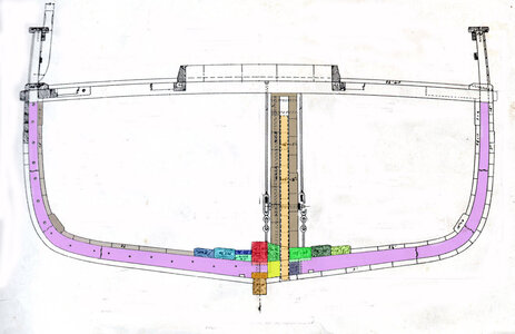
The next two photos show how the trunk fits to the hull. The area directly next to the center keelson is filled with a timber to bring it up level with the top of the keelson shown by the green line. The bottom of the end post shown by the blue arrow sits on top of the sister keelson shown by the blue line. The bottom of the end post shown by the red arrow will sit on the ledge shown by the red line.

centerboard3a.jpgcenterboard6a.jpg

The trunk was not built to the final height, this was done because the trunk has a cap and the deck beams sit on the cap. Once the deck beams are in place the top trunk timber is adjusted then a cap is set on the last timbers.

centerboard4a.jpg

the actual trunk on the Alvin Clark

A20a.jpg

ok that was an easy build.
 
Building the deck
deck1a.jpg


If you were to start framing the deck at the edge of the cabin or at the bow and worked in one direction you might end up out of room because the slightest errors add up over the length of the deck.. To avoid this the deck is built in sections so the masts, hatches and the windlass will fall in the correct location. Once these sections are built the deck is filled in the open areas.

deck layout 1Aa.jpg


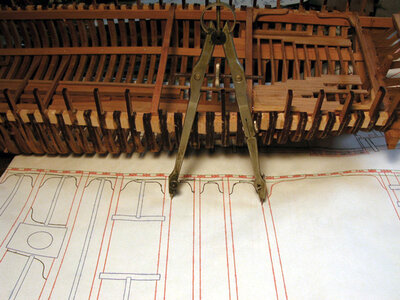
Starting the deck at the location of the cabin use a set of dividers and measure from the edge of the cabin beam to the edge of the hatch beam. As you can see we are skipping the two beams between the hatch and the cabin. These will be fitted later.

deck3a.jpg


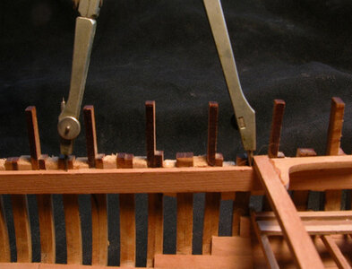
Take the measurement from the plans and transfer it to the model. With the dividers make a pinhole mark on the top of the deck clamp on both sides of the hull to insure your beam is parallel to the cabin beam.

deck4a.jpg

i laser cut the beams longer than the width of the hull, so they can be adjusted from side to side if needed.. Before i install the first beams into the hull i cut the notches for the carlings to sit in, the location of the notch is taken off the drawing.

deck5a.jpg


A little card trick is to use a square piece of cardboard and set it on the beams even with the edge of a beam. You can see if your carlings are square to the beams. Adjustments are made by cutting the ends of the beams, so you can slide them back and forth until the carlings are square

deck6a.jpg

With the first beam in place notch the ends of the carlings that in the beam notches and cut the notch for the ledges


.
 
The next sets of deck beams to place in the hull are the beams that hold the mast partners. Glue the two halves of the partners together then cut the grove so the partners set flush in the beam notch. Cutting the grove is not difficult, use a new sharp single edge razor blade and make a cut back from the edge. It will take a few passes to get the cut deep enough. Once the cut is made its a simple process of chipping out the material.

deck7a.jpg

Once the partners are glued in place set the beams in the hull. The beams will be to long so center the mast partners in the hull then mark the ends of the beams and cut the beams to fit.

deck8a.jpg

What i did was cut all the deck knees as larger blanks that have to be cut and fit to the deck. Once the two beams are fit to the hull go back and fit the knees. If the knees are to large to fit between the beams cut the “arm” of the knee shown by the white arrow.

deck9Aa.jpg
 
Last edited:
We have now reached the section of the deck which goes over the center board trunk, the green beams. The method used to construct this section of the deck is to place and glue in the knees but leave the beams removable. The reason for not gluing down the beams is so the centerboard trunk can be set in finished and capped. To do this the beams would be in the way so they have to be removable. To just finish the trunk you need to know the exac theight of the beams. Finishing the trunk and setting the beams have to be done as one operation.

Sometimes you need a plan way ahead of the build or you may end up ripping stuff out.

deck drawing1.jpg
 
Last edited:
Construction of this section of the deck begins with the measuring and placing of the two deck beams shown by the white arrows, Measure off the plans from the last mast beam to each deck beam as shown by the green arrows. With these two beams set in place fit the knees between the mast beam and the first beam shown by the white arrow.

deck15Aa.jpg

The four deck beams which go over the center board weret not be glued in place. Only the knees are glued in to locate the deck beams. The photo shows one of the deck beams removed after the knees are placed.

deck15A.jpgdeck16a.jpg
 
When the trunk was built the end posts were left oversize and the last side board and cover plank were left off. This was done to allow for a perfect fit under the deck beams. When the center board trunk was built it was not glued into the hull so it could be removed later and fit under the beams.

deck11a.jpg

What i did here is to set the last side plank and cover board on top of the trunk. IThen i sanded down the cover board until the trunk fits snug under the deck beam. to much height has to be taken off the cover board i sanded down the last side board. You don’t want the cover board to be to thin. Each end post is cut down to the top side board and the cover board fits over the end post. Then the end post and cover board fit under the deck beam.

deck12a.jpg
deck13a.jpg

i checked along the top of the center board and make sure the deck beams from front to back will sit on the top of the center board.

deck14a.jpg

The photograph shows the actual center board trunk with the deck beams sitting on top of the cover board.

alvin 41.jpg

A picture od the knees along the deck clamp. Ships of war will have hanging knees but the Alvin Clark only had lodging knees.

kneesa.jpg
 
Last edited:
The last section of the deck to build is the area of the forward mast and windlass and the forward hatch just like the last mast partners i glued the two halves of the mast partners together, then notch the edges and set the piece into the beams.

deck7a.jpg

With the mast partners and beams glued up as a unit center it in the hull and trim the ends of the beams.

deck21a.jpg

Working forward from the 2 beams holding the mast partners the two carlings were fit forward and into the next beam, The beans for the windlass are bigger than the rest of the deck beams. Two sets of windlass braces and set into the beams that will hold the windlass braces in place. Once the mast beams were set the rest will fall into place the only concern here is to keep the structure square.

deck23a.jpg

Starting with the mast beams i installed the knees at the partners and at the sides of the hull Finally fit all the deck knees.

deck22a.jpg
 
Back
Top