-

Win a Free Custom Engraved Brass Coin!!!
As a way to introduce our brass coins to the community, we will raffle off a free coin during the month of August. Follow link ABOVE for instructions for entering.
-

PRE-ORDER SHIPS IN SCALE TODAY!
The beloved Ships in Scale Magazine is back and charting a new course for 2026!
Discover new skills, new techniques, and new inspirations in every issue.
NOTE THAT OUR FIRST ISSUE WILL BE JAN/FEB 2026
You are using an out of date browser. It may not display this or other websites correctly.
You should upgrade or use an alternative browser.
You should upgrade or use an alternative browser.
usually you would need also the longitudinal lines
usually... but not in this caseusually you would need also the longitudinal lines
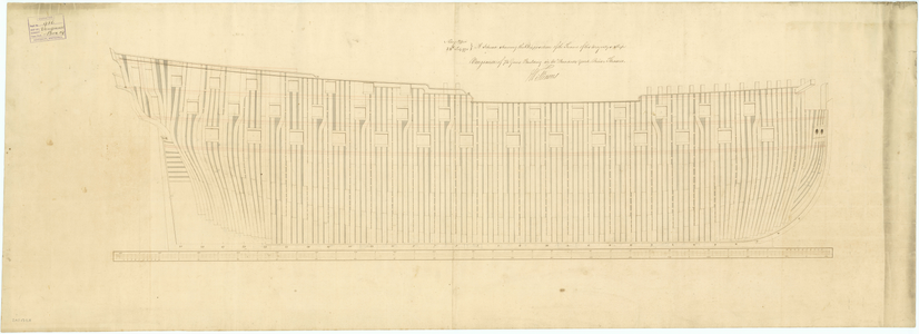
If you are going to fully frame the model you need a number of things such as the station lines and room and space. Once in a while there are framing disposition drawings that show exactly where the frames go. This probably does not apply very well to the Charles Morgan, but for what it's worth the R&S can be found for English ships in contracts and in the Establishments as well as in Steel's The Elements and Practice of Naval Architecture and The Shipbuilder's Repository 1788 for various eras. The futtocks vary in breadth as well, but the floors and first futtocks are the key pieces to be located on the keel. I doubt you will find many, if any, drawings of the framing dispositions before the second half of the 18th century so will need the scantlings from the sources mentioned above and a profile drawing with the station lines. If you do find some, PLEASE post them.
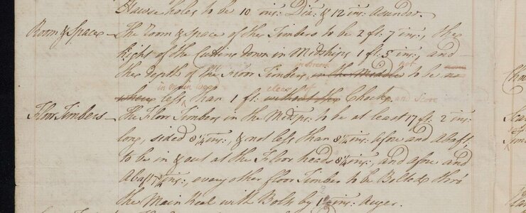
The R&S for a sloop of war, if based on the 1719 Establishment, was about 24" This was increased to 28" in the 1745 Establishment. The floors were probably sided about 11" This MIGHT not apply to a bomb vessel such as Granado although she was originally built as a sloop of war at Harwich in which case these scantlings could very well apply. If there is a contract in existence it would probably be at the National Archives in Kew. Even with the Establishments, based on contracts, these dimensions seemed to vary a lot. A part of a contract for a 20 gun of 1755 with a gun deck of 107 feet 8 inches can be seen below showing the room and space and siding of the floors.
Allan


Last edited:
You have a regular distance of the frames on the keel shown by the lines in the cross section
BTW: also the logintudinal lines are existing of the Charles W Morgan
 store.mysticseaport.org
BTW: also the logintudinal lines are existing of the Charles W Morgan
CHARLES W. MORGAN, Whaleship | Mystic Seaport Ships Plans
<p><a title="CHARLES W. MORGAN" href="http://library.mysticseaport.org/exhibits/morgan.cfm">CHARLES W. MORGAN</a>, a 113' 11" whaling bark, was built in 1841 by Jethro & Zachariah Hillman of Fairhaven, Massachusetts and named for one of the major shar
- Joined
- Dec 1, 2016
- Messages
- 6,349
- Points
- 728

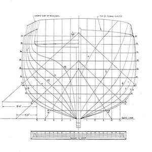
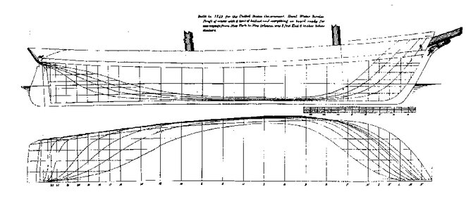
starting from this drawing... is it possible to trace the geometric position frames along the keel?
View attachment 456775
if your asking if you can draw all the frames between the station lines using just the bodyplan the answer is yes
- Joined
- Dec 1, 2016
- Messages
- 6,349
- Points
- 728

- Joined
- Dec 1, 2016
- Messages
- 6,349
- Points
- 728

another way to get all the frame shapes is to build a half model
starting with the bodyplan
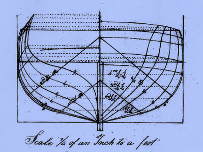
use the body lines and cut out blocks to the lines. Use a soft wood or high density foam board and pin them together. Don't glue them because you will have to take the hull apart.
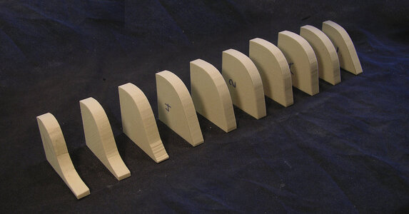
depending on how far apart the bodylines are placed along the hull and how many frames between them you add blocks for each frame.

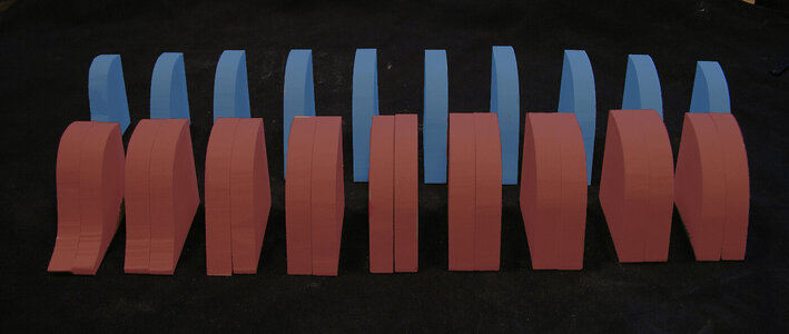
the rough hull before sanding

now sand the hull to its shape by using the original bodylines as a guide


you will have all your bevels done
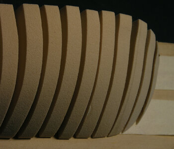
take the hull apart and either scan the pieces or use them as a template and trace around them
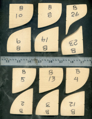
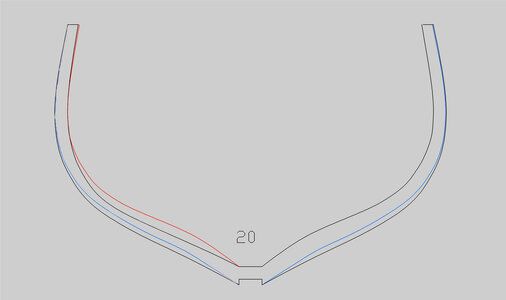
starting with the bodyplan

use the body lines and cut out blocks to the lines. Use a soft wood or high density foam board and pin them together. Don't glue them because you will have to take the hull apart.

depending on how far apart the bodylines are placed along the hull and how many frames between them you add blocks for each frame.


the rough hull before sanding

now sand the hull to its shape by using the original bodylines as a guide


you will have all your bevels done

take the hull apart and either scan the pieces or use them as a template and trace around them


- Joined
- Dec 1, 2016
- Messages
- 6,349
- Points
- 728

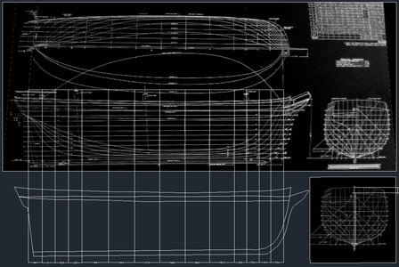
This is the drawing I'm working on.. The CAD gives me these distances between the frames:
36.4 34.4 35.9 35.9 70.3 69.3 67.3 66.8 65.3 66.3 31.9 33.4 31.4 33.4
At this point I can correct the values and make them consistent with each other.
they should not be the same distance apart. as the curves of the hull change the closer together the station lines become. Midship where there is little change in the shape of the hull so the station lines will be farther apart.
Hi Davethey should not be the same distance apart. as the curves of the hull change the closer together the station lines become. Midship where there is little change in the shape of the hull so the station lines will be farther apart.
Is this particular to the Charles Morgan or merchant ships or whalers in general? I had never seen the station lines being different distances on British navy vessels so this practice is new for me. I have seen where the distance from midships (0) to stations (1) and (A) are smaller than the others otherwise the distance never varied. I realize it is common that every other station is marked for most of the length as seen below, but there is no variation from station to station. What am I missing?
Thank you very much.
Allan
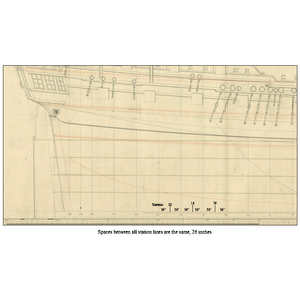
Last edited:
- Joined
- Dec 1, 2016
- Messages
- 6,349
- Points
- 728

- Joined
- Dec 1, 2016
- Messages
- 6,349
- Points
- 728

- Joined
- Jun 29, 2024
- Messages
- 1,454
- Points
- 393

What appears on lines drawings (aka draughts) are “stations.” Stations do not always represent actual frame locations. They exist primarily to define the shape of the hull. Original drawings for warships built in well organized admiralty dockyards (British) often locate stations at anticipated frame locations. In other cases this might not be true. In American yards building merchant ships, the lines drawing might have been skipped entirely in favor of a half model from which dimensional information (offsets) was generated. In all cases, the final determination of hull shape and exact frame location was subject to location on the mound loft floor.
A special problem exists with models of American vessels built from non original drawings; Chapelle’s being a prime example. Many of these come from two sources, Dimensions lifted by the British from drydocked captured vessels, or hull shapes developed from half models in museum collections. In these cases information to locate frame locations would often be unavailable. The drawings are still accurate but station locations are independent from frames.
Roger
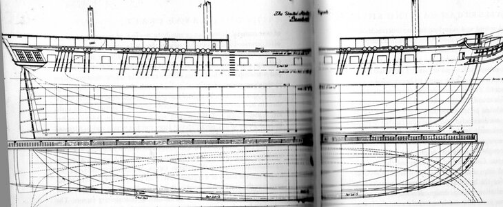
Dave, I agree with you that if the model builder is only making frames based on the stations shown on the plan rather than fully framed, they need to be attentive to their location on the keel. but I do not think the station lines are closer together, it is just that only every other station line is shown in the center area of the profile drawing. Same thing happens on the body plan. In the plan below on the left I sketched in stations 24 and 26 and marked 22, 24, and 26 on the profile view on the right in magenta. I can't tell from the pictures you posted but I venture to guess it is the same thing, they merely show every other station for most of the hull length. In the below the distance from station to station is always the same, 26 inches. but when the plan only shows every other station the distance is 52 inches. I think you can see in the drawing the original station numbers and not all of them are drawn in by the draftsman.here is an admiralty drawing that shows the station lines are closer together at the bow and stern
Allan
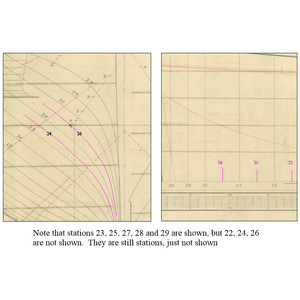
Last edited:
- Joined
- Dec 1, 2016
- Messages
- 6,349
- Points
- 728

I do not think the station lines are closer together, it is just that only every other station line is shown in the center area of the profile drawing.
i did measure the drawing in post #14 and your right the station lines at the bow and stern are the same distance apart as the midship ones the difference is a station line is added between the originals.
i did measure the drawing in post #14 and your right the station lines at the bow and stern are the same distance apart as the midship ones the difference is a station line is added between the originals.
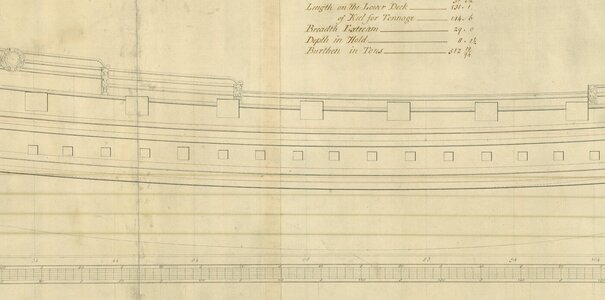
Thanks Dave, Yes the originals only include alternate stations and this seems to be common place on contemporary drawings. It gets even stranger at times. Examples from the 17th century are often different. The plan below does not follow the convention of numbers aft of midships and letters forward as seen in the 18th century and beyond. The stations are numbered from 1 aft to 124 forward and to add to this it only shows every tenth station line on the profile and body plan. It seems nothing is ever 100% in our hobby.
Allan
Allan

All very interesting, but no one has answered the initial question that gave rise to this thread
The answer is included in the posts by the others (I guess)All very interesting, but no one has answered the initial question that gave rise to this thread
This is the drawing I'm working on.. The CAD gives me these distances between the frames:
36.4 34.4 35.9 35.9 70.3 69.3 67.3 66.8 65.3 66.3 31.9 33.4 31.4 33.4
At this point I can correct the values and make them consistent with each other.
Looking at this post we can see , that you are already using the logintudinal drawing from the web-side
CHARLES W. MORGAN, Whaleship | Mystic Seaport Ships Plans
<p><a title="CHARLES W. MORGAN" href="http://library.mysticseaport.org/exhibits/morgan.cfm">CHARLES W. MORGAN</a>, a 113' 11" whaling bark, was built in 1841 by Jethro & Zachariah Hillman of Fairhaven, Massachusetts and named for one of the major shar
but off course in a the very bad quality - and caused by this you have the differences between the stations (which means not the frames like you wrote.
And by the way: You have also to differ netween the term
"frame" - which is the real frame of the real ship
and
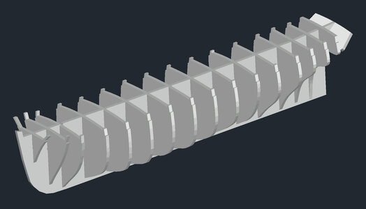
"bulkhead" - which means these false wooden boards we use for building a POB-model
I copied also the line drawing and resized it
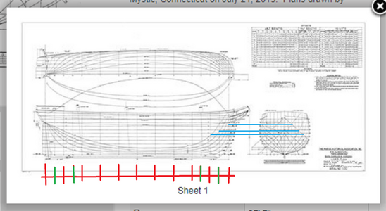
Like Allan mentioned the stations (red distances) on such a drawings have every time the same distance
and the stations in green are a half of the red distances
So you have to find out what is the correct distance (something between 67 or 68 ) - and afterwards you can adjust your CAD-drawing
Best would be off course to get the original drawing from the museum to get accurate measures
afterwards you can design your bulkheads or better define the location on your false keel - btw do not forget, that the lines are the outer ships lines, so you have to reduce the bulkheads by the hull planking thickness etc.


