• LUCZORAMA SHIPWRECK SCAVENGER HUNT GIVEAWAY. 4 Weeks of Fun • 1 Legendary Prize ((OcCre’s Fram Ship)) • Global Crew Welcome!
    **VIEW THREAD HERE**

Attempting 1st POF

  • Thread starter Thread starter 2G's
  • Start date Start date
  • Watchers Watchers 3
Joined
Mar 9, 2019
Messages
21
Points
58

1 (2).png
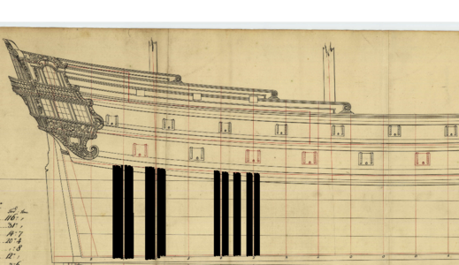
As the subject matters says, I have questions, (lots)! The drawings show 0-8 frames + the forward fashion frame aft and 0-7 frames fore, midships needing 3: 0 frames. All in all it doesn't seem like enough frames from station to station. (The frames depicted at station 3,4,6,7 I know are made double, I just left them separated at the station for clarity)!
So my first question: Is the hull framed only using the frame drawings given, and frame the hull as depicted at frame stations 6-7 making the frame thickness equal to the thickness between the two frames. Or does it need to be framed as depicted at frames 3-4 and figure out the shape of the of the frame or frames between the station frames with equal distance?
Question 2: There are no drawings of the counter timbers of the stern, how do I get an accurate drawing shape of those timbers?
Question 3: As with the counter timbers there are no drawings of the transoms from the stern post, how do I get an accurate drawing shape of those?
And lastly for now, the numbers showing at the bottom left, I am guessing the ship is 116' between perpendiculars, and 31' wide at midships, I think the language is Norwegian!
 
Which ship you are refering?
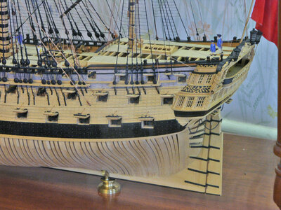
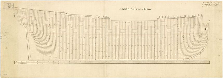
To assist Brians post please take a look at the existing contemporary drawing of the frame pattern of the shown Alfred

j2420.jpg
Scale: 1:48. Plan showing the framing profile (disposition) for Alfred (1778), a 74-gun Third Rate, two-decker.

 
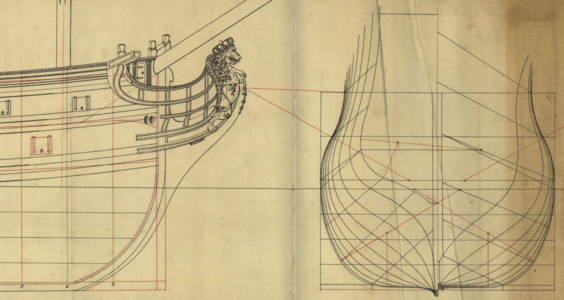
The ship is called the Afritz 44 cannons 1750. Scale will be 1:32! The reason I asked my questions is because I see all POF models framed like Brian's picture! The ship drawing represents the body plan existing of 10 frames aft, which include frames 0-8 and the fashion frame, and 0-7 frames fore. 0 of coarse being 0 for which 3 are represented on the sheer plan, what you see in the picture I originally posted representing placement of the frames, gun ports, and floors. The half breadth and the stern! Uwe looking at your sheer plan if I'm correct, shows a double plated station frame, I believe a space, a single frame, another space, maybe another single frame, a space, then another double station frame! So again the body plan doesn't show enough frame drawings to be placed between the frame stations, how do I get the correct shape of those frames? Also how wide are the frames and how deep(Thick)? I hope that I am explaining what I'm trying to figure out, correctly! I wish my sheer framing plan looked like that!
 
Last edited:
If you have a body plan the frames can be developed from it if not you could use the line drawing.

Can you post photos of your reference drawings?
 
Here is the body plancanvas.png
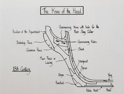
Since I have posted this picture as well I might as well ask this question concerning the keel the stem the gripe, and the knee. Other than how it looks in the drawing, am I to cut those parts as shown or somehow differently?
 
Of course, you can build the stem on your model however you like--even cutting it as a single piece if you want to keep it simple. However, If you would like to mimic construction of all the parts of the stem, Goodwin gives this image of the structure of the bow timbers for an English man of war from the 18th century (Construction and Fitting of an English Man of War, 1650-1850, p. 37).

20201117_111440.jpg
 
Last edited:
The questions you are asking show that you may want to achieve some sort of historical accuracy in your project.
The first step is to educate yourself as to the building practices adopted by the country of origin, once you actually know what ship you are working on.
From there, you would be able to determine many things: among them, the layout of the framing including whether the frames were sistered, the spacing between the frames, were the frames angled at the front (bow) and back (stern) of the ship or not, etc... etc There is a lot to learn ... and it makes no sense to build pof is you have no clue as to what was possibly done at the time and where the the ship was built.

And if you are not interested is achieving some sort of "historical accuracy" for that particular project, then the layout can be anything: as simple or as complicated as you would want it to be. Again, the secret is credible sources of information.

Just my 2 cents.
G.
 
As the subject matters says, I have questions, (lots)! The drawings show 0-8 frames + the forward fashion frame aft and 0-7 frames fore, midships needing 3: 0 frames. All in all it doesn't seem like enough frames from station to station. (The frames depicted at station 3,4,6,7 I know are made double, I just left them separated at the station for clarity)!
So my first question: Is the hull framed only using the frame drawings given, and frame the hull as depicted at frame stations 6-7 making the frame thickness equal to the thickness between the two frames. Or does it need to be framed as depicted at frames 3-4 and figure out the shape of the of the frame or frames between the station frames with equal distance?
Question 2: There are no drawings of the counter timbers of the stern, how do I get an accurate drawing shape of those timbers?
Question 3: As with the counter timbers there are no drawings of the transoms from the stern post, how do I get an accurate drawing shape of those?
And lastly for now, the numbers showing at the bottom left, I am guessing the ship is 116' between perpendiculars, and 31' wide at midships, I think the language is Norwegian!
Hallo @2G's
we wish you all the BEST and a HAPPY BIRTHDAY
Birthday-Cake
 
View attachment 193216
As the subject matters says, I have questions, (lots)! The drawings show 0-8 frames + the forward fashion frame aft and 0-7 frames fore, midships needing 3: 0 frames. All in all it doesn't seem like enough frames from station to station. (The frames depicted at station 3,4,6,7 I know are made double, I just left them separated at the station for clarity)!
So my first question: Is the hull framed only using the frame drawings given, and frame the hull as depicted at frame stations 6-7 making the frame thickness equal to the thickness between the two frames. Or does it need to be framed as depicted at frames 3-4 and figure out the shape of the of the frame or frames between the station frames with equal distance?
Question 2: There are no drawings of the counter timbers of the stern, how do I get an accurate drawing shape of those timbers?
Question 3: As with the counter timbers there are no drawings of the transoms from the stern post, how do I get an accurate drawing shape of those?
And lastly for now, the numbers showing at the bottom left, I am guessing the ship is 116' between perpendiculars, and 31' wide at midships, I think the language is Norwegian!
Hallo Greg alias @2G's
we wish you all the BEST and a HAPPY BIRTHDAY
Birthday-Cake
How is your POF project going?
 
Back
Top