Solid progress. The stain color looks nice!
-

Win a Free Custom Engraved Brass Coin!!!
As a way to introduce our brass coins to the community, we will raffle off a free coin during the month of August. Follow link ABOVE for instructions for entering.
-

PRE-ORDER SHIPS IN SCALE TODAY!
The beloved Ships in Scale Magazine is back and charting a new course for 2026!
Discover new skills, new techniques, and new inspirations in every issue.
NOTE THAT OUR FIRST ISSUE WILL BE JAN/FEB 2026
You are using an out of date browser. It may not display this or other websites correctly.
You should upgrade or use an alternative browser.
You should upgrade or use an alternative browser.
- Joined
- Mar 1, 2022
- Messages
- 684
- Points
- 308

You'd better buy the monograph from Ancre for good measure. If I was you, given the the relevant investment, I wouldn't trust blindly in kit plans.Does anyone know why Unicorn has samson posts in the cargo hold, pump well and shot locker? I had not heard of such a post, so Googled it. I could find no references for the post being in those locations.
Cheers!
Karl, from Nastätten - Rhein-Land-Pfalz - Germany, on the Nautical Research Guild forum has a superb scratch built BH cross section. He included two to access the main hatch (see photo below).
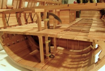
I suggest you review his log, It is incredible.
Also the Ancre monograph is another great reference. I'm on the road, so do not have it with me to look at. I did include them in my build. How else would one access the holds?

I suggest you review his log, It is incredible.
Also the Ancre monograph is another great reference. I'm on the road, so do not have it with me to look at. I did include them in my build. How else would one access the holds?
I have reached a good stopping point, so thought I would add to my build log and include some more photos. All the new wood since my last posting has one coat of Model Expo Pre-Stain Wood Conditioner, three coats of Occre Golden Oak Dye and two coats of Occre Satin Varnish. All faux nail heads are 1 mm drilled holes filled with Minwax Walnut wood fill.
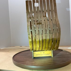
I built the display stand and glued the nameplate to it. This gave me a stable platform for working on the rest of the model.
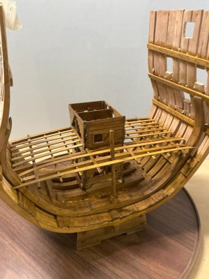
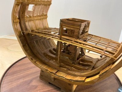
I glued three wood strips to both insides of the model, directly below the Deck 3 support beams as inside hull planking. I made two faux nail heads above each of the nine ribs on that planking. Also glued the support structure to these planks and the cargo hold planking and keelson. I made several faux nail heads in that support structure. This is the structure to which the cargo hold fence will be glued.
Not sure if I did something wrong or the notch in the samson post attached to this structure was in the wrong location, as the bottom of the samson post did not meet the support structure. So, I used some of the scrap wood from the kit to make a small pillar on which to glue the bottom of the samson post and then glue this pillar to the support structure.
I had a lot of issues with the pump well and shot locker on gluing them to the cargo hold planking and the mast support structure. The common wall and the front of the pump well hung in the air. I removed the lower three rows all around the pump well and shot locker, in order for the common wall and the front of the pump well to make contact with the mast support structure. I then removed one row from the pieces I had removed and glued the remaining two rows back in place. While not perfect, it’s a pretty good fit.
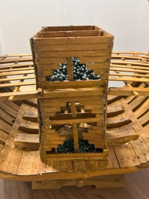
I decided on an hourglass shape for the openings I put in all four sides of the pump well and shot locker. I thought this pattern was more interesting than just a large rectangular hole. The bottom row of the opening is the entire length of that wall, other than 5 mm of wood strips at each end. Each subsequent row going upwards, decreases the opening by 5 mm on each end. I continued that until I had an opening less than 15 mm. I repeated that row and then expanded each subsequent row by 5 mm on each end.
I had to enlarge the notches in the support beams that went from side-to-side on which the support beams glued inside the sides of the pump well and shot locker go, in order for a good fit. Since I decided to add roundshot to the bottom and Deck 3 areas of the shot locker, I extended the 1 mm x 5 mm strips to go into the shot locker (there are two of them) to within 10 mm of the wall with the opening. Under that opening, I added a second ladder I made from 1 mm x 3 mm walnut strip I had left over from my Mamoli USS Constitution build, since I had no surplus cherry wood and the accessory kit only had enough cherry wood for a single ladder (the one in the pump well). I added a 2 mm x 2 mm wood strip to the front and back inside walls of the shot locker as additional support for the planking I put in the shot locker. Then I added roundshot to that placking and the cargo hold planking within the shot locker. There were approximately 250 cannonballs at the cargo hold level and 450 at the Deck 3 level as the Deck 3 level is bigger due to the mast support structure at the cargo hold level.
Even though I glued the roundshot to the cargo hold and Deck 3 planking, I added a small retaining wall to each area so that it would not appear that the cannonballs could roll right against the ladder in the shot locker.
Based on the dimensions of the shot locker and how many layers of roundshot I wanted to put in the shot locker, I purchased the above mentioned 700 3 mm black cannonballs made by a UK company called Caldercraft. Since they were a UK company, I was hoping my favorite overseas hobby shop would carry their products. That shop is Cornwall Model Boats in Cornwall, England. Luckily for me, they do carry Caldercraft products, including the 3 mm black cannonballs (roundshot). Caldercraft packages 50 cannonballs per packet. Thus 14 packets for the 700 cannonballs. I also ordered another 2 packets to replace the 80 3 mm steel balls that came in the basic kit. The cost of the roundshot (800 balls or 16 packets), including shipping from Cornwall to Massachusetts was almost $56. That might seem a bit expensive, but if you do the math, it comes out to 7 cents per cannonball. Not a bad price, considering I do not have to put two or three coats of black paint on 780 steel balls!
I could get one side of the 1 mm x 5 mm wood strips that form the Deck 3 planking support to stay right on top of the Deck 3 support beam; but not the other side. There is enough flexibility there so when I put the inside hull planking (bulwarks) against the Deck 3 support beam, it should hold those support planks in position, against the Deck 3 support beam.
Here are the photos of my work since my last posting:
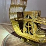
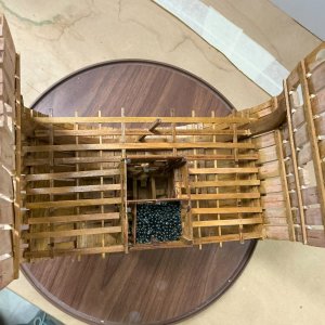


Hi Henry. My suspicion is you inserted them as thumbnails. Nice model!Not sure why three of my photos are so small.
- Joined
- Apr 12, 2025
- Messages
- 290
- Points
- 158

I second that! "Nice model, too!"Hi Henry. My suspicion is you inserted them as thumbnails. Nice model!
Coming along nicely! I like the storage full of your custom ordered cannonballs!
Thanks for sharing.
Thanks for sharing.
Hmm. Just be sure to Insert: Full image.Will try again to see if you are correct.
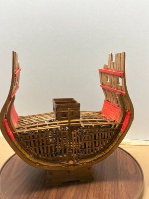
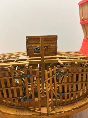
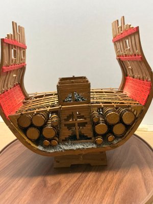
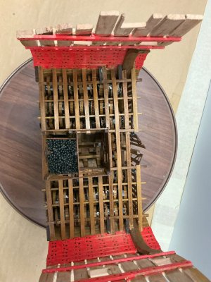
Since my last posting I have completed all the work below Deck 3, the orlop deck, except for the mast and bilge pumps.
As you can see, the fence and two gates from the accessory kit are in the cargo hold. The hinges were made from 0.5 mm thin brass sheets, cut 2 mm wide and 20 mm long. One end of the hinge I bent into a circle to go around the hidden hinge pin, which is a 2 mm diameter brass rod that is 4 mm long. The plans showed 14 mm of a hinge visible, but prior to cutting the hinge from the brass sheet, I wanted to know how much to add for the circle that goes around the hinge pin. So. being an ex-math major, I used my junior high, or middle school for my younger viewers, geometry class knowledge to calculate the circumference of the circle I needed to form; namely Circumference = 2*Pi*Radius or Pi*Diameter. I used 3 for Pi and the circle diameter is approximately the same as the diameter of the rod it will go around; therefore 2 mm. Hence the circle circumference is 6 mm of the 20 mm long brass strip. I glued the non-gate hinges around half of the 4 mm long brass rods (hinge pins). The gate hinges were placed with the circle of the hinge over the remaining portion of the pins but not glued to the pin, so that they easily swing open and close. I snipped a 1 mm diameter nail head of small brass nails from a previous project and glued 3 detached heads to the front of each hinge. These represent the end of bolts of a real hinge to secure it to a real fence and gate. Finally, I painted the nail heads, hinges and top/bottom of the hinge pins with Model Expo Iron/Cannon Black paint.
The ballast are small grey stones I got via Amazon from a model railroad supply company. If I was into trains, I would use the stones as bedrock on which I would place my railroad track ties; but for a ship modeler, it was the perfect material for ship ballast. I used a glue brush with Gorilla Clear Grip glue on it, to place glue on the cargo hold planking and then placed a layer of stones on top of the glue, using a plastic teaspoon. I attempted to repeat this process, by placing the glue via the glue brush on top of my layer of ballast. This is similar to how I glued the cannonballs in the shot locker. Unlike the cannonballs, which stayed attached to the planking, when I lifted my glue brush from them, lifting my glue brush from the small stones, caused most of them to remain adhered to brush. So, I switched to using Gorilla aerosol adhesive, instead of my glue brush with the Gorilla Clear Grip glue. I was hoping to place a plastic straw, like what comes with a can of WD-40, on the Gorilla nozzle, to be able to precisely direct the glue. Unfortunately, the plastic straws I ordered from Walmart did not fit the Gorilla nozzle. The nozzles that came with the straws did not have the hollow plunger to force the adhesive up the nozzle and through the straw. So, on to Plan B. I used masking tape on the model, to protect the areas where I did not want the glue to go. This worked. I built the stones on top of each other until they were level with the mast support beams.
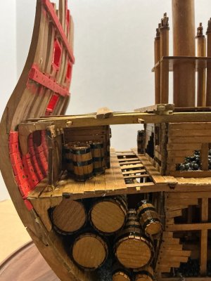
On top of the ballast, those beams and then each other I glued 22 of the large and 27 of the small barrels made from the accessory kit. I built the wooden portion of the barrels by using Signet’s method of using painting tape (I used masking tape) to place the barrel staves together on the tape and then wrap them around the barrel framework that has glue of the frames and ribs. Then I use thin cable ties I got from Amazon to secure the staves to the framework, especially at each end. That worked great!! Since I had made openings on the left and right side of the shot locker and pump well, I left room in the cargo area so you could still look through those openings to see inside the shot locker and pump well. That is why I did not use all of the large barrels and some more of the small ones in the cargo hold. I was planning on gluing the remaining two large barrels next to the accessory kit cabins on the orlop deck, but the height of those barrels is the same as the height of the cabins which does not very realistic. So, I will most likely not use the two remaining large barrels. I will use as many of the remaining 21 small barrels, which look fine next to the cabins, by placing them on the decks as I get to those decks and if the barrels fit nicely.
The barrel hoops are 3 mm wide black electrical tape I got from Amazon. The large barrels have 5 hoops while the small ones have 3 hoops. Please see the photos below to see the barrel pattern in the cargo hold.
I glued the orlop deck ship knees in place. They have my usual coats of wood conditioner, golden oak dye and satin varnish applied to them.
The ceilings between Deck 2 (the gun deck) and Deck 3 (the orlop deck), were painted using one coat of Model Expo Primer and then two coats of their Bulwarks/Gun Carriage Red paint. I cut small slots in the lowest of the ceiling strips to go around the orlop deck support beams. As I noted in a previous posting, I was able to force the orlop deck support beam ends that were slightly above where they should be, to now be in their correct location. I put a couple of faux nail heads in the ceilings, above each rib. Since the planking was painted and not stained, the Minwax walnut wood fill for the faux nail heads did not show great next to the red paint. So, I placed a drop of Model Expo Hull/Spar Black paint on top of each faux nail head.
I also used the supplied template the cut off the tops of the ribs above the uppermost gunport.
Enjoy the photos below of my progress.
My next posting will be once I complete everything below Deck 2, the gun deck, including the mast and bilge pumps.
All comments or questions appreciated.
During the two months between this posting and my previous one, I turned 74 in July and had cataract surgery on both eyes. Now making these kits should be much easier as I can now better see what I am doing. LOL.


Beautiful work !
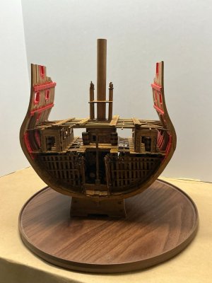
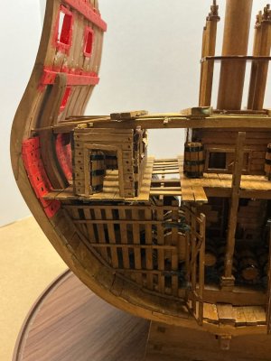
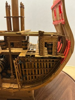
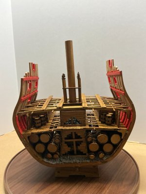
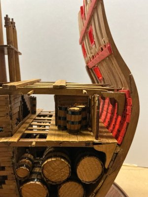
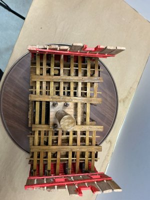
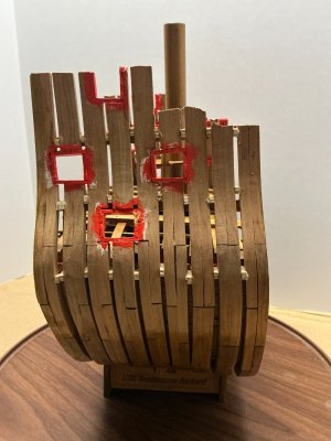
Since my last posting I have completed all the work below Deck 2, the gun deck, including the mast and bilge pumps.
The orlop deck (Deck 3) has been purposedly partially planked as you can see in the photos below. I placed 14 of the small barrels on this deck, most of them inside or around the two storage cabins.
The gun deck support beams and ship knees are in place.
All the new wood, other than listed below, has been treated with the usual wood conditioner, golden oak dye and satin varnish. The orlop and gun deck planking has faux nail heads, one above each support beam and/or ship knee. They are filled as before with Minwax Walnut Wood Fill.
I also framed the insides of the gunport openings and painted them with Model Expo Primer and their Bulwarks/Gun Carriage Red paints.
All comments or questions appreciated.
The orlop deck (Deck 3) has been purposedly partially planked as you can see in the photos below. I placed 14 of the small barrels on this deck, most of them inside or around the two storage cabins.
The gun deck support beams and ship knees are in place.
All the new wood, other than listed below, has been treated with the usual wood conditioner, golden oak dye and satin varnish. The orlop and gun deck planking has faux nail heads, one above each support beam and/or ship knee. They are filled as before with Minwax Walnut Wood Fill.
I also framed the insides of the gunport openings and painted them with Model Expo Primer and their Bulwarks/Gun Carriage Red paints.


All comments or questions appreciated.
Nicely done Henry! Magic Mike


