Thank you Albert !!!Great kit, great skills! She's coming along beautfully. Cheers.
-

Win a Free Custom Engraved Brass Coin!!!
As a way to introduce our brass coins to the community, we will raffle off a free coin during the month of August. Follow link ABOVE for instructions for entering.
-

PRE-ORDER SHIPS IN SCALE TODAY!
The beloved Ships in Scale Magazine is back and charting a new course for 2026!
Discover new skills, new techniques, and new inspirations in every issue.
NOTE THAT OUR FIRST ISSUE WILL BE JAN/FEB 2026
You are using an out of date browser. It may not display this or other websites correctly.
You should upgrade or use an alternative browser.
You should upgrade or use an alternative browser.
Back to the Bonhomme Richard.
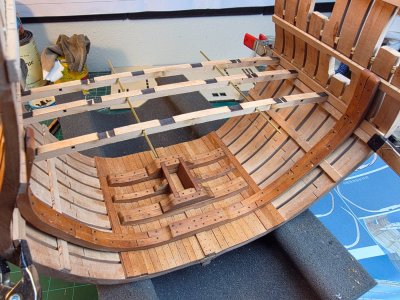
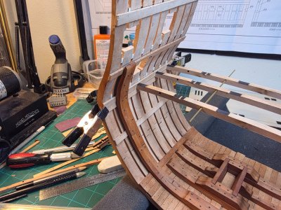
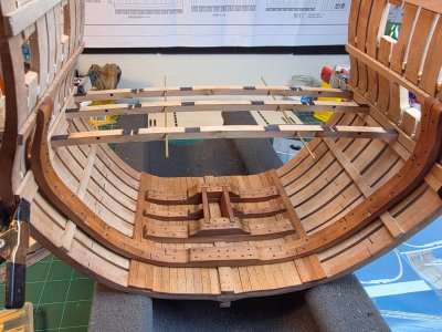
Following the developer indications i have placed 3 out of the 4 beams that goeson deck #2.
The riders and the beans are not glued yet. I still need to understand the structure of this deck and the Orion deck (deck #0 on the kit).
I used brass rods to check the beams alignment and was perfect. The rode aren't part of the kit
Understanding this small step and cleaning the beams took me the full afternoon.
See you all next week !!
Daniel


Last edited:
Good idea checking the alignment!
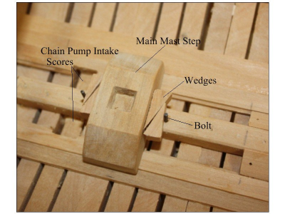
Your build really is looking lovely Daniel. I am really curious about the construction with the five mini riders in the area where the mast would be stepped. The English used a simple block that went across the keelson and was wedged so it could be moved fore and aft to adjust the rake of the mast but I cannot figure out how the mast would be supported and adjusted with the system on an East Indiaman like the Bonhomme Richard. There are a lot of drawings of East Indiamen on the RMG Collections website but I could not find even one that shows how the masts were stepped. Waiting to see how this is worked out. 
Allan
English system - note that there is no strake of planking between the limber strake and keelson on English ships.
Allan
English system - note that there is no strake of planking between the limber strake and keelson on English ships.

- Joined
- Jan 25, 2023
- Messages
- 545
- Points
- 308

The mast rides on the keelson. Wedges were placed fore and aft pointing upwards and then chocks were placed fore and aft to adjust rake. I assume the chocks were placed before the mast is stepped, angle is checked and then, if the angle wasn't correct, they lifted the mast, adjusted the chocks, and lowered it again.
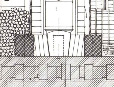

Thanks rtwpsom2, very much appreciated. Do you know the source of this drawing and on what contemporary information it is based? It is very interesting, but I cannot figure out what the screen like boxes and other things are all about. 
Thanks again!
Allan
Thanks again!
Allan
- Joined
- Jan 25, 2023
- Messages
- 545
- Points
- 308

This was taken from the Bonhomme Richard ANCRE drawings. The drawing is a cross section, as if the ship were cut in half along the centerline. The screen shapes are what is known as a hatch. Hatches are used to denote a cut edge (as in you are looking through the material). The screen hatch is the wood material of the main steps, while the spaced lines at 45° are the keel, hogging piece, frames, and keelson. As for the sources used to make the ANCRE drawings, someone else who knows better should be able to say, but from what I have heard ANCRE is very reliable.
Your build really is looking lovely Daniel. I am really curious about the construction with the five mini riders in the area where the mast would be stepped. The English used a simple block that went across the keelson and was wedged so it could be moved fore and aft to adjust the rake of the mast but I cannot figure out how the mast would be supported and adjusted with the system on an East Indiaman like the Bonhomme Richard. There are a lot of drawings of East Indiamen on the RMG Collections website but I could not find even one that shows how the masts were stepped. Waiting to see how this is worked out.
Allan
English system - note that there is no strake of planking between the limber strake and keelson on English ships.
View attachment 535475
The mast rides on the keelson. Wedges were placed fore and aft pointing upwards and then chocks were placed fore and aft to adjust rake. I assume the chocks were placed before the mast is stepped, angle is checked and then, if the angle wasn't correct, they lifted the mast, adjusted the chocks, and lowered it again.
View attachment 535602
Thank you very much to both, for the question and the answer.
To be honest, i am not the guy that can answer does types of questions. I like to built kits, just because i like the outcome and the challenge.
Cheers
Daniel
Finished my first gun port side on deck #2 of the kit. The other side isn't finished yet. Riders not glued.
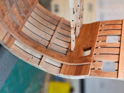
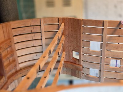
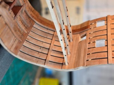
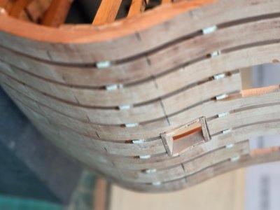
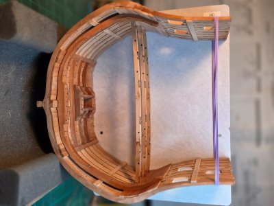
I am sorry that you will have neck pain. I took them as always and I uploaded twice, but still upload in the wrong position.
@Jimsky can you check if the orientation can be changed... thanks you !!
Cheers
Daniel


I am sorry that you will have neck pain. I took them as always and I uploaded twice, but still upload in the wrong position.
@Jimsky can you check if the orientation can be changed... thanks you !!
Cheers
Daniel
Smashing Daniel. Love the nailing and wood colour. Cheers GrantFinished my first gun port side on deck #2 of the kit. The other side isn't finished yet. Riders not glued.
View attachment 536426View attachment 536427View attachment 536428View attachment 536429View attachment 536430
I am sorry that you will have neck pain. I took them as always and I uploaded twice, but still upload in the wrong position.
@Jimsky can you check if the orientation can be changed... thanks you !!
Cheers
Daniel
Thank you !!! ..... but literally I smash a section of the kit.... unglued itSmashing Daniel. Love the nailing and wood colour. Cheers Grant
My mistake tale, that i hope will solve successfully. Will be tell with images.
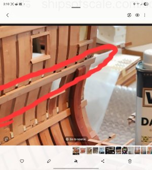
Yesterday night, looking carefully images from @Uwek and @Signet I realized that I did a mistake.
Take a look were the riser ends on this @Signet image (same was at @Uwek built)
This is my built
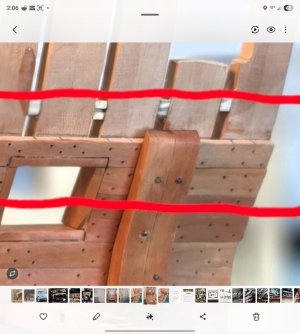
Do you see the differences at the riser tip ? How they ended with the planking.
I was building my BR using also the developer images. At my stage of the built the developer have this image in the instruction manual.
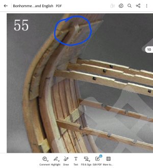
It is exactly as mine.... correct ?
Then I looked for a more advance image of the building process in the instruction manual. And guess what ? The Riser ends now as @Signet riser. See image:
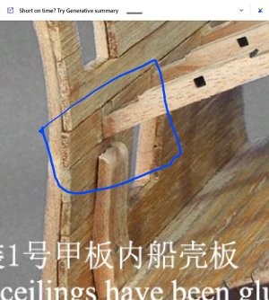
To be followed on next posting
Yesterday night, looking carefully images from @Uwek and @Signet I realized that I did a mistake.
Take a look were the riser ends on this @Signet image (same was at @Uwek built)

This is my built

Do you see the differences at the riser tip ? How they ended with the planking.
I was building my BR using also the developer images. At my stage of the built the developer have this image in the instruction manual.

It is exactly as mine.... correct ?
Then I looked for a more advance image of the building process in the instruction manual. And guess what ? The Riser ends now as @Signet riser. See image:

To be followed on next posting
Last edited:
.... continues..... What the heck was going on with my built ?
I placed the hull over the original drawing of frames #1 , as @Signet did to mark the decks positions. And, unfortunately, I did a mistake on deck #2 beam position. How i did that ??? I don't understand it, as i measured several time the deck position and gun ports positions using the provided developer tool included in the kit.
See image
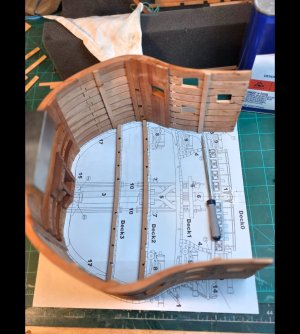
Deck #3 position is correct, but Deck #2 is off for a few millimeters "the diference seen in previous picture on the riser tip and planks). In other words the Deck beam position is lower.
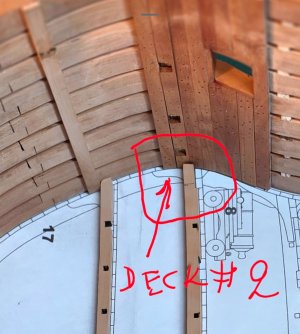
To be continue on next posting....
I placed the hull over the original drawing of frames #1 , as @Signet did to mark the decks positions. And, unfortunately, I did a mistake on deck #2 beam position. How i did that ??? I don't understand it, as i measured several time the deck position and gun ports positions using the provided developer tool included in the kit.
See image

Deck #3 position is correct, but Deck #2 is off for a few millimeters "the diference seen in previous picture on the riser tip and planks). In other words the Deck beam position is lower.

To be continue on next posting....
...... then I though.... what about the gun ports?
Deck #2 (the one with the issue) gun port is a little off , but that has a solution. If the cannon sits high and that looks bad, then I can do these deck ports with the gun door closed. No one will see the mistake. Only YOU GUYS !!! Hahaha
See image: the ruler has the the size of the gun port. And you can check with the drawing that is a little off position.
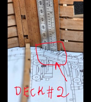
Gun ports for decks #1 and #0 looks fine and also their positions of the decks beams. See tip file for deck #0
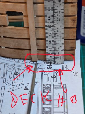
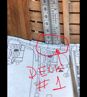
So, what i did for now: I am ungluing deck #2 planking to move the positioning beam up. As you can see below.
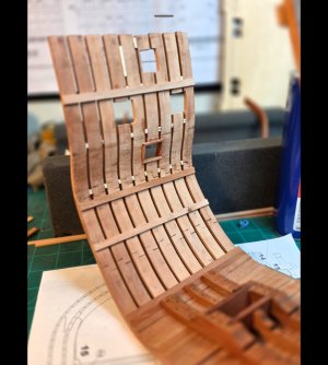
My strategy will be now to work on the internal structures, like Signet and Uwek did and from there i will have a better view of how my decks #3 and #2 are positioned, because those structures need to fit between them.
I hope this tale helps others to avoid my mistake.
Cheers !!
Daniel
Deck #2 (the one with the issue) gun port is a little off , but that has a solution. If the cannon sits high and that looks bad, then I can do these deck ports with the gun door closed. No one will see the mistake. Only YOU GUYS !!! Hahaha
See image: the ruler has the the size of the gun port. And you can check with the drawing that is a little off position.

Gun ports for decks #1 and #0 looks fine and also their positions of the decks beams. See tip file for deck #0


So, what i did for now: I am ungluing deck #2 planking to move the positioning beam up. As you can see below.

My strategy will be now to work on the internal structures, like Signet and Uwek did and from there i will have a better view of how my decks #3 and #2 are positioned, because those structures need to fit between them.
I hope this tale helps others to avoid my mistake.
Cheers !!
Daniel
Last edited:
I noticed in your pictures that the plank that has the cut outs for the deck beans has the slot cut on the bottom of the plank.
If you took that off and flipped it over so the cut out for the beam was on the top, that would put your beam for the deck at about the right level.
I hope that helps !
If you took that off and flipped it over so the cut out for the beam was on the top, that would put your beam for the deck at about the right level.
I hope that helps !
Very smart suggestion !! I will check that option. Thank you !!I noticed in your pictures that the plank that has the cut outs for the deck beans has the slot cut on the bottom of the plank.
If you took that off and flipped it over so the cut out for the beam was on the top, that would put your beam for the deck at about the right level.
I hope that helps !
I just checked against the cross section drawing and it could be a potential solution. Nevertheless, for now, I will not unglue the positioning beam until I check how it fits with the interior construction.I noticed in your pictures that the plank that has the cut outs for the deck beans has the slot cut on the bottom of the plank.
If you took that off and flipped it over so the cut out for the beam was on the top, that would put your beam for the deck at about the right level.
I hope that helps !
Thank you !!
Daniel
Followed your suggestion and worked. See next postingI noticed in your pictures that the plank that has the cut outs for the deck beans has the slot cut on the bottom of the plank.
If you took that off and flipped it over so the cut out for the beam was on the top, that would put your beam for the deck at about the right level.
I hope that helps !


