


Although this in not my first build, it is my first log, so bear with me while I try to figure this out.
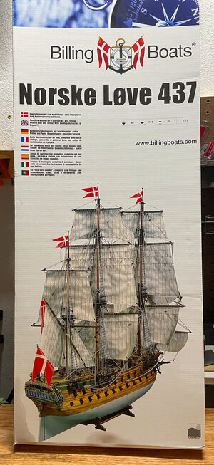
This summer I picked up a Artesana Latina's original San Fransisco kit from the bargain bin in a local hobby shop. I did not have a clue of what to expect. Fortunately I found the experience exciting and challenging. Challenging because the kit came with minimal instructions and Exciting because I enjoy solving problems. Having just completed this build i Ordred th Sphinx from England. Given their production delays I cancelled the order and ordered th Norske Løve insted at half the price. As you will see I am still challeged as the written instructions are still only one page long. Fortunately the illustrations are much better (and more numerous). Also I hope to learn a lot from Dean62's excellent build log.
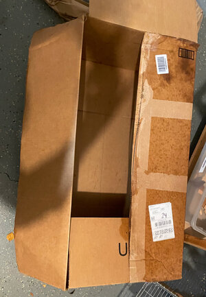
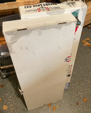
The box containing my new build arrived on Oct 9, 2021.It was raining heavily an the box was soaking wet
.
The inside box was wet as well.

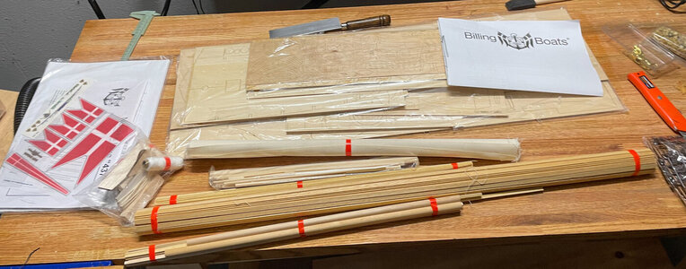
Fortunately the kit was OK

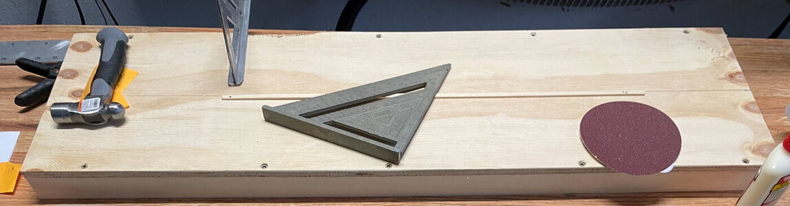
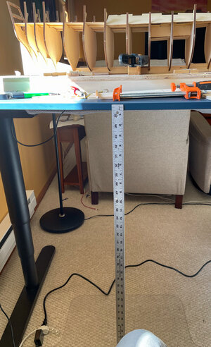
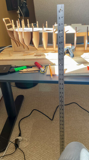
Here are some of the parts I have moved int my tool shed:
This summer I picked up a Artesana Latina's original San Fransisco kit from the bargain bin in a local hobby shop. I did not have a clue of what to expect. Fortunately I found the experience exciting and challenging. Challenging because the kit came with minimal instructions and Exciting because I enjoy solving problems. Having just completed this build i Ordred th Sphinx from England. Given their production delays I cancelled the order and ordered th Norske Løve insted at half the price. As you will see I am still challeged as the written instructions are still only one page long. Fortunately the illustrations are much better (and more numerous). Also I hope to learn a lot from Dean62's excellent build log.
The box containing my new build arrived on Oct 9, 2021.It was raining heavily an the box was soaking wet
.
The inside box was wet as well.
Fortunately the kit was OK
Here are some of the parts I have moved int my tool shed:


")


") Just my opinion….
Just my opinion….