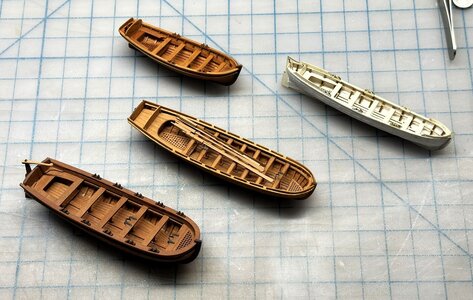
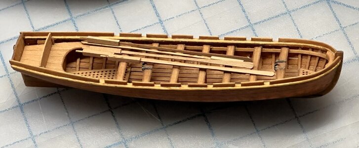
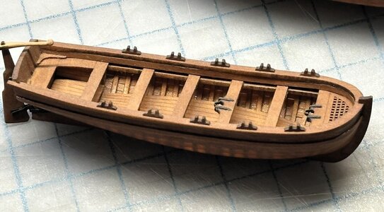
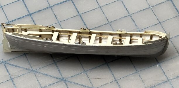
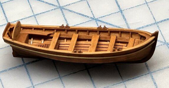
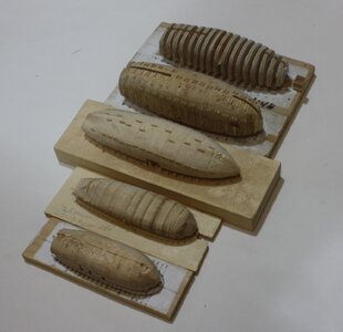
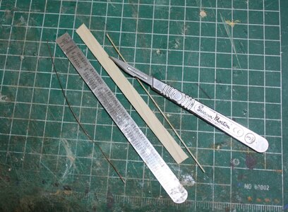
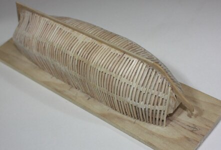
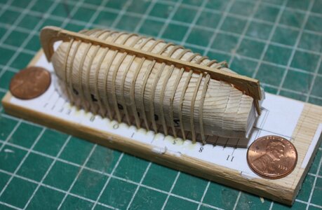
Having seen dozens, or perhaps hundreds, of pictures of ship’s boats models I am convinced there are few if any accurate kits available to us in any scale. I am also convinced most modelers can make an accurate model at our most common scales to replace a kit supplied boat or for a stand alone project. Power tools are a big plus, but hand tools worked for the model makers 300 years ago and still work today. A coping saw, rasps, hobby knife, a hand drill and a few clamps are needed if power tools are not available.
I have made ship’s boats at scales from 1:24 to 1:96, the latter being the more difficult for me due to the smaller scale.
First up is finding a good contemporary drawing. There are many on the RMG Collections website in low resolution, but still useable. https://www.rmg.co.uk/collections/objects/search/ There are also over 5 dozen high resolution drawings on the Wiki Commons site that include barges, gun boats, launches, longboats, yawls, cutters and pinnaces. https://commons.wikimedia.org/wiki/Category:Ship_plans_of_the_Royal_Museums_Greenwich
Once a subject has been selected the drawing can be downloaded and printed. The printed page can be scaled on many home printers or any local print store such as Kinkos or Staples in the US or similar places outside North America.
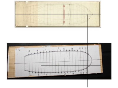
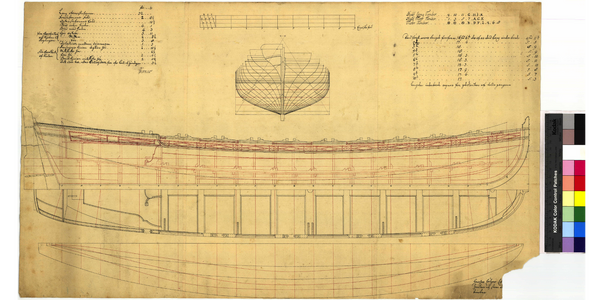
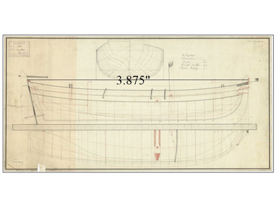
For this project the following is the original drawing I used, a 31 foot longboat of 1801 and building to 1:96 scale. This drawing is available on the Wiki site above in high resolution.
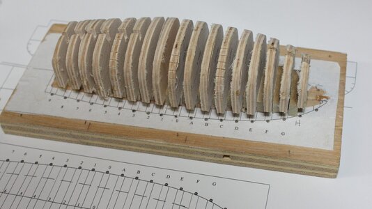
I then used the body plan to create a plug for forming the hull. The drawing of the stations was reduced slightly to account for the thickness of the frames which are moulded 2.75 inches at the futtock heads and 5.25 inches at the floor at the keel so it is a total of 5.5 inches athwartships and 5.25 inches up and down. At our scales the difference is not major.
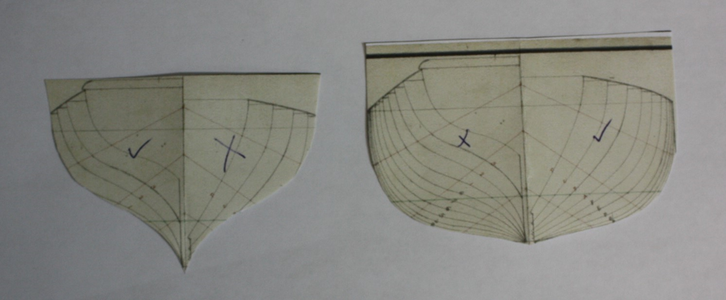
As the plan shows the station lines forward on one side and aft on the other two copies of the plan are needed so a full set can be made for all the stations.
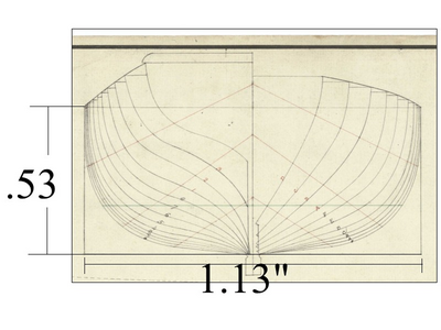
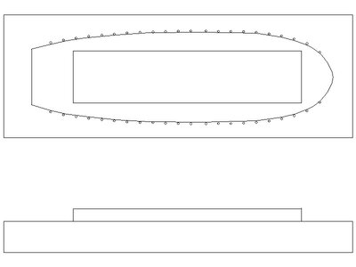
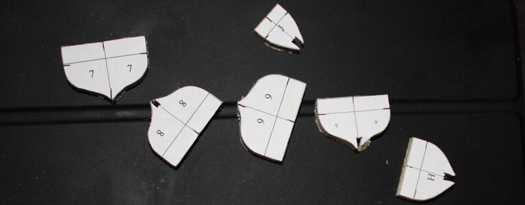
As there are 22 station lines in this case, I copy the full sets so there are multiple copies on a single sheet of paper. I then cut each full set out and fold them on the center line. Once it is folded, cut along the station line chosen and then there is a completed template and then repeat for each station. If you have a drawing program the stations can be copied or traced from the drawing plan and mirror imaged to yield a set of templates in that manner. Mark the station number on each template.
With a drawing program, the results will be similar to the picture below.
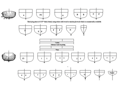
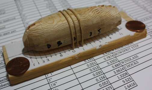
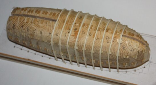
For this particular boat, the room and space is 1’ 3” so at 1:96 I was able to use 4 mm wood for the hull's plug pieces. The overall length was off by 0.4” but this was corrected when sanding the plug after the plug pieces were glued together. For other thicknesses there may not be stock wood sheets of the thickness that is needed so a planer or thickness sander would be needed or laminates of sheets that yields the right thickness will work as well. By the same token slices of the thickness needed can be taken off a block of wood with a hand saw and then the piece traced on the block and cut out with a coping saw or scroll saw if available.
Wood – I prefer holly for the frames but bass wood is more readily available and works well. I like either holly or castello box wood for the planking and thwarts but again basswood, Alaskan cedar, poplar or other more easily found woods can be used. The key is finding sheets of the thicknesses needed or having sheets planed to what is needed. More about this later to show planers and such are nice but not necessary.
For this boat, I used the following scantling chart. There is a chart of scantlings for mid 18th century and circa 1800 in W.E. Mays book, Boats of Men of War, and scantlings of the late 18th century in Scantlings of Royal Navy Ship and in Steel’s Elements and Practice of Naval Architecture, the latter of which can be found as a pdf on line for free. The free version is a little difficult to use. In the first versions mentioned the folios of the scantlings are two pages across as they include a number types and sizes of boat as in the original, but the free copy is single paged so takes a bit of maneuvering to be able to read across.
More to come.
Allan
I have made ship’s boats at scales from 1:24 to 1:96, the latter being the more difficult for me due to the smaller scale.
First up is finding a good contemporary drawing. There are many on the RMG Collections website in low resolution, but still useable. https://www.rmg.co.uk/collections/objects/search/ There are also over 5 dozen high resolution drawings on the Wiki Commons site that include barges, gun boats, launches, longboats, yawls, cutters and pinnaces. https://commons.wikimedia.org/wiki/Category:Ship_plans_of_the_Royal_Museums_Greenwich
Once a subject has been selected the drawing can be downloaded and printed. The printed page can be scaled on many home printers or any local print store such as Kinkos or Staples in the US or similar places outside North America.
For this project the following is the original drawing I used, a 31 foot longboat of 1801 and building to 1:96 scale. This drawing is available on the Wiki site above in high resolution.

I then used the body plan to create a plug for forming the hull. The drawing of the stations was reduced slightly to account for the thickness of the frames which are moulded 2.75 inches at the futtock heads and 5.25 inches at the floor at the keel so it is a total of 5.5 inches athwartships and 5.25 inches up and down. At our scales the difference is not major.
As the plan shows the station lines forward on one side and aft on the other two copies of the plan are needed so a full set can be made for all the stations.

As there are 22 station lines in this case, I copy the full sets so there are multiple copies on a single sheet of paper. I then cut each full set out and fold them on the center line. Once it is folded, cut along the station line chosen and then there is a completed template and then repeat for each station. If you have a drawing program the stations can be copied or traced from the drawing plan and mirror imaged to yield a set of templates in that manner. Mark the station number on each template.

With a drawing program, the results will be similar to the picture below.

For this particular boat, the room and space is 1’ 3” so at 1:96 I was able to use 4 mm wood for the hull's plug pieces. The overall length was off by 0.4” but this was corrected when sanding the plug after the plug pieces were glued together. For other thicknesses there may not be stock wood sheets of the thickness that is needed so a planer or thickness sander would be needed or laminates of sheets that yields the right thickness will work as well. By the same token slices of the thickness needed can be taken off a block of wood with a hand saw and then the piece traced on the block and cut out with a coping saw or scroll saw if available.
Wood – I prefer holly for the frames but bass wood is more readily available and works well. I like either holly or castello box wood for the planking and thwarts but again basswood, Alaskan cedar, poplar or other more easily found woods can be used. The key is finding sheets of the thicknesses needed or having sheets planed to what is needed. More about this later to show planers and such are nice but not necessary.
For this boat, I used the following scantling chart. There is a chart of scantlings for mid 18th century and circa 1800 in W.E. Mays book, Boats of Men of War, and scantlings of the late 18th century in Scantlings of Royal Navy Ship and in Steel’s Elements and Practice of Naval Architecture, the latter of which can be found as a pdf on line for free. The free version is a little difficult to use. In the first versions mentioned the folios of the scantlings are two pages across as they include a number types and sizes of boat as in the original, but the free copy is single paged so takes a bit of maneuvering to be able to read across.
| PARTICULARS, &C. from | LONG BOAT | 1:96 inches | 1:96mm |
| W.E. May, ZAZ5814; and ZAZ7322 | 31 FEET | 3.875 | 98.4 |
| BREADTH Moulded | 9' 6" | 1.19 | 30.226 |
| DEPTH in midships | 4' 3" | 0.531 | 13.5 |
| afore | 5' 6" | 0.688 | 17.47 |
| abaft | 5' 7" | 0.7 | 17.78 |
| KEEL Sided in midships | 5½" | 0.057 | 1.4478 |
| Deep below the rabbet | 6" | 0.0625 | 1.5875 |
| To be above the rabbet for deadwood | 1¼" | 0.013 | 0.3302 |
| STEM Sided | 4½" | 0.047 | 1.1938 |
| Afore the rabbet at the head | 7" | 0.073 | 1.8542 |
| Abaft the rabbet | 1¾" | 0.018 | 0.4572 |
| TRANSOM Broad or moulded at the upper part | 6' 2" | 0.771 | 19.5834 |
| Thick or sided | 3½" | 0.037 | 0.9398 |
| Knees, sided | 3½" | 0.037 | 0.9398 |
| STERN-POST Sided at the tuck | 4¾" | 0.049 | 1.2446 |
| at the keel | 3½" | 0.037 | 0.9398 |
| Broad, or fore and aft at the keel | 1' 4" | 0.167 | 4.2418 |
| (transom included) at the head | 8¼" | 0.086 | 2.1844 |
| ROOM AND SPACE | 1' 3" | 0.156 | 3.9624 |
| FLOOR TIMBERS Sided | 3" | 0.031 | 0.7874 |
| Moulded at the head | 3" | 0.031 | 0.7874 |
| at the throat | 5¼" | 0.055 | 1.397 |
| FUTTOCKS Sided at the heels | 3" | 0.031 | 0.7874 |
| at the heads | 2¾" | 0.029 | 0.7366 |
| Moulded at the heels | 2¾" | 0.029 | 0.7366 |
| Scarph of the timbers | 3' 0" | 0.375 | 9.525 |
| KEELSON Broad | 1' 1" | 0.135 | 3.429 |
| Thick | 3" | 0.031 | 0.7874 |
| FOOTWALING Thick | 1¼" | 0.013 | 0.3302 |
| STEP Broad | 1' 3" | 0.156 | 3.9624 |
| Thick | 5" | 0.052 | 1.3208 |
| Long | 3' 0" | 0.375 | 9.525 |
| RISERS Broad | 10" | 0.104 | 2.6416 |
| Thick | 1¾" | 0.018 | 0.4572 |
| THWARTS Main Broad | 1' 2" | 0.146 | 3.7084 |
| Thick | 4" | 0.042 | 1.0668 |
| After Broad | 8½" | 0.089 | 2.2606 |
| Thick | 2½" | 0.026 | 0.6604 |
| Fore Broad | 9" | 0.094 | 2.3876 |
| Thick | 2¾" | 0.029 | 0.7366 |
| Loose Broad | 8 ½" | 0.089 | 2.2606 |
| Thick | 2" | 0.021 | 0.5334 |
| Knees upon the thwarts, sided | 3" | 0.031 | 0.7874 |
| BENCHES Broad | 1' 0" | 0.125 | 3.175 |
| Thick | 1½" | 0.016 | 0.4064 |
| DEADWOOD Sided | 3½" | 0.036 | 0.9144 |
| BOTTOM Thick | 1⅛" | 0.012 | 0.3048 |
| LANDING STRAKE Broad | 9½" | 0.099 | 2.5146 |
| UPPER STRAKE Broad | 8½" | 0.089 | 2.2606 |
| GUNWALE Deep | 3¾" | 0.039 | 0.9906 |
| Thick | 4" | 0.042 | 1.0668 |
| BREAST HOOK Sided | 3½" | 0.036 | 0.9144 |
| Length | 4' 6" | 0.562 | 14.2748 |
| Moulded at the throat | 7" | 0.073 | 1.8542 |
| EARS Sided | 3¾" | 0.039 | 0.9906 |
| Length | 1' 9" | 0.219 | 5.5626 |
| CHOCKS Thick | 3¾" | 0.039 | 0.9906 |
| Length | 1' 6" | 0.188 | 4.7752 |
| WASHBOARDS Broad Bow Quarter | 7" | 0.073 | 1.8542 |
| BOWSPRIT STEP Thick | 3" | 0.031 | 0.7874 |
| Broad | 1' 2½" | 0.151 | 3.8354 |
| WINDLASS Diameter | 10" | 0.104 | 2.6416 |
| CHOCKS Thick | 6" | 0.063 | 1.6002 |
| Broad | 11" | 0.115 | 2.921 |
| RUDDER Breadth at the heel | 1' 11" | 0.24 | 6.096 |
| Breadth at the hance | 1' 4¼" | 0.169 | 4.2926 |
| Breadth at the head | 9" | 0.094 | 2.3876 |
| Thickness | 1½" | 0.016 | 0.4064 |
| MAST Diameter | 7½" | 0.078 | 1.9812 |
| Length (overall) IF SLOOP RIGGED | 34' 7" | 4.32 | 109.728 |
| SPRIT Diameter | 6¾" | 0.07 | 1.778 |
| Length | 17' 7" | 2.2 | 55.88 |
| BOOM Diameter (tapered to 4" at mast) | 6" | 0.063 | 1.6002 |
| Length | 23' 11" | 3 | 76.2 |
| GAFF Diameter | 3½" | 0.037 | 0.9398 |
| Length | 6 '10" | 0.85 | 21.59 |
More to come.
Allan
Last edited:


