Building a Ship's Boat

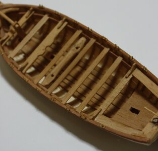
Making and installing the thwarts and benches is an easy task. There was a variation in the thicknesses and widths as mentioned in post #55 above.
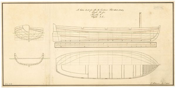
Some were fixed and kneed while others were removable. The contemporary drawings do not always show the knees but those that do seem to be consistent in showing single knees on a forward thwart, aft most thwart and any other thwart against which a mast might rest. Double knees are shown in some cases. There are also some plans with cross sections that show knees, but in the elevations and top views they are not shown as in the first example below, causing some confusion. The cutter plans in post ##58 that Don found is another example. There appears to be knees that are on the sides of the thwarts rather than on top. This was new for me so if anyone has more examples like this that they can share that would be great. Again, many contemporary plans do not show the knees but they were likely there none-the-less, Examples follow:
Knee example 1.jpgKnee example 2.jpg
Knee example 3.png
Knee example 4.JPG
 
Boats mounted on the ships of course had no rigging installed, and I had never bothered with the masts, sprit and lines before this model but thought to just give it a try as there was no ship model on which this longboat was going.

Mast, boom, sprit and line sizes for everything from the painter to the sheets can be found for a range of boat types in David Steels book The Elements and Practice of Rigging and Seamanship. Mast. boom and sprit sizes for sloop and lug rigged boats https://maritime.org/doc/steel/part1.php#pg41

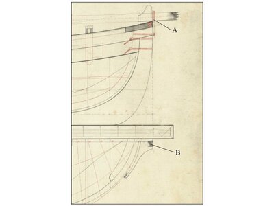
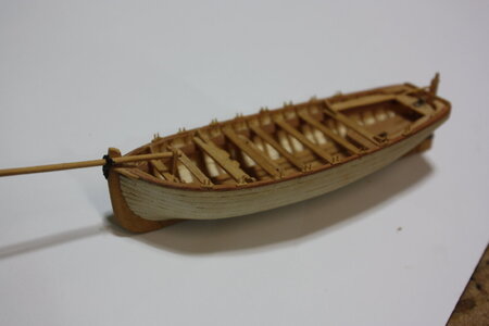
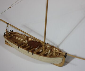
The sprit is set up and secured to the side of the stem and the heel rests in a temporary step that was taken down when the boat was propelled by rowers instead of sail. The support bracket in elevation and from top can be seen in the drawing below and mounted on the model. The step can be seen in the model as well.
Bow details.JPG


IMG_6468.JPG
 
Last edited:
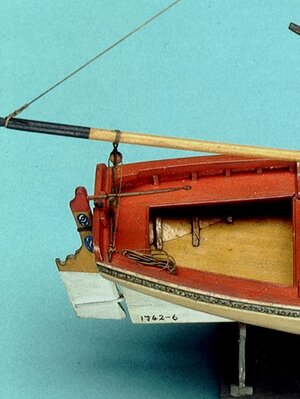
Note in the following photo that the horse is high enough that the tiller can swing underneath it. If the tiller is above the horse the sheet block cannot move along the horse when tacking without hitting the tiller and the tiller cannot be unshipped in the middle of a tack. I do wonder though if this was how things were done. If turning to port for example, the tiller would be hard over to starboard as would the boom and sheet. Same on the opposite tack, so maybe having the sheet block under the height of the tiller was not a problem. In the second photo below the Medway model from 1742 at RMG shows the horse with the tiller above.

IMG_6484.JPG
Medway horse and tiller.jpg

Finding good quality after market blocks in the smallest sizes can be difficult. I was lucky to have some left over from many years ago when Warner Woods West was still in business. If I had not found them I would have had to make my own to get the sizes I needed and at this scale, it would not have been fun.
Allan

IMG_6488.JPG
 
Last edited:
Finding good quality after market blocks in the smallest sizes can be difficult.
Not anymore, today, we have several suppliers with boutique-made rigging blocks. Their (blocks) quality is unique and many members of our forum use them.
I was lucky to have some left over from many years ago when Warner Woods West was still in business.
I am also the lucky guy to have some leftovers. At that time their quality was the best on the market.
If I had not found them I would have had to make my own to get the sizes I needed and at this scale, it would not have been fun.
I agree that making blocks is fun and with your skills, I am sure you can make them nice. What about others? Luckily, today we have a supplier in Canada who has block sizes as small as 2.00 mm high-quality blocks! Don't ya think it is a great news?
 
Thanks Jim
Could you please give a name or two of these suppliers. I had made my own blocks for years but after Warner Woods and then Syren, I lost the incentive to make my own common blocks. Other styles such as clue blocks, sheet blocks, shoe blocks and and some others are generally unavailable so I do still make my own when needed.
Allan
Take a short look at DryDocks - the smallest single blocks are 1,5mm
and in the meantime there are also violineblocks, cleats and other special blocks available
 
THANK YOU JIM! I looked at their site and the blocks indeed look very good.
Thanks, Uwe for the link. In my eyes, they are incredible due to their small sizes. BTW, DryDok caries all common sizes of blocks, and much more fittings. The only problem is, once you buy, you are 'hooked' lifetime unless you make your own. :p
 
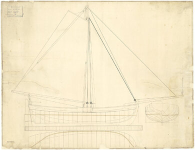
There are not many contemporary plans that I could find for rigging ships' boats. I settled on the following plan for this little build. Note that the tiller goes under the horse in this drawing.
ZAZ7322 Rigged Longboat.jpg
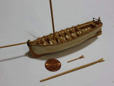
Mast, boom, sprit and rigging started. The straps for the deadeyes are made of copper and blackened with liver of sulfur. At this scale of 1:96 rather than trying to bolt them I epoxied them to the hull as I do not trust CA if any shear forces are put to it. Rigging the blocks and lines is not difficult, but next up is making the deadeyes and rigging the shrouds which I am not looking forward to.
AllanRigging partially done.JPG
 
Last edited:
Hi Anatoly
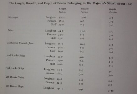
According to Brian Lavery in The Arming and Fitting of English Ships of War, page 212, no 17th century plans of boats have survived. What is known is that 17th century ships carried fewer boats, mainly long boats and pinnaces. They were built "by hand and eye" but I think it is safe to use later drawings to get the basic shape and layouts of frames, thwarts, etc. From G.S. Laird Cloves typical overall boat dimensions can be see here for the mid 17th century. List of boats circa 1640.JPGThe oldest drawing I have found shows boats circa 1700. https://www.rmg.co.uk/collections/objects/rmgc-object-86911

There are mid 18th century drawings in the Danish Archives, RMG, Lavery's book and W.E. Mays' Boats of Men of War. Barring finding information contemporary to the 17th century no one can argue too much if you use drawings from the early or mid 18th century.

Sorry not to be of more help with actual plans.

Allan
 
I was just going through this thread again and when you posted the rigging something started to nag at me. In Vancouver's journal they were going out for two weeks or more with probably 10 men, oars, sails, tents, provisions, swivel gun, small arms and who knows what else in a 22-26 foot boat. Where did they put everything? :)
 
Think about William Bligh leaving with 18 men in a 23 foot launch and sailing 3600 miles before reaching Timor and only losing one man on the way who was killed by natives in Tofua. Plus it had been re-rigged to carry two masts at some point before being set adrift from the Bounty. Talk about close quarters.........
Allan
 
Some random observations to add to Alan’s excellent thread:

I agree with Alan that the boats carried aboard sailing ships were work boats, not lifeboats intended to save the crew if the ship foundered. These were heavy craft and launching them was a major operation. This point is important as form follows function and the hull forms of the different boats reflect the job that they were expected to to do.

When ships began to be equipped with davits, a seaworthy boat, often a cutter, might be designated as a lifeboat. This referred to the boat’s use, not its design. Quickly launched from davits, it could be used to recover a man overboard, not to rescue the crew in the event of a shipwreck.

Longboats and later launches were “jacks of all trades.” Their large internal volume due to their full hull lines meant that in addition to carrying water casks they could also board lots of men for landings and cutting out expeditions. Rigged, they were seaworthy enough to sail on their own. Their full hull lines also gave them the capacity to lift and carry heavy weights. If a sailing ship needed to set out an additional anchor or to move an existing one she required one or more boats to do it. Longboats and launches performed this job.

The method for lifting anchors influenced the design of the boats. In the Eighteenth Century the British Royal Navy lifted anchors over the bow. This meant that their longboats had full lines forward and fine lines aft. The French on the other hand lifted anchors over the stern. Their longboats featured fuller lines aft. Towards the end of the Century the Royal Navy began to favor the launch instead of the longboat. Use of this broad stern craft meant that anchors could be lifted from the stern. Addition of a davit made this job easier.

Later in the Nineteenth Century launches began to be fitted with watertight trunks located midships. These were wooden or copper tubes penetrating the bottom the hull just aft of the windlass. A heavy object, anchor or gun could be carried by suspending it below the boat’s hull.

Ships’ boats make interesting modeling subjects by themselves. The ultimate reference, although later than the fashionable Nelson Era is “The Standard Navy Boats” by Philip Hitchborn. This book details the entire range of the US Navy’s first design of standardized boats in 1900. Prior to that time, boats were designed for each ship or class of ships. The book was reprinted in 1905 and expensive ($250 approx) copies show up on used book sites. The book contains enough information to build or model any of the boats carried on board of the Navy’s Great White Fleet.

Roger
 
Having seen dozens, or perhaps hundreds, of pictures of ship’s boats models I am convinced there are few if any accurate kits available to us in any scale. I am also convinced most modelers can make an accurate model at our most common scales to replace a kit supplied boat or for a stand alone project. Power tools are a big plus, but hand tools worked for the model makers 300 years ago and still work today. A coping saw, rasps, hobby knife, a hand drill and a few clamps are needed if power tools are not available.

I have made ship’s boats at scales from 1:24 to 1:96, the latter being the more difficult for me due to the smaller scale.

First up is finding a good contemporary drawing. There are many on the RMG Collections website in low resolution, but still useable. https://www.rmg.co.uk/collections/objects/search/ There are also over 5 dozen high resolution drawings on the Wiki Commons site that include barges, gun boats, launches, longboats, yawls, cutters and pinnaces. https://commons.wikimedia.org/wiki/Category:Ship_plans_of_the_Royal_Museums_Greenwich

Once a subject has been selected the drawing can be downloaded and printed. The printed page can be scaled on many home printers or any local print store such as Kinkos or Staples in the US or similar places outside North America.

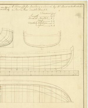
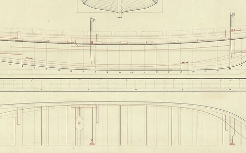
For this project the following is the original drawing I used, a 31 foot longboat of 1801 and building to 1:96 scale. This drawing is available on the Wiki site above in high resolution.

View attachment 450006

I then used the body plan to create a plug for forming the hull. The drawing of the stations was reduced slightly to account for the thickness of the frames which are moulded 2.75 inches at the futtock heads and 5.25 inches at the floor at the keel so it is a total of 5.5 inches athwartships and 5.25 inches up and down. At our scales the difference is not major.

As the plan shows the station lines forward on one side and aft on the other two copies of the plan are needed so a full set can be made for all the stations.

View attachment 450007

As there are 22 station lines in this case, I copy the full sets so there are multiple copies on a single sheet of paper. I then cut each full set out and fold them on the center line. Once it is folded, cut along the station line chosen and then there is a completed template and then repeat for each station. If you have a drawing program the stations can be copied or traced from the drawing plan and mirror imaged to yield a set of templates in that manner. Mark the station number on each template.
View attachment 450008


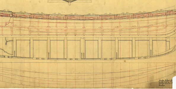
With a drawing program, the results will be similar to the picture below.

View attachment 450009


For this particular boat, the room and space is 1’ 3” so at 1:96 I was able to use 4 mm wood for the hull's plug pieces. The overall length was off by 0.4” but this was corrected when sanding the plug after the plug pieces were glued together. For other thicknesses there may not be stock wood sheets of the thickness that is needed so a planer or thickness sander would be needed or laminates of sheets that yields the right thickness will work as well. By the same token slices of the thickness needed can be taken off a block of wood with a hand saw and then the piece traced on the block and cut out with a coping saw or scroll saw if available.

Wood – I prefer holly for the frames but bass wood is more readily available and works well. I like either holly or castello box wood for the planking and thwarts but again basswood, Alaskan cedar, poplar or other more easily found woods can be used. The key is finding sheets of the thicknesses needed or having sheets planed to what is needed. More about this later to show planers and such are nice but not necessary.

For this boat, I used the following scantling chart. There is a chart of scantlings for mid 18th century and circa 1800 in W.E. Mays book, Boats of Men of War, and scantlings of the late 18th century in Scantlings of Royal Navy Ship and in Steel’s Elements and Practice of Naval Architecture, the latter of which can be found as a pdf on line for free. The free version is a little difficult to use. In the first versions mentioned the folios of the scantlings are two pages across as they include a number types and sizes of boat as in the original, but the free copy is single paged so takes a bit of maneuvering to be able to read across.

PARTICULARS, &C. fromLONG BOAT1:96 inches1:96mm
W.E. May, ZAZ5814; and ZAZ732231 FEET 3.875 98.4
BREADTH Moulded9' 6"
1.19​
30.226​
DEPTH in midships4' 3"
0.531​
13.5​
afore5' 6"
0.688​
17.47​
abaft5' 7"
0.7​
17.78​
KEEL Sided in midships5½"
0.057​
1.4478​
Deep below the rabbet6"
0.0625​
1.5875​
To be above the rabbet for deadwood1¼"
0.013​
0.3302​
STEM Sided4½"
0.047​
1.1938​
Afore the rabbet at the head7"
0.073​
1.8542​
Abaft the rabbet1¾"
0.018​
0.4572​
TRANSOM Broad or moulded at the upper part6' 2"
0.771​
19.5834​
Thick or sided3½"
0.037​
0.9398​
Knees, sided3½"
0.037​
0.9398​
STERN-POST Sided at the tuck4¾"
0.049​
1.2446​
at the keel3½"
0.037​
0.9398​
Broad, or fore and aft at the keel1' 4"
0.167​
4.2418​
(transom included) at the head8¼"
0.086​
2.1844​
ROOM AND SPACE1' 3"
0.156​
3.9624​
FLOOR TIMBERS Sided3"
0.031​
0.7874​
Moulded at the head3"
0.031​
0.7874​
at the throat5¼"
0.055​
1.397​
FUTTOCKS Sided at the heels3"
0.031​
0.7874​
at the heads2¾"
0.029​
0.7366​
Moulded at the heels2¾"
0.029​
0.7366​
Scarph of the timbers3' 0"
0.375​
9.525​
KEELSON Broad1' 1"
0.135​
3.429​
Thick3"
0.031​
0.7874​
FOOTWALING Thick1¼"
0.013​
0.3302​
STEP Broad 1' 3"
0.156​
3.9624​
Thick5"
0.052​
1.3208​
Long3' 0"
0.375​
9.525​
RISERS Broad10"
0.104​
2.6416​
Thick1¾"
0.018​
0.4572​
THWARTS Main Broad1' 2"
0.146​
3.7084​
Thick4"
0.042​
1.0668​
After Broad8½"
0.089​
2.2606​
Thick2½"
0.026​
0.6604​
Fore Broad9"
0.094​
2.3876​
Thick2¾"
0.029​
0.7366​
Loose Broad8 ½"
0.089​
2.2606​
Thick2"
0.021​
0.5334​
Knees upon the thwarts, sided3"
0.031​
0.7874​
BENCHES Broad1' 0"
0.125​
3.175​
Thick1½"
0.016​
0.4064​
DEADWOOD Sided3½"
0.036​
0.9144​
BOTTOM Thick1⅛"
0.012​
0.3048​
LANDING STRAKE Broad9½"
0.099​
2.5146​
UPPER STRAKE Broad8½"
0.089​
2.2606​
GUNWALE Deep3¾"
0.039​
0.9906​
Thick4"
0.042​
1.0668​
BREAST HOOK Sided3½"
0.036​
0.9144​
Length4' 6"
0.562​
14.2748​
Moulded at the throat7"
0.073​
1.8542​
EARS Sided3¾"
0.039​
0.9906​
Length1' 9"
0.219​
5.5626​
CHOCKS Thick3¾"
0.039​
0.9906​
Length1' 6"
0.188​
4.7752​
WASHBOARDS Broad Bow Quarter7"
0.073​
1.8542​
BOWSPRIT STEP Thick3"
0.031​
0.7874​
Broad1' 2½"
0.151​
3.8354​
WINDLASS Diameter10"
0.104​
2.6416​
CHOCKS Thick6"
0.063​
1.6002​
Broad11"
0.115​
2.921​
RUDDER Breadth at the heel1' 11"
0.24​
6.096​
Breadth at the hance1' 4¼"
0.169​
4.2926​
Breadth at the head9"
0.094​
2.3876​
Thickness1½"
0.016​
0.4064​
MAST Diameter7½"
0.078​
1.9812​
Length (overall) IF SLOOP RIGGED 34' 7"
4.32​
109.728​
SPRIT Diameter6¾"
0.07​
1.778​
Length 17' 7"
2.2​
55.88​
BOOM Diameter (tapered to 4" at mast)6"
0.063​
1.6002​
Length 23' 11"
3​
76.2​
GAFF Diameter 3½"
0.037​
0.9398​
Length 6 '10"
0.85​
21.59​

More to come.
Allan
Fantastic work Allan!!
 
Back
Top