Hi All
Those that follow my builds will know the why's and wherefores as to why I have decided to start this build.
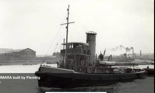
Caldercraft's kit has been around for a while now and builds into a stunning model having originally been designed by the late Frank Hinchcliffe who subsequently went on to start Mountfleet models. I will be making one or two small tweaks to a standard build, some cosmetic and some out of necessity to allow access to the steam plant.
The kit is available in prototypical twin screw or single screw design to make Steam power easier.
I have bought the single screw kit to leave my options open to how to power the model. After two months of research and measuring I have decided to go with two steam engines powering twin screws.
Chosen for their compactness and torque, I have opted for two PM research NO 8 Vee Twin oscillating engines. These economical units have a lot of praise for their quality but budget price. I did initially want to go for something more exotic but that would not work with the space available.
Just this morning, I have had a long discussion with Nigel@ Pendlesteam boilers and I am ordering a twin burner 5 inch boiler to power these two engines. He makes his boilers to order and I am looking at around a one month lead time for this. Nigel was extremely helpful in guiding me as to what I should and should not be going for initially.The two engines being 1/2" Bore and 3/4" Stroke mean I have the ability to consume lots of steam and higher revs will empty the boiler very quickly. Fortunately the propellers will be 85mm diameter meaning the RPM will be very low increasing run time of the model between boiler fills.
I will be using disposable Butane/Propane mix gas cartridges to fuel the boiler rather than a custom refillable gas tank as these are more convenient and hold more capacity that the proprietary model tanks.
Nigel has advised me not to fit an on board water tank and handpump initially (to replenish water in the boiler) as I may find I have sufficient boiler capacity for a reasonable run time rather than overcomplicating the installation.
I will be covering the steam plant in great depth once I have all the components, but for now I will do what I can to the hull whilst my boiler is being made.
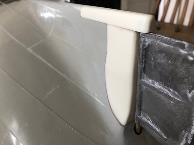
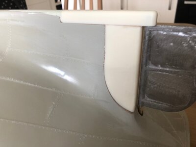
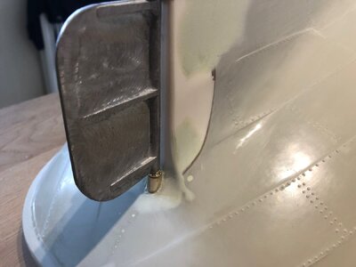
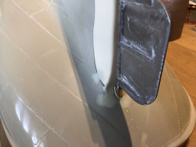
Now given that the kit was designed for single screw in my case, I need to fill the prop cutout in the hull as it is no longer required.
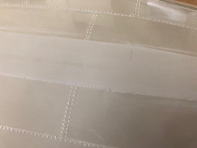
Fortunately, it is that simple, the hull lines are identical to the twin screw kit so it is just that, a case of filling the void at the end of the keel and fairing to the hull and then reinstating plating and riveting.
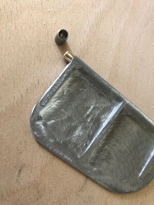
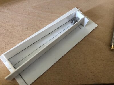
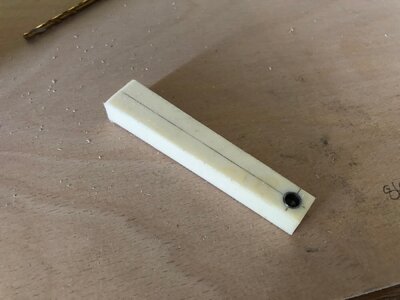
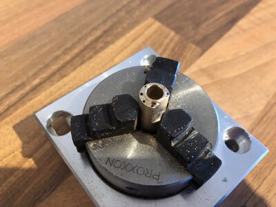
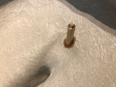
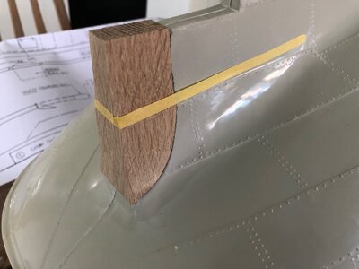
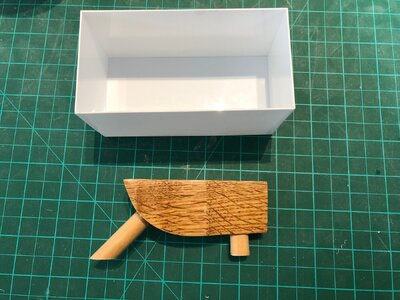
To do this I made a slightly oversize pattern from Oak and added two dowels, one for filling a one as a vent. This unit received eight coats of varnish, sanding between coats, to prevent the silicon moulding rubber from sticking.
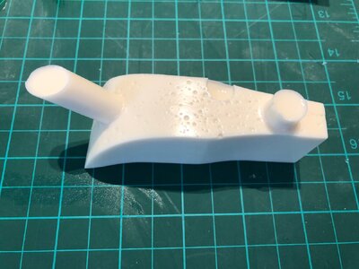
The piece was then used to make a silicon rubber mould so I could cast the block in polyurethane casting resin.
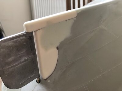
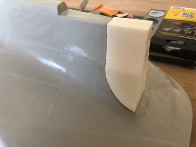
The cast block was then glued to the hull using Stabilit express two part adhesive. This glue is far superior to Epoxy but is hard to get hold of. I now have to buy this on Ebay.
The block will require substantial shaping then the hull detail replacing which I will cover later.
Kind Regards
Nigel


