Caldercraft-Imara 1/32- RC with twin steam engines

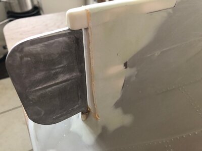
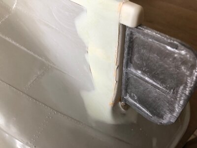
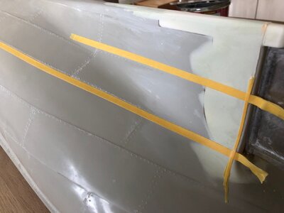
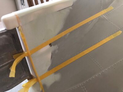
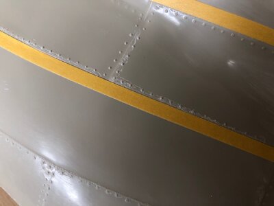
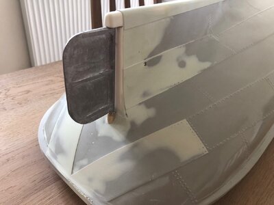
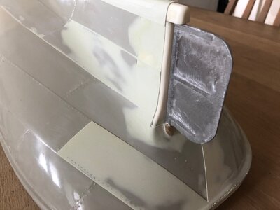
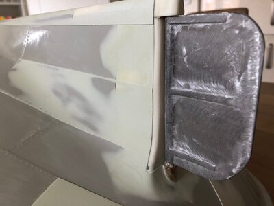
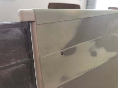
I have starting reinstating the plating lines using car body filler.

I first outlined the edge of the plating where it met the sternpost and applied a thin layer of filler and faired back.

The overlapping plates are then outlined with further layers of tape to apply another layer to simulate the raised plates. I have gone further up one side as the last picture shows spalling in the gelcoat. This will be repaired and rivets reinstated.

As always a picture says a thousand words so I won't waffle on.

Kind Regards

Nigel

IMG_0848.jpgIMG_0849.jpgIMG_0850.jpgIMG_0851.jpgIMG_0852.jpgIMG_0853.jpgIMG_0854.jpg
 
Great info Nigel.
To me this is the most fascinating r/c model ever.
I hunted my on EBay and got it for $250.00. Great deal.
So far I made a wooden base for it and will post soon a picture of how I made it.
Do you have any idea of how much ballast this big model will need?.
Looking forward to se your posts.
I will be your number one follower.
Can’t wait to learn from your skills.

Take care
Julian

Like I said, I have read the model weighs in between 42 and 44lb to get down to the waterline. How much ballast depends on many variables, batteries, running hardware etc.

Kind Regards

Nigel
 
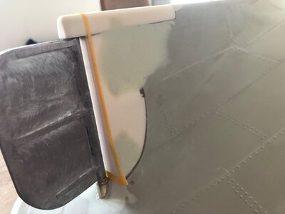
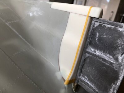
I have completed the plating detail reinstatement to the stern. There is an angle to form below the "belt" at the stern but I am currently sorting the mould joint line in the bulwark at the stern so will revisit this detail soon.

Kind Regards

Nigel

IMG_0855.jpgIMG_0856.jpgIMG_0857.jpgIMG_0858.jpg
 
G'day Nigel, I will take a seat also, I know how meticulous you are with your models and this one will be absolutely superb in your hands, i built one approx7 years ago but it was built from the box with only a few modifications, she is a fantastic kit to build, I have a part build log on here but I lost a lot of it when I was on MSW when the site crashed, I look forward to your rendition,

best regards john,

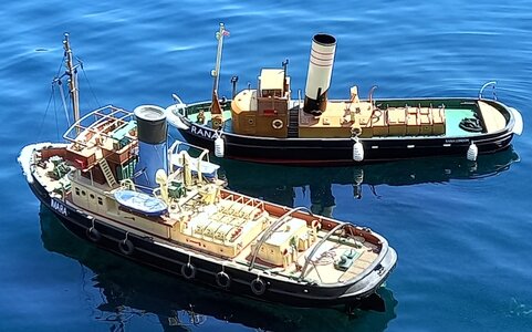
PS here is a pic of her on the water, with another tug I scratch built,

307.jpg
 
Thanks Guys:)

I had a look at your log John, I don't think I have the patience to sit down a clean all the castings up in one go like you did, I feel it will be as and when required:oops:

Your build turned out great and the colour scheme you have chosen is similar to what I have in mind. I don't like the stark white superstructure and orange decks depicted on the box.

One step backwards for the kit IMHO is the deck overlay is no longer printed but laser etched instead.I doubt I will use these as I feel the planking lines are nearly invisible.

One gripe with the kit, no decals supplied for the lettering :(

Kind Regards

Nigel
 
Thanks Uwe

Now there is a "double whammy" to this project.

Originally I had intended to make the complete steam plant from scratch for this model and obtained drawings for a small plant. I also obtained a book which covered making the engine in brief detail.

The engine was of a Vee Four design with 8mm bore by 13mm stroke. My intention was a single propeller to drive the model.

Two things bothered me with this design, firstly this was not prototypical and secondly the stern post is so wide, half the 65mm prop, the largest that would fit, would be half covered by the post.

I considered two of these engines on twin props but the maximum prop size for this Vee Four is @65mm, far smaller than the prototypical scale size of 85mm diameter.

The drawing package I received covered EVERYTHING for the Steam plant including the boiler. I did some research into the "red tape" of DIY boilers in the UK. This is a legislation nightmare as it is a pressure vessel and you must have a test certificate if you take the model out in public. This also needs retesting every two years. I could set a simple rig up to pressure test the boiler with water as the pros do it as it is the same system for testing central heating systems, however I am not qualified to produce the certificate.

So where am I going with this, well despite purchasing the two PM research engine kits which I will build soon ( I have been waiting on a tap for the steam inlet and exhaust) I am still going to build the engine I have drawings for. I had priced up the additional tooling and materials to build this engine, the outlay makes it unviable for one engine so I am going to build several ROTF Four is the figure in my head at the moment. It gives me the option to sell a couple if I so choose.

A comment by Paul AKA docknatter as to some people having the ability to machine metal parts has encouraged me a little with this. I will be doing a build log for these engines in the "lathe, mill etc" section and will try to cover all aspects of the work.I will also be using some "mass production" techniques as I am building more than one engine.

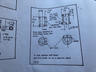
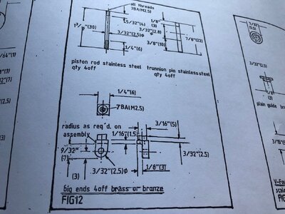
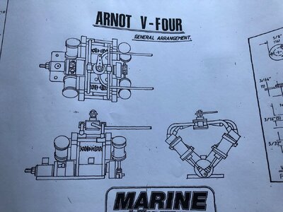
The engine was designed by Peter Arnot, a very talented model engineer and was featured in a long run of articles in Model Boats magazine back in 1993. I suspect that Peter may no longer be with us but I haven't been able to confirm this. The engine is a four cylinder double acting Oscillator engine with RC controllable reversing valve

Marine Modelling Magazine who published the Plans sadly are long gone. Fortunately these are available now from Sark Hobbies in the UK. The drawings are over two massive sheets with individual drawings for every part including boiler, valves and even a crankshaft driven water pump which I will also be making.

This is a complete sideline to Imara and is more about the challenge of making my own engine from scratch. I have the option if I choose to mount one ore more of these engines in a future model if I so chose.

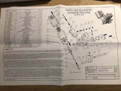
I include a small snippet of the drawings to give you an idea of what I am dealing with, but not enough to get me into copyright bother.

Kind Regards

Nigel
IMG_0861.jpgIMG_0862.jpgIMG_0863.jpg
 
Last edited:
Back to the motive power for this build....

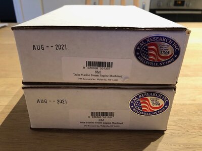
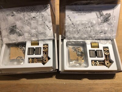
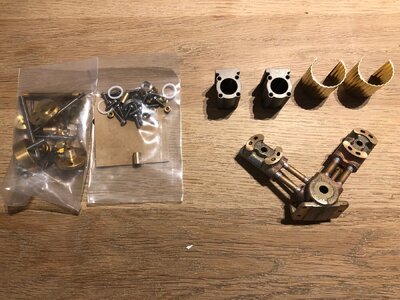
These are the two PM research machined kits I am using. Each vee twin engine has a 13mm bore with 20mm stroke giving me a total of 10.6cc capacity across all four cylinders, plenty of power but the 20mm stroke will give me loads of torque at low revs. Doubtful these unfits will need to rev much beyond 5-600rpm.

These units also contain an integral rc actuated throttle/reversing valve meaning full control using one servo per engine.Both engines will be independently controllable giving me "tank steering" when needed.

Kind Regards

Nigel

IMG_0864.jpgIMG_0865.jpgIMG_0866.jpgIMG_0867.jpg
 
Whilst I may never use the rudder on this model as the engines will provide steering, I have chosen to make it functional.

I made the rudder tube higher than that shown in the plan. The principle being that the open end is above the waterline to reduce water ingress.

My rudder finishes just below deck level so the deck beams will be in the way of the servo pushrods. I have machined a tiller arm out of 3/4" by 3/8" brass stock. This moves the pushrods lower down. The arm is tapped to take an M3 grubscrew. Holes and final shaping of the "ears " will be done when I finalise the double arm going on the servo.

Kind Regards

Nigel

IMG_0868.jpgIMG_0869.jpgIMG_0871.jpg
 
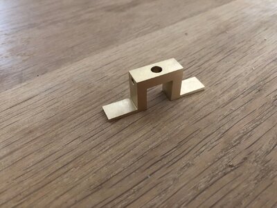
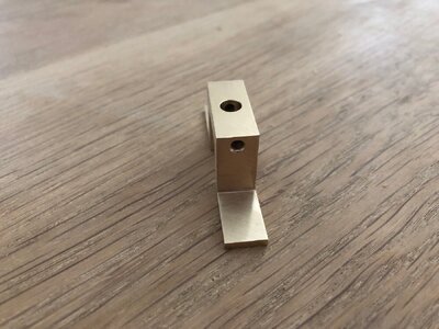
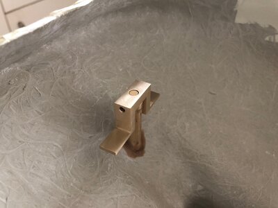
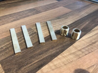
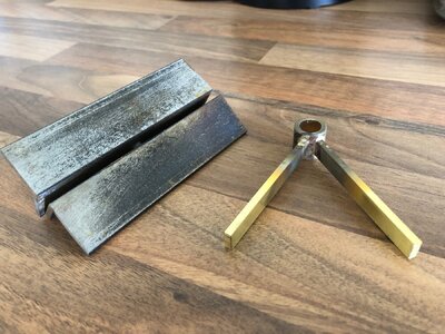
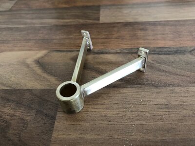
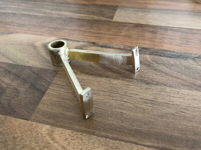
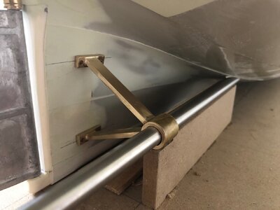
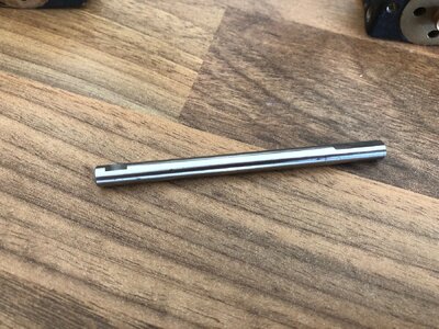
It was now time to start on the drivetrain. I made a simple jig using an mdf board and supports to mock up where the propshafts go. After cutting the holes in the hull I needed to fabricate some A brackets to take the shafts. Had I bought the twin screw kit, I would have white metal castings for these but I feel my home-brew ones will be stronger.

I machined the bosses on the lathe and added pockets for the supports to locate using the MF70 mill.Only light cuts as that machine isn't really cut out for Brass.

The two arms and boss are Silver soldered together with the fixture in the picture clamping the two arms at the correct angle.

After much trial fitting the A frame is trimmed to length and Brass "feet" silver soldered on. The holes will take dummy bolts that will be epoxied into the hull for strength.

The last picture shows the first frame mocked up in position in the jig. The Stainless tube is overlong and is only for locating purposes ROTF

IMG_0872.jpgIMG_0873.jpgIMG_0874.jpgIMG_0875.jpgIMG_0876.jpg
 
Thanks John

Yes they are the real deal and surprisingly good value for something not coming from China.

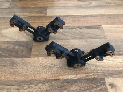
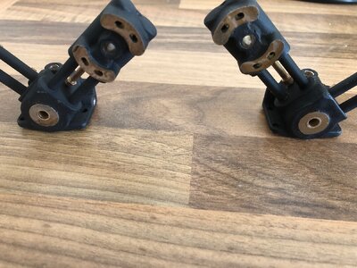
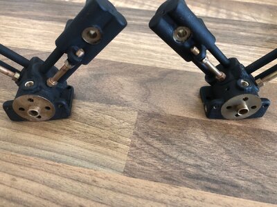
Last weekend I did the preliminary work on the two engines. I fettled the castings then painstakingly masked all the mating faces, inlet, exhaust and tiny oily holes.

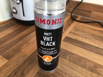
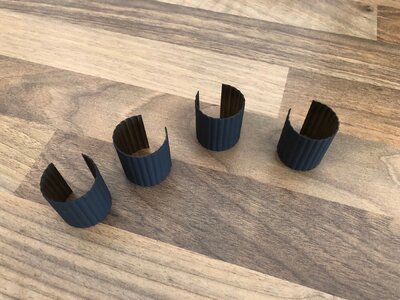
The two engine blocks and brass cylinder covers were then sprayed with the VHT paint pictured. This is a heat cure product so the items went into the kitchen ELECTRIC oven for 90 minutes, gradually increasing the temperature up to a maximum of 180 degrees C.

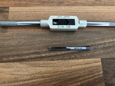
The Engines' inlet and exhaust are threaded 3/16" x 40 tapered thread to suit PM Research tapered thread pipework which I did not wish to use. These threads were tapped out 3/16" x 40 ME parallel threads to suit my planned plumbing. Next task is to machine 4 tiny adapters out of brass hex bar.These will screw into the engine blocks and allow me to fit a 1/4" x 40 ME union nut to carry the 5/32" copper pipework.I had purchased 3/16" unions and pipe but feel the bore is far too restrictive to supply adequate flow of steam and the performance may have suffered.

One lesson learned though, allow the VHT paint to air dry, remove masking, then bake. I spent hours cleaning the masking's adhesive off with isopropyl alcohol:mad:

Kind Regards

Nigel

IMG_0878.jpgIMG_0879.jpgIMG_0880.jpgIMG_0881.jpg
 
Thanks Stephen. I hope the finish turns out to be reasonably durable, spent some time looking at different products.

Next step was to fit the bronze bearing sleeves into the crankcase. Instructions call for a press but my large mill vice worked just fine. It is more precise and has smooth jaws as opposed to my bench vice.

The flush fit sleeves went in first then the sleeves on the valve end second as these protrude 1/8". I had tried the crankshaft in the sleeves before fitting and it was a lovely smooth fit but it will not fit now. To be fair, it does state in the instructions that the sleeves may need reaming after installation. I would go as far as to say they WILL need reaming.

There is a video on YouTube with two launches both using these engines. The video does show the benefits of changing to ball races as the launch without ball races requires triple the steam pressure. I suspect that this is due to the builder not reaming the bearings and the engine is far too tight.

I did buy ball races but I feel the lubrication will be lost as I cannot get sealed ball races in this size.The engine is designed to have a wet crankcase and has an oiling port. I just feel oil will run straight through to the bottom of the hull.

Anyway, I have ordered a 3/16" hand reamer but do plan on supporting the engines in the mill to ensure the finished result is true using hand power only.

IMG_0882.jpgIMG_0883.jpgIMG_0884.jpg
 
Back
Top