When does the part I might understand begin  ?
?
 ?
? |
As a way to introduce our brass coins to the community, we will raffle off a free coin during the month of August. Follow link ABOVE for instructions for entering. |
 |
 |
The beloved Ships in Scale Magazine is back and charting a new course for 2026! Discover new skills, new techniques, and new inspirations in every issue. NOTE THAT OUR FIRST ISSUE WILL BE JAN/FEB 2026 |
 |
 ?
?At the same moment that i start understanding Paul.When does the part I might understand begin?
"You had one job to do..."Seems like they got the house number right, just the wrong street!


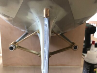
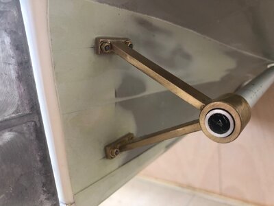
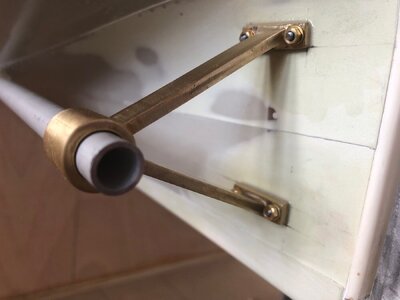
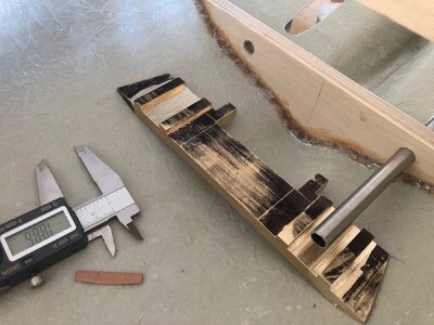
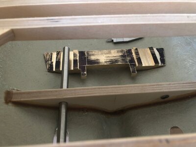
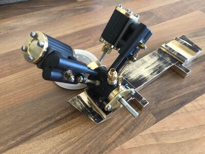
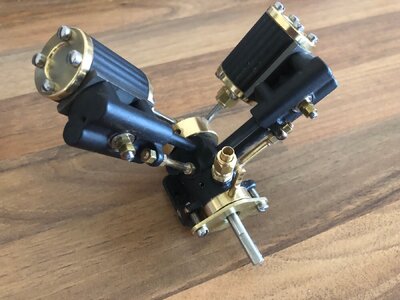
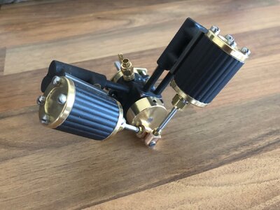
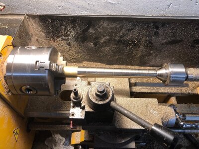
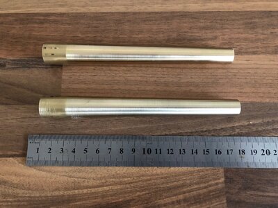
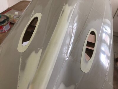
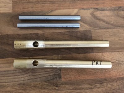
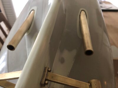
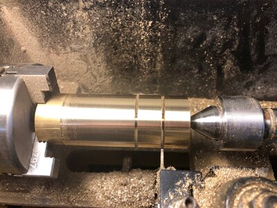
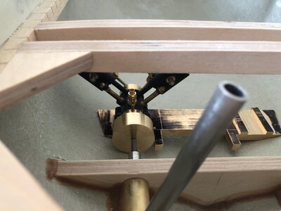
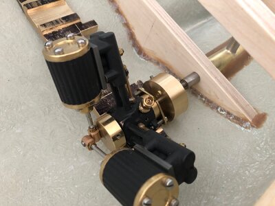
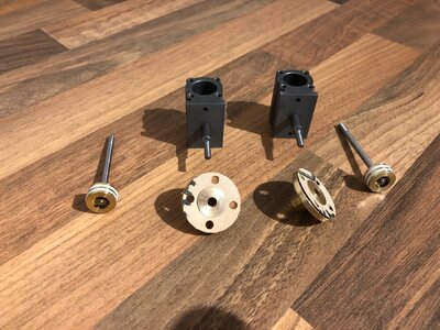
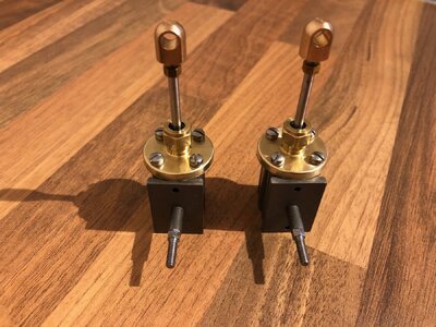
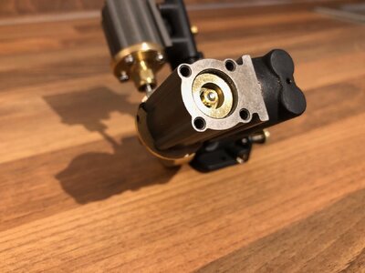
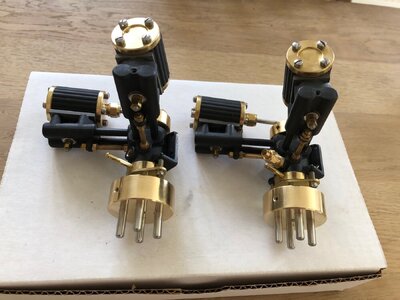

I have had a weekend focusing on motive power including building up the second engine.
I firstly turned some 40mm diameter solid bar to make two flywheels. These each have 4 stainless pins locktited in to create drive dogs. There was no why I would be able to access Allen screws in universal joints with the throttle servos in place and I wanted to make the engines easy to remove for any maintenance.
Two of the pictures illustrate how close the flywheel comes to the inside of the hull. This is the worst side due to the Asymetry in the hull shape.
The sequence of pictures show the second engine being built. One point to note for anyone building these is to ensure the piston moves freely once installed with the bottom cylinder cover. Two of the four did bind at the bottom of the stroke. Unscrewing and refitting the bottom cover after turning the cover 180 degrees solved this and is covered in the instructions. The other important thing is to ensure 1/16" clearance between the piston crown and cylinder top at TDC.This is accomplished by the adjustable big end bearings.
Other than the initial paint and prep, the most time consuming part of building these engines was cutting out the gaskets out of the supplied sheet of raw material
Last picture shows both engines assembled with my home-brew flywheels. I just have to finish the rest of the inlet and exhaust pipe adapters to complete
View attachment 457969View attachment 457970View attachment 457971View attachment 457972View attachment 457973View attachment 457974View attachment 457975

Good morning Nigel. So cool. Now you are working with a zero tolerance- respect. Cheers GrantI have had a weekend focusing on motive power including building up the second engine.
I firstly turned some 40mm diameter solid bar to make two flywheels. These each have 4 stainless pins locktited in to create drive dogs. There was no why I would be able to access Allen screws in universal joints with the throttle servos in place and I wanted to make the engines easy to remove for any maintenance.
Two of the pictures illustrate how close the flywheel comes to the inside of the hull. This is the worst side due to the Asymetry in the hull shape.
The sequence of pictures show the second engine being built. One point to note for anyone building these is to ensure the piston moves freely once installed with the bottom cylinder cover. Two of the four did bind at the bottom of the stroke. Unscrewing and refitting the bottom cover after turning the cover 180 degrees solved this and is covered in the instructions. The other important thing is to ensure 1/16" clearance between the piston crown and cylinder top at TDC.This is accomplished by the adjustable big end bearings.
Other than the initial paint and prep, the most time consuming part of building these engines was cutting out the gaskets out of the supplied sheet of raw material
Last picture shows both engines assembled with my home-brew flywheels. I just have to finish the rest of the inlet and exhaust pipe adapters to complete
View attachment 457969View attachment 457970View attachment 457971View attachment 457972View attachment 457973View attachment 457974View attachment 457975
