• LUCZORAMA SHIPWRECK SCAVENGER HUNT GIVEAWAY. 4 Weeks of Fun • 1 Legendary Prize ((OcCre’s Fram Ship)) • Global Crew Welcome!
    **VIEW THREAD HERE**

Caldercraft-Imara 1/32- RC with twin steam engines

Hi Nigel,

Coming along very nicely.
Do you intend to rely on the pipe work to support the displacement lubricators and globe valves or is there going to be some sort of support for that assembly?

Cheers,
Stephen.
Thanks Stephen

In answer to your question, now I have the two pipes made up and in position, yes.

I had decided to see how rigid it was when all together before committing to bracketry.

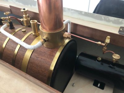
It is pretty solid now before I lag the pipes. Lagging with string, soaking the lagging with thin CA then finally enamel paint makes for really sturdy steam lines
 
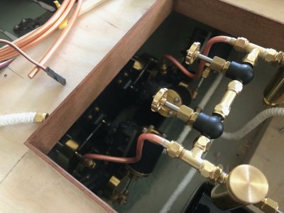
The two steam feed pipes have been made up and temporarily fitted. These will be lagged as the rest of the steam pipes

IMG_2652.jpg

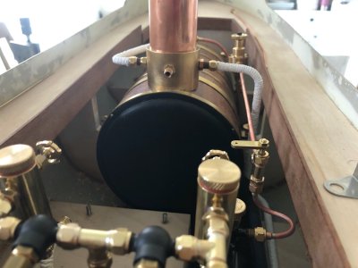
The remaining gas pipes have been made up and fitted

IMG_2653.jpg

Things are very snug but there is clearance between gas pipe and boiler pipe. Thankfully the gas pipe will not be lagged

IMG_2654.jpg

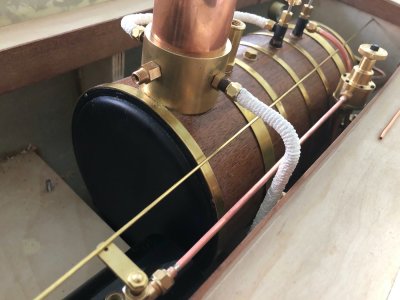
The brass rod in the picture is a mockup of where the servo pushrod will run from the gas shut off valve and a servo mounted to the forward bulkhead. Like I say, all very tight but doable

IMG_2655.jpg
 
My career was spent fabricating piping systems for power plants; aka pipework in Great Britain. I enjoyed learning the surprisingly complex technology involved in engineering these huge assemblies. I once made a trip to Ations’ in Darbyshire to compare British piping technology with ours. They had a segment of the main steam pipe from the destroyer HMS Cossack in their lobby. The pipe had been pierced by a German shell while Cossack was rescuing prisoners captured by the German Pocket Battleship Graf Spee. The purpose of the trip was to to determine if we could work together on a project. We could not; the BSA standards were completely different from our ASME code.

A problem with piping carrying high temperature steam is to control thermal expansion. Connections to boilers and turbines anre areas of particular concern. With relatively fragile connections at the boiler and engine, is this a concern for you?

Roger

Hi Roger, a valid point which is why I have refrained from locking pipe work in place with brackets. All steam lines are only fixed at their ends and none are straight. Bends give the pipe runs some compliance to allow for expansion and contraction

The 1/4 x 40 pipe fittings are rated for superheated steam and pressures higher than my 60 psi limit on the boiler safety valve. I know all fittings should ideally be bronze to prevent dezincification but brass is deemed enough on models that spend a limited time of their life running
 
A little update to show I am still alive and working on the modelROTF

My original intention of getting the model running for the Kirklees steam open day got diverted as I hadn't reviewed the missing screw for one of my engines so I stripped everything out of the hull and I am focusing on finishing the hull before the engine boiler etc go back in. They can then stay in place whilst I work on the superstructure.

I have since sourced some replacement bolts for both engines as these are Allen head as opposed to the kit supplied Cheesehead screws. They are also Stainless and I am unsure that the PM Research screws are not just Bright Zinc Plated.

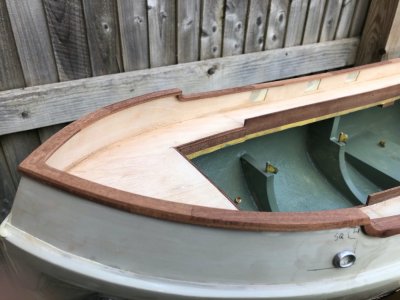
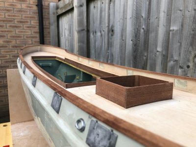
I have focused work on the Bulwarks and capping rail.

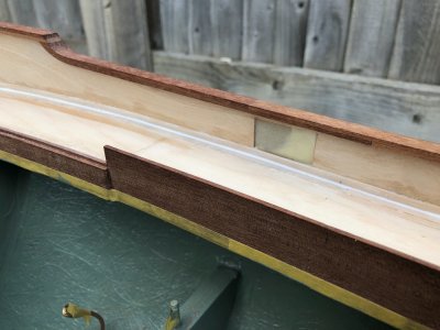
I elected to not cut holes for the scuppers but instead lined the Bulwarks inside with 0.8mm ply with cutouts where the scuppers are. this creates the illusion of scuppers without weakening the hull and also gives me a larger glue area for the cast metal kit scupper doors.

The Hawse hole surrounds have been added on the outside. The holes will be opened up in the middle of the castings then similar castings epoxied to the inside.

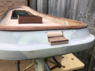
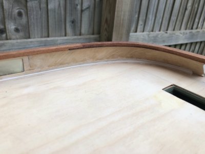
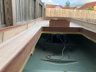
I have replaced the kit ply capping with two layers of 2mm Mahogany cut from sheet with overlapping joints between the layers.These will be finished in varnish and not painted black. maybe a little artistic license but I would argue these are timber on the original, not steel.I had intended to use Pear but felt Pear would look to much like a piece of furniture, not a working boat.

The little "window" on the stern is for cable to pass through to a steam windlass. The drawings are a little vague in this area and I have seen at least one model built incorrectly. No cut out, just a shelf with the cable roller guides sat on it.The cutout is not shown on the top elevation but is shown in the stern cross section. Any future builders take note. This detail is work in progress and lots more work to do in this area plus there will be a lot of detail added to the inside of the Bulwarks beyond what is supplied in the kit
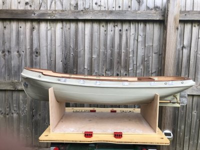
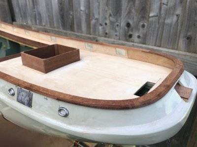
IMG_2673.jpgIMG_2674.jpgIMG_2675.jpgIMG_2677.jpgIMG_2678.jpg
 
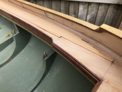
Not masses to show but the first stage of inner Bulwark super detailing has been completed.

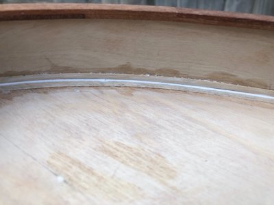
There should be angle irons inside and outside if the Bulwark on steel ships of this period sandwiching the plating of the bulwarks. They are detailed on the hull moulding outside but no detail provided inside.

Interestingly, the Late Frank Hinchcliffe, founder of Caldercraft, did not include this detail when he designed this kit but these angles are provided as white metal castings in the kits he produced when he ran Mountfleet models.

I have spiled the "legs" of the angles from 0.4mm Birch ply and interior filler has been used to provide the internal radius. I used interior filler as the fillet is easy to shape with a wetted small Tamiya q Tip

A surprising amount of work due to all the card templates I had to make and the fragility of the narrow sections of very thin ply. Further details will at least be straight:D

IMG_2680.jpgIMG_2681.jpgIMG_2682.jpgIMG_2683.jpg
 
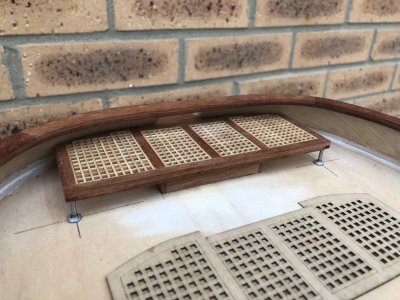
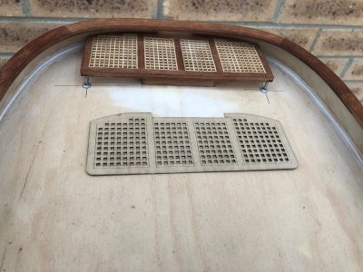
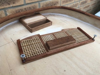
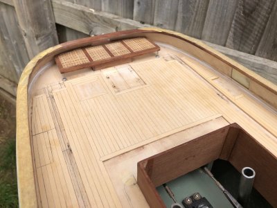
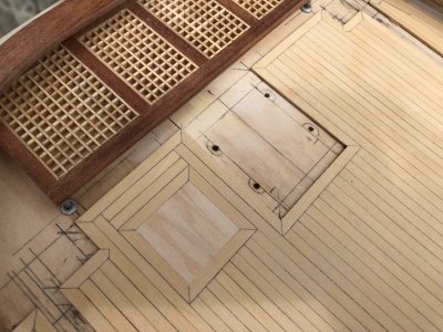
I have made the raised grated deck for the Stern.Thi kit supplied laser cut piece is shown in the pictures, needless to say it didn't pass muster.

My Version is made from Mahogany and uses Caldercraft 2mm gratings ( note scale 1/32). Fabrication was fairly pedestrian, the tricky bit was including the hatch cover for the rudder. The complete assembly clicks into place but is easily removable to get to the tiller arm.The legs were made from 2mm silver steel epoxied into holes in the frame and the feet are kit supplied castings, again firmly secured with epoxy.
IMG_2688.jpgIMG_2689.jpgIMG_2690.jpg

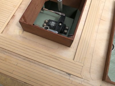
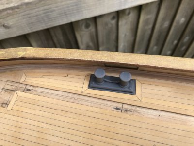
There are only limited sections of this model deck that are planked. Given the size deviation between parts and the plans, I feel it prudent to make up the deck fitting assemblies so I am working to true dimensions.
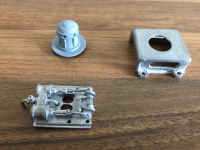
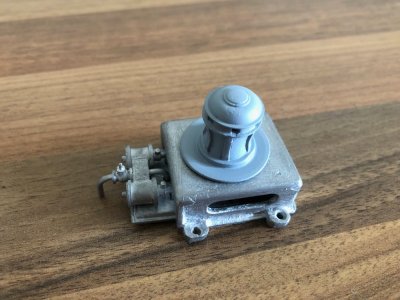
The Steam Capstan that goes infront of the grated deck is one such item. I have built this into sub assemblies and the capstan itself is in etch primer. Considerable time was spent fettling these parts as the moulds must be showing their age. The second photo shows the item plonked together to give you an idea of how this will look.There is a fine cast spoked hand wheel to go on the globe valve of the Steam cylinders. I will fit this just before paint as I feel I am tempting fate fitting it to early. I need to order some small brass threaded rods and nuts to mimic the holding down bolts. These need bonding to the assembly before paint and will also act as dowels when permanently fitting the assembly

IMG_2691.jpgIMG_2692.jpg

All these assemblies can be regarded as little kits in their own right.

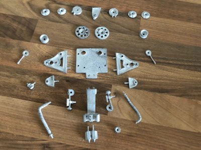
Below shows the cast components that form the anchor winch, minus several tiny items that are staying in the tray till I need them.

IMG_2693.jpg
 
Back
Top