Thanks, merci.Dear Michael (Fish&Chip), Signet,
Here it is, some info in a nutshell...
My CNC machine: what and why?
Hi colleagues, Here, I will share a few words about my CNC machine. Additionally, I will try to provide the results of my small market research that I conducted while searching for a machine. There are the machine specifications: • Working Table: 400mm x 300mm x 135mm • Clearance: 170mm •...shipsofscale.com
-

Win a Free Custom Engraved Brass Coin!!!
As a way to introduce our brass coins to the community, we will raffle off a free coin during the month of August. Follow link ABOVE for instructions for entering.
-

PRE-ORDER SHIPS IN SCALE TODAY!
The beloved Ships in Scale Magazine is back and charting a new course for 2026!
Discover new skills, new techniques, and new inspirations in every issue.
NOTE THAT OUR FIRST ISSUE WILL BE JAN/FEB 2026
You are using an out of date browser. It may not display this or other websites correctly.
You should upgrade or use an alternative browser.
You should upgrade or use an alternative browser.
CNC Machining of Composite Wood at 1:65 Scale
- Thread starter ShipmodelIdeas
- Start date
- Watchers 23
- Joined
- May 1, 2023
- Messages
- 115
- Points
- 113

Hi Paul,A tip...if you post these images 'full size' rather than 'thumbnail' then your fans can take a closer look (or maybe that's what you were trying to avoid).
I finally have full-sized pictures of the finished walls in the Cabin.
You can check them out in my thread here. And yes, the pictures are truly "full size" now.


Santa Maria 1:65 based on Amati kit
Hello everyone, I wanted to share my progress on the Santa Maria 1:65 ship model that I've been building for a few months now. Initially, I started with an Amati kit, thinking it would be an "easytobuild" straightforward project lasting only a couple of months. However, after obtaining books by...
shipsofscale.com
- Joined
- May 1, 2023
- Messages
- 115
- Points
- 113

Today I tried a new endmill on sheet brass.
The goal was to mill out a trial element of the fence. As a fixture, I used a traditional "woodworking" method - two layers of sticky tape with CA glue in between. With sheet metal and on such a small scale, it shouldn't have worked at all. However, the endmill cut through almost everything. And the detail remained in place almost the entire time. Only at the very end did the part begin to come off the adhesive tape, and I stopped the program.
The results can be seen in the photos. The brass thickness is 0.5 mm, and the width of the fence's spoke is 0.75 mm.
Of course, when I make the actual part, I will glue it with CA to an aluminum plate (and the plate will already be somehow fixed on a table).
This method even works with very thick metal.
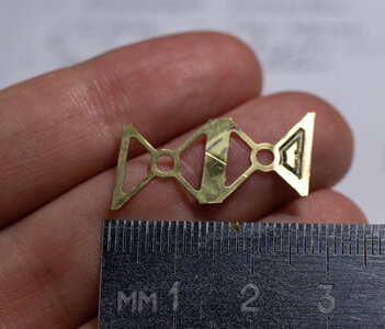
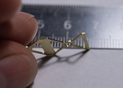


Super quality result - BravoToday I tried a new endmill on sheet brass.
The goal was to mill out a trial element of the fence. As a fixture, I used a traditional "woodworking" method - two layers of sticky tape with CA glue in between. With sheet metal and on such a small scale, it shouldn't have worked at all. However, the endmill cut through almost everything. And the detail remained in place almost the entire time. Only at the very end did the part begin to come off the adhesive tape, and I stopped the program.
The results can be seen in the photos. The brass thickness is 0.5 mm, and the width of the fence's spoke is 0.75 mm.
Of course, when I make the actual part, I will glue it with CA to an aluminum plate (and the plate will already be somehow fixed on a table).
This method even works with very thick metal.
View attachment 381558
View attachment 381559
- Joined
- May 1, 2023
- Messages
- 115
- Points
- 113

Finally, I have returned to composite (layered) wood CNC machining!
I have machined two side panels for my Santa Maria admiral's cabin.
After my first experiment, which was only partially successful, I made certain adjustments to the technology.
1) After several attempts, I realized that the accurate application of glue makes the material rather rigid, eliminating the necessity for a 3-layer sandwich. Two layers would work fine, and I even tried with just one layer!
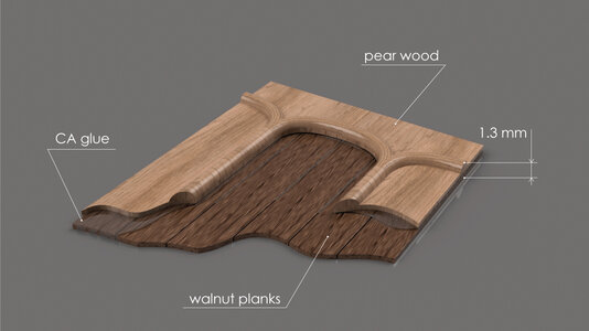
Since these side panels will be applied on top of the final planking, I wanted the panel's thickness to be minimal. Additionally, I aimed to create an illusion that the arcs are empty, revealing the "original" cabin wall planks. To achieve this effect, I had to make precise cuts within the arcs, ensuring that the layer of walnut planks would be visible but not completely cut through.
Therefore, I have developed the following concept:
2. It became evident that the layers had to be completely flat and parallel to each other and to the surface of the wasteboard. Therefore, I spent more time flattening the surfaces. In fact, I flattened all of them
Here is the process:
1) I glued pearwood planks together. Unfortunately, I do not have a belt saw, so I am limited to the maximum width of planks I can make with my Byrnes saw - 20-21 mm (about 0.8 in) wide. Therefore, to have a wider board, I am forced to glue several planks together."
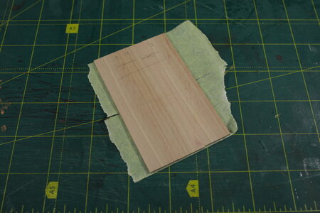
2) Then I flattened both sides of this board with CNC.
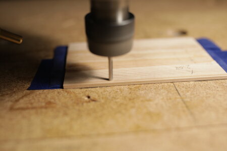
3) Then I added a layer of walnut planks. Additionally, since the two side panels are mirror symmetrical, I had to keep this in mind and maintain the respective angles of the plank layout on each half of the stock... And also flattened that layer with the CNC.
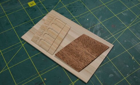
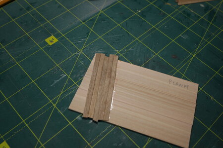
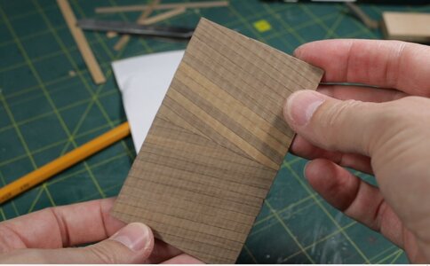
4) Of course, before undertaking all that, I designed the shape of a side panel in Fusion 360.
I aimed for a balance between simplicity and complexity. So, after some consideration, I arrived at this final design:
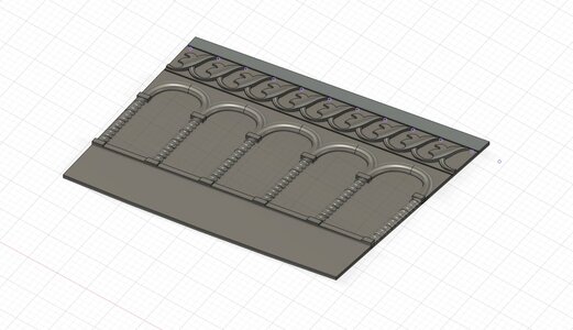
5) Now, onto the most intriguing part - the machining process. If all calculations have been done correctly, I should achieve the desired result. However, if any mistakes were made, half a day's worth of stock preparation will go to waste! With bated breath, I pressed the start button of the program, hoping for the best outcome.
And luck smiled upon me this time :
:
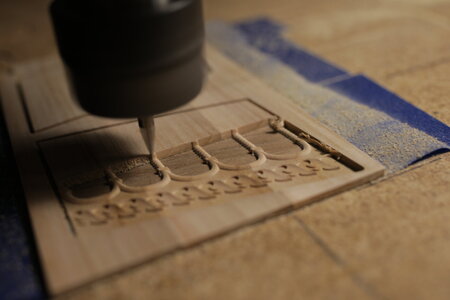
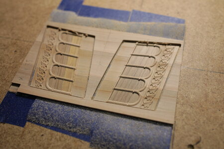
And here is the result. The final maximum thickness of the detail is 1.29 mm (about 0.051 in)!
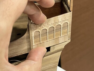
I have machined two side panels for my Santa Maria admiral's cabin.
After my first experiment, which was only partially successful, I made certain adjustments to the technology.
1) After several attempts, I realized that the accurate application of glue makes the material rather rigid, eliminating the necessity for a 3-layer sandwich. Two layers would work fine, and I even tried with just one layer!
Since these side panels will be applied on top of the final planking, I wanted the panel's thickness to be minimal. Additionally, I aimed to create an illusion that the arcs are empty, revealing the "original" cabin wall planks. To achieve this effect, I had to make precise cuts within the arcs, ensuring that the layer of walnut planks would be visible but not completely cut through.
Therefore, I have developed the following concept:

2. It became evident that the layers had to be completely flat and parallel to each other and to the surface of the wasteboard. Therefore, I spent more time flattening the surfaces. In fact, I flattened all of them
Here is the process:
1) I glued pearwood planks together. Unfortunately, I do not have a belt saw, so I am limited to the maximum width of planks I can make with my Byrnes saw - 20-21 mm (about 0.8 in) wide. Therefore, to have a wider board, I am forced to glue several planks together."

2) Then I flattened both sides of this board with CNC.

3) Then I added a layer of walnut planks. Additionally, since the two side panels are mirror symmetrical, I had to keep this in mind and maintain the respective angles of the plank layout on each half of the stock... And also flattened that layer with the CNC.


4) Of course, before undertaking all that, I designed the shape of a side panel in Fusion 360.
I aimed for a balance between simplicity and complexity. So, after some consideration, I arrived at this final design:

5) Now, onto the most intriguing part - the machining process. If all calculations have been done correctly, I should achieve the desired result. However, if any mistakes were made, half a day's worth of stock preparation will go to waste! With bated breath, I pressed the start button of the program, hoping for the best outcome.

And luck smiled upon me this time


And here is the result. The final maximum thickness of the detail is 1.29 mm (about 0.051 in)!

Last edited:
The result is just wonderful - it is amazing 


- Joined
- May 1, 2023
- Messages
- 115
- Points
- 113

Surprisingly I like it too, and maybe will not even bother with improving itThe result is just wonderful - it is amazing


AMAZING!
- Joined
- May 1, 2023
- Messages
- 115
- Points
- 113

Thank youAMAZING!
- Joined
- May 1, 2023
- Messages
- 115
- Points
- 113

thank you!wonderful work, it is looks amazing

- Joined
- May 1, 2023
- Messages
- 115
- Points
- 113

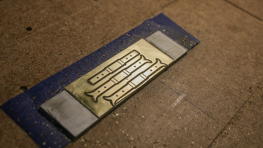
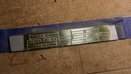
Today I CNC-made parts that are usually made by laser or photo-etched. Compared to photo etching, the details are more accurate. Of course, a laser would be better. But there would certainly be a lot of smoke 
Now, the question always arises - how best to secure the part. In this case, the vise and clamps are not very suitable - the part is too thin.
That's why I use the traditional method. I glue the brass plate (from which I will cut out the details) to the waste aluminum plate (in this case, 2 mm thick). I use cyanoacrylate. And this assembly is then glued to the waste table. I use duct tape and cyanoacrylate, but double-sided tape will work too.
In general, if you are not too tight-fisted and don't place the parts too tightly on the plate, the part does not come off during processing.


What type of mills are you using to cut the brass? In particular I mean are you using multiple tools. One for small details and another for cutting the shape out? Also was wondering what the thickness of the brass is.
BTW, Thanks for posting some really great ideas here.
BTW, Thanks for posting some really great ideas here.
- Joined
- May 1, 2023
- Messages
- 115
- Points
- 113

What type of mills are you using to cut the brass? In particular I mean are you using multiple tools. One for small details and another for cutting the shape out? Also was wondering what the thickness of the brass is.
BTW, Thanks for posting some really great ideas here.
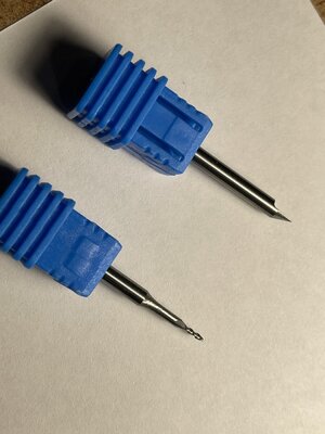
Brass is 0.4 mm thick.
For this part I used 2 tools - to make indentations I used 60 degr engraving mill, for holes and counter cuts - 1mm 2 flutes flat endmill. Here they are:
Hello Max,
Have you started a business making and selling aftermarket stuff for the Amati kit?
I am considering building the Amati Santa Maria, and would be interested.
I found your YouTube videos and will be studying them. I like the idea of lights.
Josef
Have you started a business making and selling aftermarket stuff for the Amati kit?
I am considering building the Amati Santa Maria, and would be interested.
I found your YouTube videos and will be studying them. I like the idea of lights.
Josef
Today I tried a new endmill on sheet brass.
The goal was to mill out a trial element of the fence. As a fixture, I used a traditional "woodworking" method - two layers of sticky tape with CA glue in between. With sheet metal and on such a small scale, it shouldn't have worked at all. However, the endmill cut through almost everything. And the detail remained in place almost the entire time. Only at the very end did the part begin to come off the adhesive tape, and I stopped the program.
The results can be seen in the photos. The brass thickness is 0.5 mm, and the width of the fence's spoke is 0.75 mm.
Of course, when I make the actual part, I will glue it with CA to an aluminum plate (and the plate will already be somehow fixed on a table).
This method even works with very thick metal.
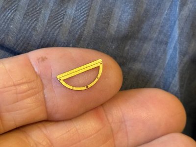
Another approach is to use a CNC fiber laser. This is a top for HMCSS Victoria which is being made for a friend. It is 0.25mm thick, 16mm long, and the 0.5mm holes are centered in the semi round which is 1mm wide. The 30w laser took 90 seconds to make 4 of these. (and no smoke!) The fold line and 2 of the holes were cut at half power. Previous attempts using CNC milling and chemical etching were unsuccessful due to the holes breaching the edge of the round section.
Last edited:
Another approach is to use a CNC fiber laser. This is a top for HMCSS Victoria which is being made for a friend. It is 0.25mm thick, 16mm long, and the 0.5mm holes are centered in the semi round which is 1mm wide. The 30w laser took 90 seconds to make 4 of these. (and no smoke!) The fold line and 2 of the holes were cut at half power. Previous attempts using CNC milling and chemical etching were unsuccessful due to the holes breaching the edge of the round section.
View attachment 564643
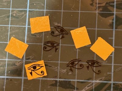
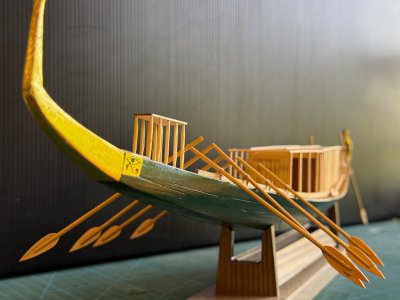
25 Dec 2025. And if I may bang my CNC laser drum again, some parts made on the 30w fibre laser for the Khufu pyramid "solar" ship.
These are brass cutouts for the sides of the hull near the prow. They are 11mmx9mm x 0.1mm thick. The eye is painted with black acrylic ready to attach to gold foil covered brass backplates.
Last edited:


