Danish Bomb Vessel 1771, "Den Gloende", POB, 1:48

I didn't take a lot of photos as I did this, it was all pretty straight forward. I finished the upper planking and then cut out the Gun Ports and sweep ports over the weekend.

I added framing up to the bow for the railing, before I sanded the upper plank down to rail level. I made the odd shaped framing from left over walnut from laser cut sheet waste from kits. In the photo below you can see the slight indentation by the upper portion of the stem. This matches the opposite side and came out very symmetrical. The upper rail is off of the template by about 1mm in the sharpest curving portion on each side, but the same on each side. I'll get a photo of that.

I drilled a .5mm hole from the back of the sweep ports, then used a square diamond covered file to open them up. This allowed me to adjust the alignment a bit as I worked. The framing on the end sweep ports was a little low, but I just did some extra filing on the top and didn't go all the way to the bottom. I'm very happy with the look.

dg118-XL.jpg


Next thing I would like to do is plank the lower hull. However I'm going to wait a while on that because I ordered a thickness sander from Byrnes model Machines a week or so ago. When I get the planks cut on my table saw they're sill pretty rough. They looked pretty good but in this case required quite a lot of sanding after installation. More consistent planks will save me a bit of manual work. Got to wondering how much thicker I should cut the plank for sanding allowance?

Will probably start working on the sub-decks at this point.
 
Last edited:
Well, while I'm waiting for my thickness sander and working on other projects these parts arrived. I did the Design and drawing in Autocad, and Mike Shanks cut them for me. This is the nicest laser cutting I've ever seen. There are no burn marks as you can (not) see. The window cross bars are 1 1/2" to scale, no way I could have made them from wood with the tools I have. Can't wait to put them on, but I have too or I'd almost certainly end up with something broken. I also just noticed I cropped the photo a little to tight on the right side there is more wood on the right of the parts there.

The trim strip will be contoured and added to the top of the stern plate, The rings go around the round holes. The lower window frames go In the gun port openings near the back of the ship. None of the ships of this class were outfitted with guns on the stern from the information I can Find. There is reference to windows being installed. The arched pieces are rings that go around the mortar mounts and will have a scale for rotating degrees for aiming.

den0033-XL.jpg
 
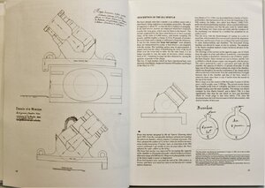
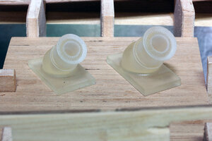
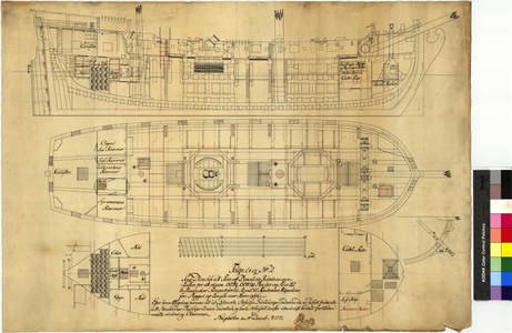
So yesterday I spent about 7 hours creating 3D models of the Mortars for this ship, and then this afternoon I ordered them printed by Shapeways. This is one place where the Danish approach is considerably different from the english approach. Note the mortar is cast as part of the base instead of hinged like on the Granado. I've seen several photos of this type mortar with a wedge system under it to adjust the angle. Based on the ship plan for the Gloende it appears they just used different gunpowder charges to change the range. The plans show a lot of detail but no wedge. I didn't model the portion of the plate that goes down in the front because it will be hidden by the carriage

Here's a rendering of the 150 pound mortar in cast iron, should have them in a couple weeks.

DEN0036-M.jpg


G-4129%20Mortar%20Section%20Feb%201771-L.png
 
Last edited:
Looking very good - very good result.
The french La Salamandre had the same type of mortar with a fixed angle to the base of 45 degrees.
IMG_33261.jpg
The range distance was adjusted with the gun-powder and also the distance of the ship towards the target
The way of working of these vessels are well shown and explained in
and
 
Thanks for the compliment.

I never intended to produce a set of plans for sale or distribution or anything like that. When I'm finished I would be willing to give the computer files that I create away. I just don't want to go into business and become technical support for the errors in the plans and printing them etc. If someone wanted to use them it would be at their own risk.
 
Zoly, I haven't done anything with it since the last time I posted. I have been getting the bug gain though. I Just looked at it this morning and decided it was about time to get back to it. I finished the Black Pearl with the exception of the sails. I should finish the sails and then one machining project before I get back to this probably, but I'm feeling more excited about this project.
 
So I finally got the urge to work on this project again. I actually tried a couple times but kept getting stuck on how to proceed with the planking. I'm not good at planking and don't really like doing it. Kind of goes hand in hand. That being said I do want to move forward on this project and am excited about the rest of the build once it is planked. So I didn't take a lot of photos but starting Friday night I just took a swing at it.

Here's where I finished last night. I made a garboard strake and didn't attach it right away because I had my doubts about the shape being correct. After doing the planking in the photo I decided it would work and attached the garboard strake.


On the aft of the ship I just used full width planks because I thought it looked good. That of course means now I need to adjust plank widths on both ends to not have a bunch of pieced in sections. I decided to plank from the top down so if I do end up piecing in a section it should be on the bottom where it won't show.


And here is a overall view.


I do believe I finally got the planking thing figured out. Not here obviously but in the future. I'll be able to do much better. The last part I was really having issues with was the tapering. I don't really have any good way to hold and taper planks so I ordered some tool steel and will be building a proper plank tapering jig. After thinking about it a bit it occurred to me that I could then 3D print a piece for the center of the tapering jig. Could be a long explanation, I'll just leave it at that. I'll post some photos of the jig when I build it.

The other thing that stopped me was I ran out of planks. So this morning I got out the Byrnes tools and made a bunch of planks. I did about 30 more than I needed to finish the hull and the made about 40 out of cherry so I'll have something to use on the whales and deck.


In the last year I've gotten more information on the correct mortars and guns so those will need to be drawn and either printed or machined so they are the correct Danish versions instead of English versions. So more to come in the near future.
 
Thursday, I received two, 18 inch long 1-inch wide 1/4" thick, tool steel strips I ordered from online metals. I stacked them together and drilled 2 holes for 3mm bolts 200mm apart. On Friday evening I drew up and printed 2 plastic guides. The dimensions were created by measuring the gaps I needed to fill along the hull. I did 2 different inserts because the front and rear taper are different. Here's what they looked like.


The idea is when the strips are placed together the planks will sit on top of the plastic as shown below.


This worked really well. It eliminated the need to measure each individual plank because I just lined it up with the end of the plastic guide inside. I was able to taper a plank about ever 30 seconds with this method. I showed the c-clamp on the end because when you get more than about 5 inches from the vice jaws the grip of the strips is reduced to the point the wood can slip. This would only be needed if you were taping a plank more than 12 inches (300mm) long. I initially was going to add screws with wing nuts on the ends but realized that could be in the way if the taper was more extreme. I could also do a arched taper by printing the center insert with an arch and pressing the plank into it.


So, then I tapered planks and finished planking the hull.


I planked down 4 rows from the post above and it was becoming clear that my garboard strake was way out in left field. I stopped and measured the distance to the keel on all the frames and the were within 4mm's. So I tore the garboard off and continued planking down. This fit well on the stern.


On the bow it was clear that my previous errors had me backed into a corner where the bend needed to keep adding rows was just too extreme to work. I ended up adding 3 scabbed in strips to fill it in. I really knew pretty early on I had this problem but I didn't want to start over. I know how to solve this in the future.


It's far from perfect, but to this point the best single layer planking job I've done. Actually; it's my first attempt at a single layer of planking so that isn't all the high a bar. For the most part I'm happy with it. With a little filler and sanding it'll pass, and the scabbed in section is hidden from the side. I turned up the contrast in the photo below to exaggerate the rough areas.


Along with smoothing out and finishing the planking I'm going to go back and revisit making some 3d files for more accurate cannon and mortars.
 
I printed out my sub deck templates and set them in place to see how close they come to fitting in the ship. I wrote some notes on them in red as to what tweaks I need to make to get them to fit. They were really a pretty decent fit as you can see here.


Well over the last week I had some time to tinker away with this. I sanded the hull and added a little filler. I'm quite happy with the hull at this point, so I spent some time figuring out what I needed to do next. Here is a couple photos of the 90% sanded hull. I should mention for those that might be wondering, that the plans for this ship show the whales being flush with the outer planking on the bottom and very close to flush on the top. There should be a 0.5mm (.02") ledge on the top to scale. I just decided it wasn't worth the effort to try and get that small detail to show up and made it all flush.


Next, I got out all the Byrnes stuff and made a bunch of sawdust. I didn't take any photos because I'm fond of my fingers and figure everyone has seen their tools anyway. Given the amount of sawdust i made it always seems like I don't have much to show for it, but I typically make a lot more stuff than I need for the current project. So I have a fair amount of extra strips in various sized all cut and sanded. What I did take a photo of is the parts for the mortar bed. Here are the basic parts all cut from cherry.


I also cut some walls and framed in the Mortar Pits, as well as planked the insides. Here it is with the pits installed and the centers marked.


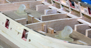
The started gluing and stacking the beams that the mortar sits on. Most of this will be just partially visible after the mortar and framing on the main deck are added. I decided this needed to be constructed before the deck was attached. This is one place where the Danish version differs greatly from what the English were doing at the time. In the section drawing in post 44 you can see that the mortar actually set on top of a bunch of rope that acted as a shock absorber. These parts are meant to depict the outside frame of the pit and the wood structure above it. The mortar actually rotated on top of this portion. I glued sanded and attached the pieces Mike laser cut for me, which will have the scales to adjust the angle.


I then attached those parts to the pits. I'm going to have to figure out what to do for a finish before I get much further along.


I then placed a set of adjusted templates to see how things were fitting. I adjusted the rear mortar pit forward 1.5mm and moved the hatches behind the pit back to fit better.


The next part I think I'll be working on besides creating some files for cutting and printing will be the rear cabin area.
 
Highly interesting post of your work - and very good work :cool:
BTW: In the section drawing in your post 44 we can also see the thickness of planking and wales - very good detail
 
Thanks, Uwek, and everyone for the likes.

During the rather long time I was not working on this model I was able to find a lot more information, mostly due to a ton of help from a retired Danish Naval Officer. One thing he researched for me was the confusion about what weapons were actually on board these ships. I think I mentioned early in this log that the plans listed a couple different possible loadouts for this ship. Klaus was able to confirm that the ships were intended to carry one of two different sets of guns based on the mission the ship was on. Later maintenance reports list all of the vessels in this class as having carried, two mortars one 150 and one 100 pounds, as well as 4-12 pound and 6-4 pound howitzers (haubitz). Klaus was able to find a plan for a howitzer at the time. here it is.

1599773901_5755_FT36791_f364_page_1_howitzer-L.jpg


This plan is for an 8 pounder. I adjusted the size based on the size of the balls. I went through several plans that gave dimensions of different sized Danish canon and found that they were consistently sized based on the size of an Iron canon ball. What I mean is the diameter of a 4 pound canon ball is very close to 80% the size of a 8 pound canon ball. I you take the length of the gun, thickness of the barrel, width etc. and do the same calculation you keep getting the same percentage of size difference. So while I only have one dimension to verify this for a howitzer, (I do have the length of both the 4 pound and 8 pound howitzer and it also calculates to the 80% number), I feel like it's probably really close.

So based on the plan above, and some copywrited photos I can't post, I drew a 3d model of the howitzers barrels. Here's a rendering of the 4 and 12 pounder side by side. The round pommel on the end was based on the photo of a real Danish howitzer from the time.

Haubitzer%20v2-L.jpg


These howitzers make sense when you look at the confined space on the deck of the ship, because they are very short. The mortars take up so much space there is only about 5.5 feet (1.67 meters) of space for the 8 gun ports that are adjacent to the mortar pits. A standard 4 pound Danish gun which the barrel is 6 foot 4 inches (1.9 Meters) long, would be tough to handle in such a small space. The 4 pound howitzer is only 2 feet (0.6 Meter) long including the pommel on the end. The overall length of the 12 pounder is about 3 feet (1 Meter). The carriage doesn't add much length. I don't have a actual plan for the carriage just copywrited photos, so I'll show that once I get them designed. Here's the deck plan.

1652282592759.png

The purpose of these small guns as listed in one of the diary entries I read was to repel boarders in small boats.
 
Last edited:
So I have been working on the ship the last few weeks but mostly via the computer. First I drew up the Falconets from the actual plan. Then I drew and 3d modeled the Mortars from the plans. I think I mentioned earlier that the first mortars I did were from the ship plan and apparently stylized by the draftsman. Now that I have the actual plans, so here is the new 3d model of the 100 and 150 pound mortars. I did not draw the toe on the front because it would be hidden on this model and just make it harder to assemble.


I also spent quite a bit of time drawing parts for laser cutting. Mike Shanks did the laser cutting and I'm eagerly awaiting those parts, Ill post a photo of them when they get here. Here's a teaser pdf.


He also Printed the mortars and other guns for me. I mentioned in the last post that the Howitzers are really small. I expect people will be telling me that I messed up the scale on a pretty regular basis, but I checked it repeatedly. Here is a photo of the guns Mike Printed for me. From left to right are 8 one pound Falconets which are longer than the 12 Pound Howitzers. 4 - 12 Pound Howitzers center, and 8 - 4 Pound Howitzers on the right. The carriages for the Howitzers are in the laser cut parts above.


In this photo you can see the 4 pound howitzers at 1 to 48 are about 12mm long.


I did also have a little time to break out the scroll saw and cut the subdeck for the Cabin and Main Deck. Don't probably need to do the cabin as it will be really hard to see anything being as there are just 4 windows where the four gunports are in the cabin. Every reference I have indicated the cabin gun ports were never used as gun ports. These aren't glued in I still need to do some details and finishing where there will be holes in the deck along with the mortar pits.


I've also been debating on what to use as the planking for the deck. I've pretty much come to the conclusion I should use the Alaskan cedar in a narrower width, which means I need to cut and sand planks before I can move forward on the deck planking, So that will likely be my next project. Though you never know which direction I might head.
It is obvious that the time and effort you have invested are achieving very impressive results, waiting to see how the other details you have designed come out. :)
 
So finally getting around to doing a little update from last weekend. I received my laser cut parts from Mike on Friday. Here they are.


This gave me a lot of options of things to work on and I just kind of went off on a tangent. First, I tried assembling one of the Tiny 4 pound Howitzers, just out of curiosity to see if it would even work. Here is a photo of the carriage and other parts. This is going to work well. I did get the barrels and mortar painted but don't have a photo with the black barrel.


My next mission was gluing the rudder parts together and sanding them. The tiller isn't attached and I left excess wood so I could shape it later. I love the look, I left the char where the pintles go because I thought it looked good. The black in the seams is just from the laser char.


And lastly I built the Mortar carriages. I spent quite a bit of time on these. After gluing the pieces side by side I sanded the ends to match the rounded shape of the area in the mortar pits. I also added the eye bolts and rings that would have been used to move the mortar from ship to ship. I messed around with different finishes on some scrap lumber and once again went back to my old standard Amber Shellac for the finish. I'll use this finish on the rest of the exposed wood on the ship as well. The Mortars are painted with Tamiya Acrylic Nato Black. Use this paint a lot on my train stuff.


My next project I'll probably get into is playing with soldering some brass. It's something I've never had a lot of luck with because of heat control issues. I bought a resistance soldering setup and am hopeful that will help be get it right finally. The next real logical step is to work on the stern so that is the area of the ship I'll concentrate on, most likely by trying to make the rudder hinges from brass.
 
Back
Top