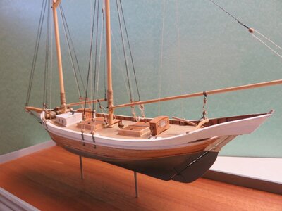
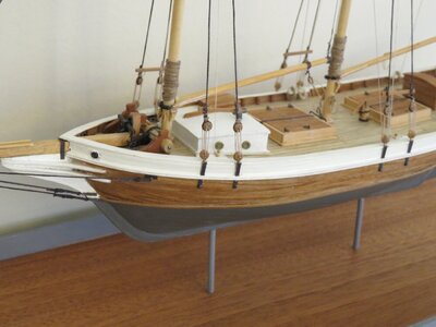
Dove - A pinkie Schooner in 1/48 Scale [COMPLETED BUILD]

Joined
Mar 9, 2020
Messages
310
Points
238

Location
Washington Crossing, PA
In his book “The American Fishing Schooners” (AFS) Howard Chapelle devotes a chapter to the development of the double ended pinkie as a fishing vessel. He also writes about this design as a pleasure craft in “American Sailing Craft”. Chapelle obviously thought highly of the sea worthiness of pinkies since he built one for his personal boat. AFS contains particularly well detailed plans of the pinkie Dove which had an length between perpendiculars of 42'11”. As a result, many models have been made using these plans. In a build log on the Model Ship World site (https://modelshipworld.com/topic/27242-pinky-schooner-dove-by-jlefever-148/), J.L. Le Fever describes building the Dove by both the solid hull and plank on frame techniques and also gives a detailed analysis of the hull design. In this log I will present my version of the Dove as a plank on bulkhead model in 1/48 scale.
For those readers who are interested in building small, this will be the fifth model with a hull length of about 12” that I've posted about on this web site since retiring from building large models of sailing ships.

Plans

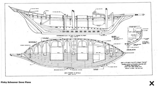
Figures 1 and 2 shown the plans for the Dove in “American Fishing Schooners”. There is also a rigging plan that I will display later on. These plans were enlarged to 1/48 scale on a copier.
Figure 1
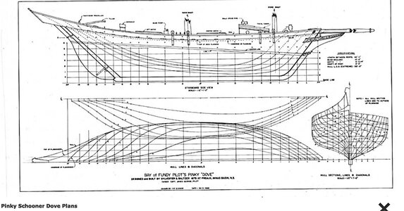
dove lines.jpeg

Figure 2
Dove general arrangements.jpeg


Skeleton Construction
From the body plan, the hull cross sections at 13 station lines were selected for making the bulkheads. Paper templates from the plans were glued onto 3/16” plywood to form the keel piece and bulkheads except for the foremost and two aft most bulkheads which were 1/8” plywood. Per the plans the keel would be about 1/8” in scale but I used 3/16” for greater rigidity. I will later sand the exposed edges of the keel piece to 1/8”.
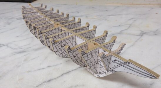
Figure 3 shows the keel piece and bulkheads and Figure 4 indicates their appearance after dry fitting to check alignment, etc. Note the pockets that have been added to the keel piece to guide positioning of the masts later on.

Figure 3
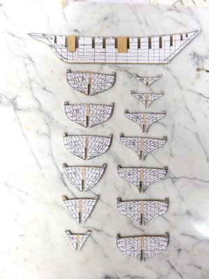
F3 bulkheads.jpeg
Figure 4
F4 dry fit.jpeg

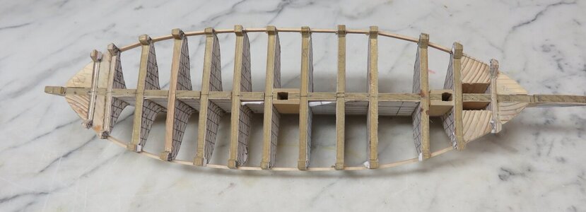
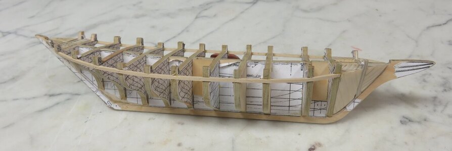
Figures 5 and 6 show the hull after the bulkheads have been glued in and faired and filler pieces added at the bow and stern. A 1/16” x 3/32” stringer was set into notches in the bulkheads to support the edges of the plywood sub deck.

Figure 5
F5 assembly.jpeg

Figure 6
F6 assembly top view.jpeg

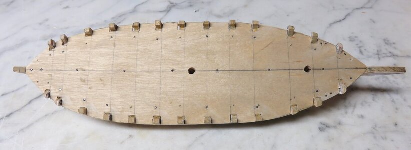
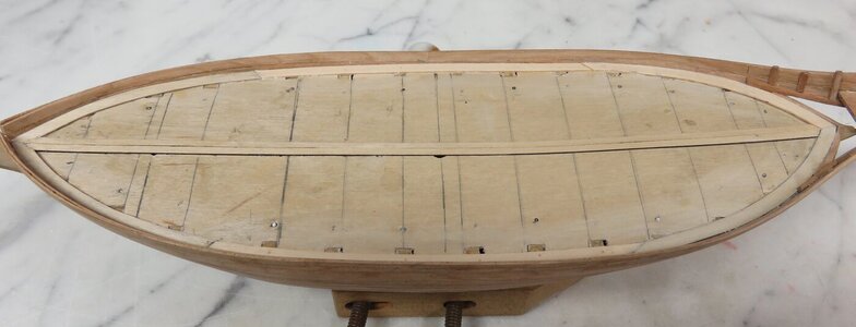
A paper deck pattern was made from the plans, glued to heavy paper, and fitted around the bulkhead extensions (Figure 7). This was then used as a template to cut a sub-deck from 1/32” plywood which was glued and nailed to the surface of the bulkheads (Figures 8 and 9).
Figure 7F7 deck template.jpeg
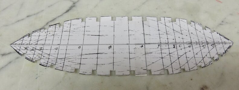
Figure 8
F8 subdeck.jpeg
Figure 9
F9 frameing.jpeg

This completes construction of the skeleton and next up is planking.
 
Very good start - the model and the log
I will follow with big interest
 
Hull Planking


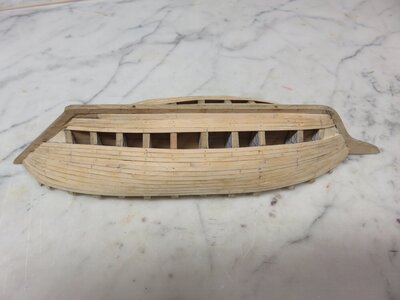
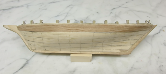
The hull will receive a first layer of 1/32” bass wood planking and a second layer of 1/32” cherry. According to Chapelle's plans, 20 planks were used to cover the hull from the deck to the keel. The perimeter of the dead flat bulkhead measured 60 mm indicating that 20, 3 mm planks would be required.

Various methods are available for planking a model, and the one I like best is to divide the hull into a number of zones with battens placed to give a fair run. For this model, 5 zones with four planks each seemed about right. Marks were made on the dead flat bulkhead 12 mm apart and a batten was tacked at the first mark below the deck. The batten ends at the bow and stern were then adjusted to give a smooth curve by eye along the bulkheads and the position where the batten crossed each bulkhead was marked. The batten was then moved 12 mm lower and the process was repeated four more times. The perimeter between zone boundaries was measured at each bulkhead and then divided by 4 to get the plank width at that position. Planks were then tapered accordingly.

Starting at the deck, the first three zones were planked and then the 5th zone was planked from the keel upward. The model at this point is shown in below:
Figure 10
Fig 10 MG_2179.jpeg

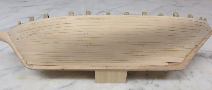
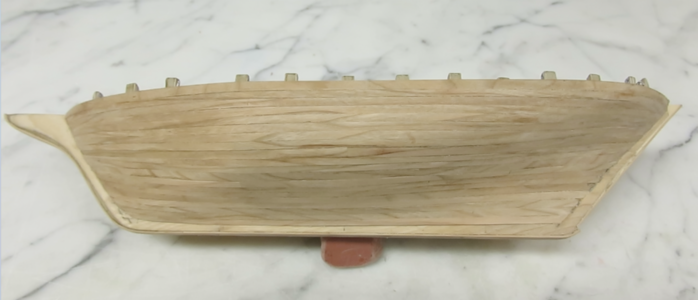
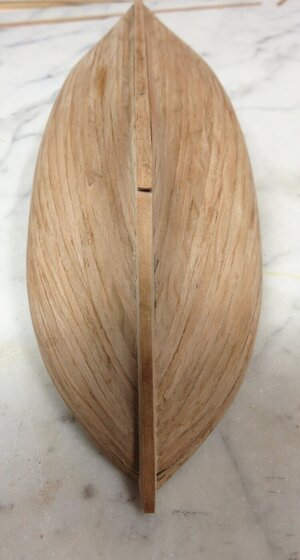
The final gap (zone 4) was then filled in (Figure 11) and the hull sanded fair. No stealers were required.
Fig. 11
Fig 11 IMG_2181.jpeg

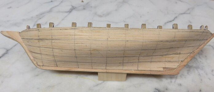
As can be seen in the lines plan in Figure 1 the bulwark planking extends beyond the stern. Not wanting to risk damaging this area while working on the model, I decided to complete the two layers of planking on the hull before adding the bulwark planks. For the cherry planks, the same procedure described earlier was used to lay out 5 planking zones. The hull with the zones and station lines marked in pencil is show in Figure 12:
Fig 12Fig 12 IMG_2182.jpeg
 
Second Planking

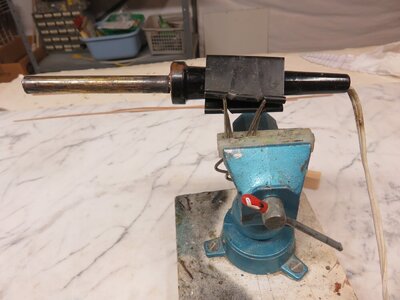
There has been a lot of discussion in the Help Forum about plank bending, so before writing about the second planking I will chime in with my technique. Shown below is my plank bender which consists of a piece of 1/2” copper tubing slipped over the barrel of a soldering iron to dissipate the heat.
Fig 13 plnk bender.jpeg

The plank is dipped into water then bent to shape around the tubing. This gives instant results and works very well for planking thicknesses of 1/32” - 1/16” (1 – 2mm).
As with the first layer of bass planking, 3mm wide cherry planks 1/32” thick were added to fill in the planking bands starting at the deck line.
Fig 14 2nd plnk start.png

When possible, I prefer to use a single strip of planking from stem to stern since planking butts can always be cut in later if desired. However for a double ender this adds a bit of bit of difficulty because the plank length has to be cut accurately to fit snugly in the stem and stern rabbets at the upper part of the hull.

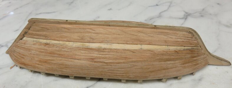
Planking continued downward to about mid-hull, then it was started from the keel upward until only the final planking band remained.
Fig 15 2nd plnk end.jpeg

After this section was filled in the hull was sanded fair.
Fig 16 2nd plnking.png
Fif 17 2nd plnking.jpeg

With the planking completed, a strip of 1/32” cherry was glued around the edges of the plywood keel piece for better appearance. Lacking sharp bends, this was an easy hull to plank, and no stealers were needed as mentioned earlier.

Bulwark Planking

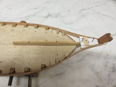
As shown in Figures 1 and 2, the bulwark planks extend past the stem in a complex curve where they are joined to a stool and small transom called a tombstone. How to hold all of the pieces together in the required shape for gluing required considerable thought on my part. The bulwarks will be double planked with 1/32” cherry. I first added an initial 1/32” bulwark plank about one half the needed width at the transom end which was bent to the approximate shape where it extended beyond the stem (inner bulwark plank). Then a wood beam was sized so that when nailed to the deck aft, it reached over the stem to the position of the transom with the end cut to the transom angle. The height was set to the height of the stool. The stool was then attached to this beam with some planking nails and the transom was put in in place with a nail into the end of the beam. The first bulwark plank was then glued to the stool and transom. Next, an outer bulwark plank was glued over the first inner plank, overlapping the upper edge to provide gluing surface for a second inner plank. The stern a this point is shown below:
Fig 18 stern jig.jpeg

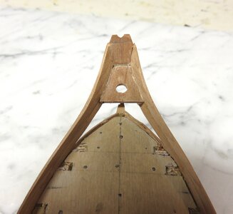
Continuing in this fashion, inner and outer planks were shaped and added until the desired structure resulted. When the planking and gluing were completed the wood beam that served as a jig was removed. Fig. 19 shows the final appearance of the stem :
Fig 19 stern plnk.jpeg

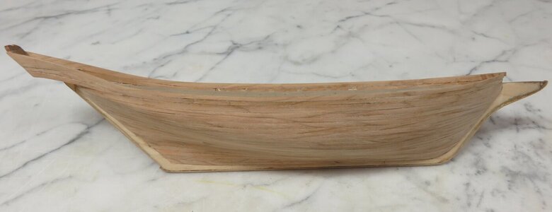
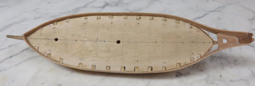
The completed hull planking is illustrated in Figs. 20 and 21:
Fig 20 bulwark plnk.jpeg
Fig 21 plnk topview.jpeg

The next work is the sequence will be to plank the deck and add the railings.
 
Deck Planking
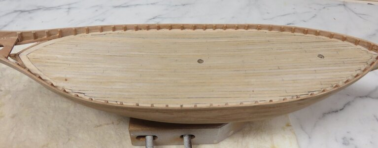
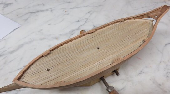
Deck planking was cut from a sheet of 1/32” birch plywood. First a margin plank was installed on the sub-deck along the bulwarks, and then two planks were laid on either side of the centerline :
Fig. 22
Fig 22 margin plank.jpeg

Planks were 3/32” wide as estimated from the plans.
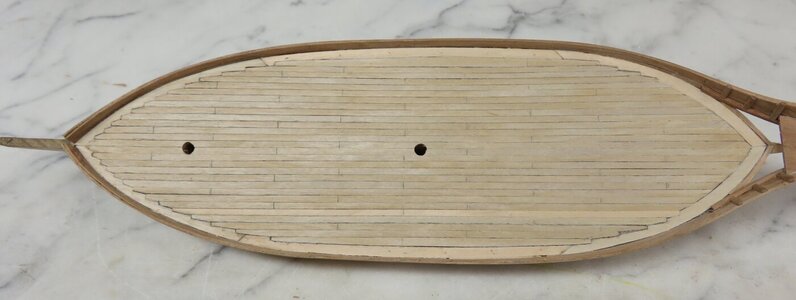
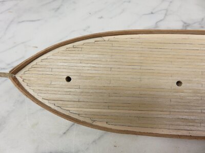
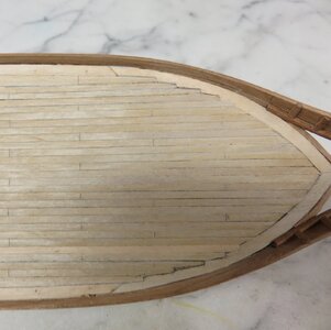
Planks were glued in single strips extending from bow to stern. One edge of each strip was blackened with a fabric maker (I have found the ink in a fabric marker does not run after stain is applied.). Plank ends were nibbed at the bow and later on at the stern as the angle of the ends became more acute. Figs. 23 to 25 show the completed deck and details at the bow and stern.
Fig. 23
Fig 23 ompleted planking.jpeg
Fig.24
Fig 24 nibbing at bow.jpeg
Fig. 25
Fig 25 nibbing at stern.jpeg

Hull Completion
The plans show the second futtocks of the frames extending up to the shear line to serve as stanchions for supporting the bulwarks. Of course in a plank on bulkhead model there are no frames. On this model, the bulwarks were double planked with offset plank edges to provide strength without being otherwise supported. Thus adding stanchions would be for the sake of appearances only. The stanchions were made from 1/16” square cherry and glued onto the bulwarks at 3/8” intervals.
Fig. 26
Fig 26 stanchions.jpeg

Cap rail shape was determined by tracing the top edge of the bulwarks onto a piece of paper which was then used as a template for sawing the rails from 1/32” cherry sheet :
Fig. 27
Fig 27 cap rails.jpeg

They were sawn slightly oversize and sanded to the final width after gluing on to the top edge of the bulwarks and stanchions. After the rails were installed, pinrails were attached.
Fig. 28
Fig 28 rails installed .jpeg

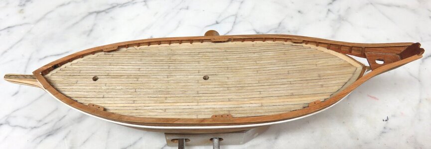
Next, plank butts were scribed in the deck planking assuming a 16' plank length at full scale and a 4 plank repeat pattern. These butts can be seen in the above figure. The appearance of the deck after a coat of Minwax Natural Stain has been applied. Is shown below:
Fig. 29
Fig 29 stained deck.jpeg


The butts now stand out more clearly and I was pleased with the look of the blackened plank edges to simulate caulking.
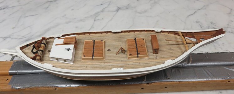
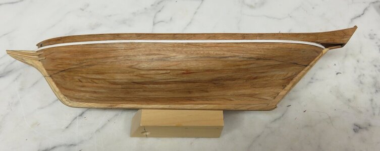
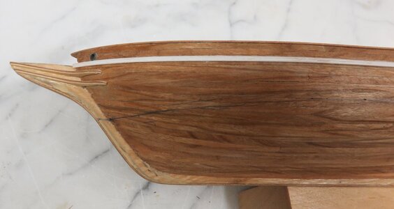
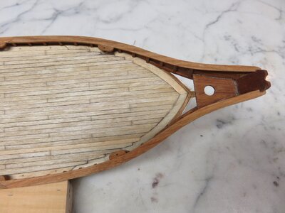
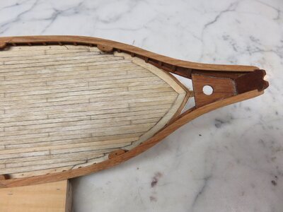
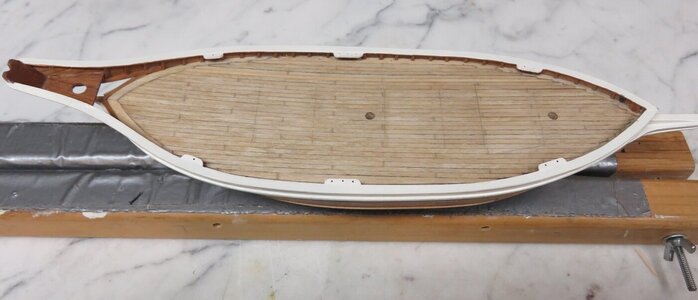
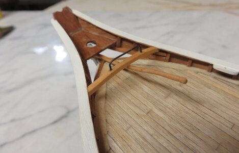
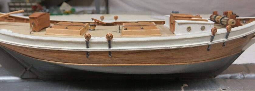
To complete the carpentry on the hull, a piece of molding, painted ivory, was added at the plankshear, hawse pipes (1/8" brass tubing) inserted at the bow, and two head knees added to the stem. Fig. 30 and 31 shows these details after the application of a coat of Minwax Natural Stain to the hull. Stern details are in Fig. 32.
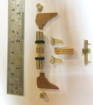
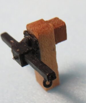
Fig. 30
Fig 30 stained hull w molding.jpeg
Fig. 31


Fig 31 head rail detail.jpeg
Fig. 32Fig 32 stern detail.jpeg

A pencil line denoting the water line can be seen in Fig.30.
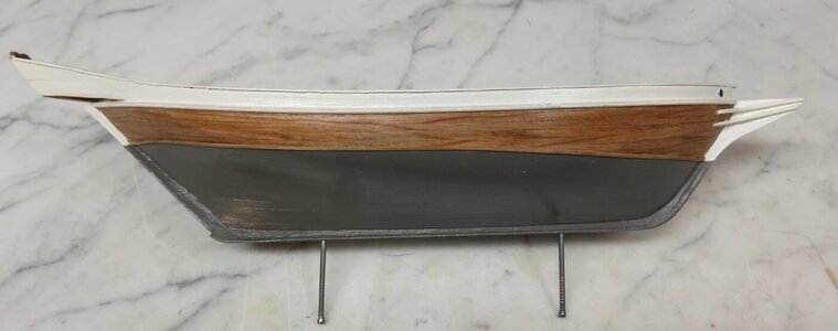
Rather than leave the hull with the natural cherry color, I decided to paint the bulwarks and cap rail ivory and the underwater part of the hull dark grey to match the other small schooners I have recently built and posted about. The hull planking between the bulwarks and water line will be left natural.

Fig 32 stern detail.jpeg
 
Hull Painting
The hull and cap rails were painted with the inexpensive craft paint available in U.S. craft stores such as Michaels and Hobby Lobby. The pigment in these paints is not as finely ground as in model paints so the finish is not as smooth, but the cost is much less and the range of colors available much wider. After painting the hull, the hull and deck, except in the areas where the hatches and cabin will be erected, were given a coat of satin polyurethane varnish with the result in the below figures.
Fig 33 painted hull.jpeg
Fig 34 deck painted.jpeg

Rudder
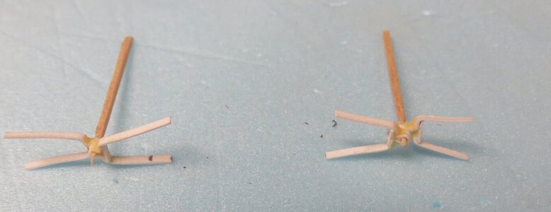
The plans indicated the rudder was made in two sections. Using a paper template, two pieces of 1/8” cherry were sawn to shape, glued together, and given a final sanding to round the leading edge and taper the trailing edge. In past models of large vessels, I have made gudgeons and pintles from brass strips bent into a U-shape with a section of 1/16” tubing soldered to the bottom of the U to receive a pin. They were nailed to the rudder and hull and served to support the rudder. In the small boats I am making now I have switched to paper from 3x5 cards for these parts because I think they are more in scale.
I cut a paper strip and wrap it around a #74 pin to form a loop which is then glued at the throat to keep it closed. It is then bent to shape around the rudder, and the outside of the strip is given a thin coat of CN glue to stiffen it. Finally the gudgeon and pintle are connected together by gluing a wood pin into the loops as shown in the figure:
Fig 35 hinges.jpeg

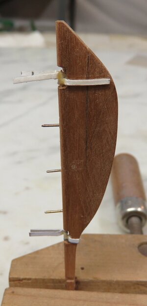
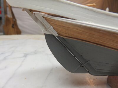
The rudder is attached to the hull by inserting three small pins in the leading edge and and drilling matching holes in the stem. Fig. 36 gives the appearance of the rudder after the pintles have been glued on and the pins inserted, and Fig. 37 shows the rudder, after painting, attached to the stem:
Fig. 36
Fig 36 Rudder construc.jpeg
Fig. 37
Fig 37 mounted rudder.jpeg

To finish work in this area, a tiller was made by sanding a taper into a length of dowel and then bending it to the desired shape with heat. Prior to inserting the tiller in the rudder, a horse mounted on a beam was glued to the bulwarks. The completed assembly is shown below:
Fig 38 tiller and horse.jpeg
 
Deck Funiture

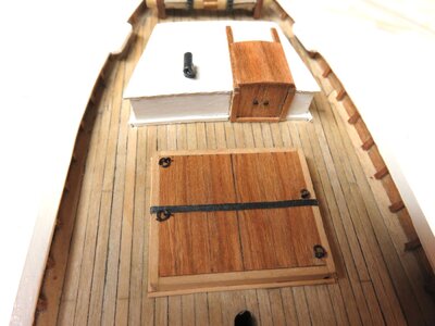
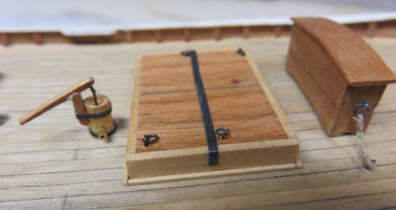
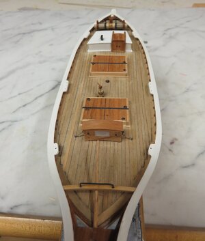
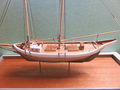
Fig. 39 shows the deck with all of the furniture installed consisting of a windlass, deck cabin, hatches, pump, and binnacle, each of which are described below.
Fig 39 deck furn.jpeg

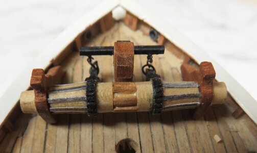
1. Windlass
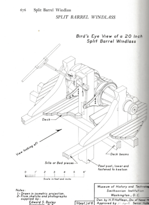
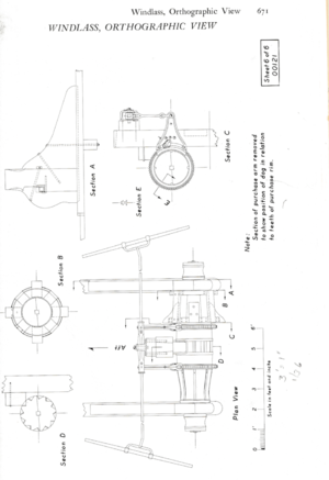
Plans for the Dove just show the general outlines of the windlass and lack detail. However, in a very long Appendix section of AFS discussing various features of fishing schooners, Chapelle devotes about 16 pages to design of windlasses. The one most appropriate for Dove is the pump brake windlass depicted in the two figures below :
Fig 40 windlass1.png
Fig 41 windlass 2.png

The drawing shows the two halves of the windlass barrel differ, but I made them the same for ease of construction.
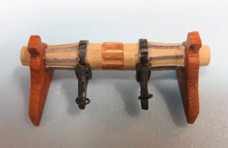
The barrel was made from several pieces of dowel of different diameters. The center section was 3/16” diameter with 1/32” gear teeth glued on bringing the outside diameter to 1/4”. Glued to either end was 5/16” diameter dowel with gear teeth filed in along the edge. Finally, two pieces of 1/4” dowel were tapered to shape and attached to the gear wheels. Blackened paper was glued on to simulate iron whelps. The rocker arm assembly was made by soldering together various pieces of brass. All of the parts that went into the windlass assembly are shown in Fig 42:
Fig 42 windlass parts.jpeg

The next three figures show the windlass and rocker arm before and after installation on deck.
Fig 43 rocker arm.jpeg
Fig 44 windlass.jpeg
Fig 45 windlass on deck.jpeg

2. Cabin
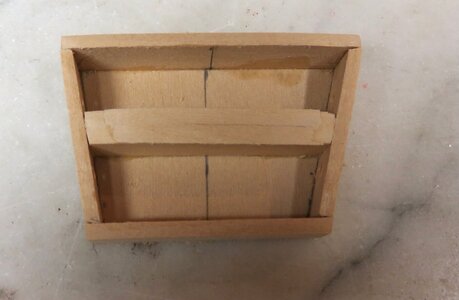
A base for the cabin framework was cut to shape and then basswood sides were glued on as well as a central member to support the roof planks:
Fig 46 cabin framing.jpeg

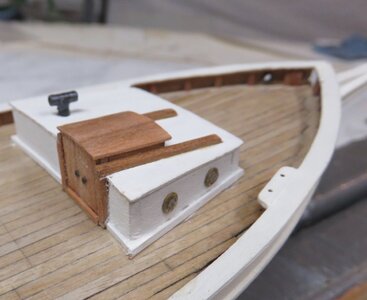
After adding the roof planks, a companion way was made from cherry and a galley stack from two pieces of 1/8” brass tubing soldered together. Grommets were installed in the holes drilled into the cabin sides to simulate portholes. The completed cabin was then glued to the deck:
Fig 47 cabin.jpeg

3. Hatches
Basswood hatch framing was glued around as base, as with the cabin construction, hatch covers added, and then the completed assembly glued to the deck. The hatch cover was based on the design provided by Chapelle which shows a iron strap holding down the cover:
Fig 48 hatches.jpeg

4. Pump
The pump barrel was a piece of 3/16” dowel with added handle and brass discharge pipe:
Fig 49 pump.jpeg

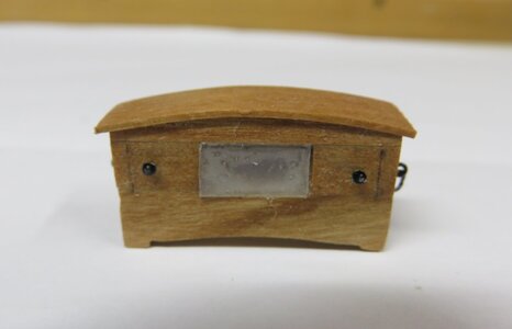
5. Binnacle
The plans only show a edge view of the binnacle which indicated the width and height. However the length could be estimated from other pinkie plans in AFS. To construct the binnacle, a basswood core was cut to the desired dimensions and then 1/32” cherry wood was glued to it. The completed binnacle before and after installation on deck is shown below:
Fig 50 binnacle.jpeg
Fig 51 binnacle on deck.jpeg
 
Very good details - you are on a very good way :cool:
 
Masting and Rigging

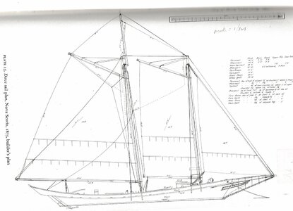
Chapelle provides a fairly well detailed rigging plan containing dimensions for all the masts and booms:Fig 52 rig plan.jpeg

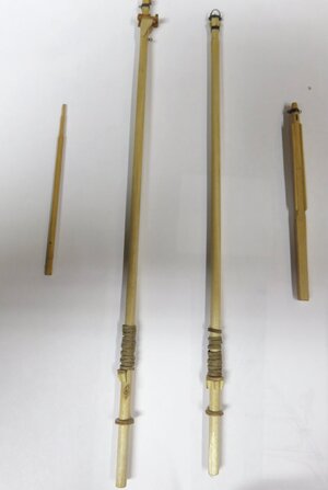
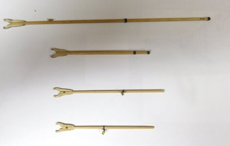
Additional details regarding construction and shape of the masts and booms were provided in the Appendix to the book. Mast hoops were made from strips of brown paper bag wrapped around a dowel and glued to form a ring.Fig 53 Masts.jpeg
Fig 54 booms.jpeg

Chain plates were cut from a 1/16'”wide brass strip, and the dead eyes were attached by wrapping them in a piece of copper wire and then soldering the tail end to the back of the chain plate.
Fig 55 deadeyes.jpeg

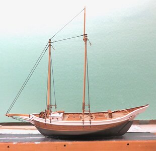
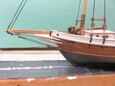
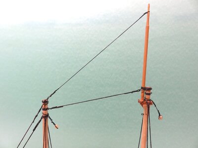
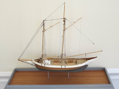
Rigging sizes ware not in the plans. I selected a diameter for the heaviest piece of standing rigging, the fore stay, that looked appropriate for the scale of the model, and then sized all of the other pieces of standing rigging proportionately. The model with the standing rigging complete is shown below along with details of the bowsprit rigging and rigging at the mast tops. I did not have chain of the right size for the bobstay so used rigging line instead.
Fig 56 stndg rig.jpegFig 57 bowsprit rig.jpegFig 58 tops rig.jpeg
 
My Congratulations for finishing this great model
 
Thanks for you kind comments during this build. I'm about to start my next project, a Hudson River sloop, with plans from the book by Paul Fontenoy titled, appropriately, "The Sloops of the Hudson River". I think I'll just post the pictures when I'm done.
 
Back
Top