• LUCZORAMA SHIPWRECK SCAVENGER HUNT GIVEAWAY. 4 Weeks of Fun • 1 Legendary Prize ((OcCre’s Fram Ship)) • Global Crew Welcome!
    **VIEW THREAD HERE**

Drawing help

Joined
Jul 10, 2021
Messages
1,718
Points
438

Location
Vancouver Island
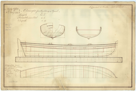
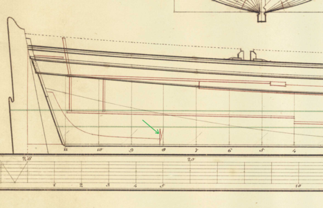
I'm building a 1:48 yawl for the Discovery1789. I'm about to install the keelson and noticed something on the drawing I don't understand. The drawing is ZAZ7128 if you want to see the whole thing. On the picture the green arrow is pointing at something that looks like draftsman shorthand. Can anyone explain what he is trying to indicate? It kinda looks like a cross section or something but I dunno :)

26_ft_Yawl_RMG.png
 
Are you suggesting it's a mistake? I never showed it but the same thing is at the bow at the aft end of the stemson. Here's the whole drawing. I don't think there would be two mistakes.


26_ft_Yawl_RMG_J0921.png
 
I assume, that this a very special information, or maybe even a error in this drawing.
Looking at all other 26ft yawl drawings - they are all more or less the same, but do not show this line.
So I would cancle this information as not important for your model - just use another drawing as basis
 
So I'm pretty new at some of this stuff but I did take some drafting a long time ago. Could it be that since he is showing frames with a single vertical line, the second vertical line with the "X" in between them is just showing the thickness of the frame so the part would end there by butting up against the frame, rather than go through the frame to the other side?
 
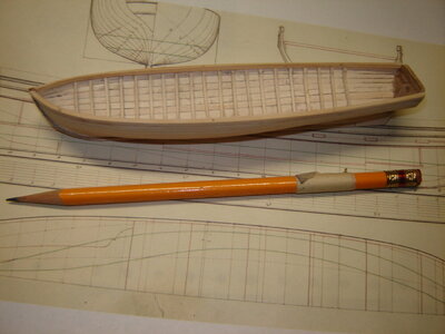
Thanks guys, every bit helps. Like Uwe says it's probably not important, especially at this scale. Here it is so far. This is at least two weeks work. It's looking like the Discovery may have had five boats and this is the biggest so I'll have to cut myself some slack when it comes to scantlings.


DSC04729.JPG
 
It could also be that the draftsman did not want to draw the entire keel section as it might take away from the water line details and also the X might represent the thickness of the keel. In architecual drawings a square or a rectangle with an X inside usually means showing the END of the lumber cut. But, I think you all have it covered by now.
 
I think Donnie is right, the line for the top of the keelson has been omitted for clarity,or the thickness of frames as wrote Corsair
Tom
 
Last edited:
I'm not sure of that. If you look at the cross section(top right) drawing the keelson you can see that the keelson is just a flat plank that doesn't extend as high as the "X" that we're looking at. It's close so I may be wrong. Well, I can always be wrong :)
 
I think it is a 'line break' - to allow a further view that would have been obscured had the full length of the keel been drawn in. We use 'Z' breaks similarly today....
 
That's kinda what I was thinking but then they(he) didn't drawing anything in. Like, nothing is/would be obscured if he had drawn in the keel, frames and keelson. Draughtsman's shorthand I guess. I'm reading a bunch of boat's threads over on MSW and the consensus is that these boat drawings are incomplete a lot of the time. Everyone knew how to build a boat so they just needed a general idea of the shape. I dunno.
 
Don, to me this looks like a sort of a tie down frame as it appears to cover the end of both the transom knee and the the stem. They appear too be just fore and aft of their corresponding frames, if you look at the drawing carefully. Remember this is a flat keel which is not really the bearer of great strength and a but joint into a frame would not carry a great amount of strength on the flat keel. Now place a fitted, heavier frame over the transom knee end and the stem would add a lot of strength to the keels twisting stress at these two critical points on the vertical joints on the flat keel. This is my opinion based on my Nautical Design knowledge, as at one point in time I studied Naval Architecture. Hope you can understand what I'm trying to explain the drawing as I see it. Hope this helps Don.
 
Are you suggesting it's a mistake? I never showed it but the same thing is at the bow at the aft end of the stemson. Here's the whole drawing. I don't think there would be two mistakes.


View attachment 357360

Thanks guys, every bit helps. Like Uwe says it's probably not important, especially at this scale. Here it is so far. This is at least two weeks work. It's looking like the Discovery may have had five boats and this is the biggest so I'll have to cut myself some slack when it comes to scantlings.


View attachment 357535
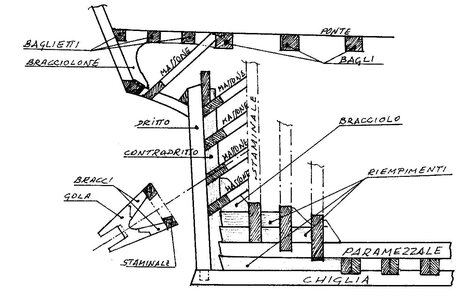
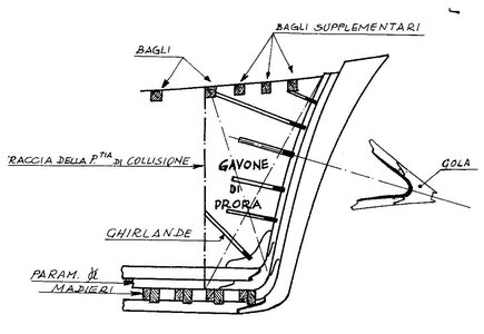
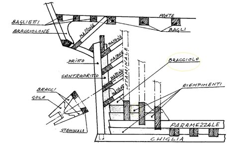
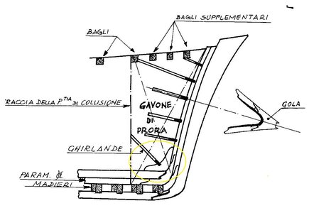
Counterstarboard, bow and stern armrest drawn on the drawing you posted
 
Don, to me this looks like a sort of a tie down frame as it appears to cover the end of both the transom knee and the the stem. They appear too be just fore and aft of their corresponding frames, if you look at the drawing carefully. Remember this is a flat keel which is not really the bearer of great strength and a but joint into a frame would not carry a great amount of strength on the flat keel. Now place a fitted, heavier frame over the transom knee end and the stem would add a lot of strength to the keels twisting stress at these two critical points on the vertical joints on the flat keel. This is my opinion based on my Nautical Design knowledge, as at one point in time I studied Naval Architecture. Hope you can understand what I'm trying to explain the drawing as I see it. Hope this helps Don.
I think I understand what you are saying and that makes sense. It's too bad it wasn't shown on the other views but with 200+ year old drawings you take what you can get. There are a bunch of ships boat drawings on NMM so maybe I'll spend some time looking at them.
 
Counterstarboard, bow and stern armrest drawn on the drawing you posted
Hi Frank. I'm not understanding. I think "armrest" may be a bad translation. It also sounds like you were showing a change that you made on the drawing. Did you mean to have a another drawing attached?
 
Don, I think if you look at the upper right hand cross section drawing, look at the red line drawing just above the keel and there appears to be a larger section in red that appears to be a heaver frame section resting the keel, just what appears to be a seat outline, the double red line, and the lower double red line appears to be the floor boards and the frame would also be the support for the floor boards, both fore and aft. This is the way I see the representation on the drawing. Mikeyt
 
Hi Frank. I'm not understanding. I think "armrest" may be a bad translation. It also sounds like you were showing a change that you made on the drawing. Did you mean to have a another drawing attached?

sss.jpg

qqq.jpg
 
Back
Top