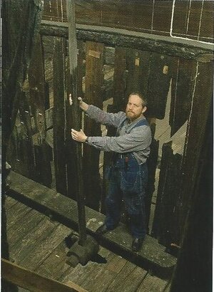
I’m watching Fred. He’s got some crazy moves.
-

Win a Free Custom Engraved Brass Coin!!!
As a way to introduce our brass coins to the community, we will raffle off a free coin during the month of August. Follow link ABOVE for instructions for entering.
-

PRE-ORDER SHIPS IN SCALE TODAY!
The beloved Ships in Scale Magazine is back and charting a new course for 2026!
Discover new skills, new techniques, and new inspirations in every issue.
NOTE THAT OUR FIRST ISSUE WILL BE JAN/FEB 2026
You are using an out of date browser. It may not display this or other websites correctly.
You should upgrade or use an alternative browser.
You should upgrade or use an alternative browser.
Emma C. Berry 1:32 PoF by Model Shipways
- Thread starter fred.hocker
- Start date
- Watchers 28
On second thought Paul I think I’ll move a couple of seats over.Renowned pole dancer...
View attachment 324520
Sorry Fred. I'll go back to my seat now and be quiet.
- Joined
- Jul 12, 2021
- Messages
- 141
- Points
- 143

Yeesh, you guys....
- Joined
- Jul 12, 2021
- Messages
- 141
- Points
- 143

The kit is designed as true plank on frame, with components sized similar to the originals. The frames, for example, are sized at 5” square (5/32” at scale). The framing arrangment represents a typical practice in New England yards in the 19th century. Each frame was made of two half-frames, which meet over the keel. In some cases, these were grown crooks, but in smaller vessels they might be steam bent. At every other frame pair, the joint at the centreline is reinforced with a short floor timber. In the middle of the vessel, these are of similar scantlings to the half frames, but towards the stern they are deep triangular chocks notched over the deadwood.
The kit provides all of these components as laser-cut pieces. Each frame is shown on the drawings, so that the pieces can be aligned. After a frame is assembled and bevelled, it is clamped to the framing jig, which slides on rails parallel to the strongback. This holds the frame vertical and square to the keel while it is glued in place.
This replicates the full-scale building practice accurately (which is cool), but I am unsure how effective it is for a model. At full size, the weight and stiffness of the frame gives it stability while it is being set up and braced, and it has enough inertia to resist being dubbed with adzes, bored for treenails, and pounded with hammers. At full scale, there is also enough room to work under the hull, boring holes and fairing the frames. I see no reason that this model could not be built upside down, with a framing jig at the sheer, which would then provide much better stiffness and access for fairing and planking, as well as assuring good alignment with minimum fuss. If I were scratchbuilding, that is how I would do it. But we’ll see how this goes.
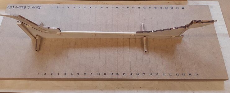
Before the frames can be set up, there is a fair amount of layout work. The frame locations have to be marked and lines square to the centreline drawn across the building board, as a reference for placement. I had to do this several times to get an acceptable result, as I discovered that the frame locations are not marked very consistently on the plan, and the plan does not match the laser-cut backbone timbers exactly. The nominal room and space for the frames is 19” (19/32” at scale), but the total calculated distance between the after faces of floor timbers 4 and 16 (the frames resting directly on the keel) is slightly longer than the space available between the bow and stern deadwoods, and the locations as drawn on the plans vary a little from frame to frame. One can either use dividers to lay out perfectly even intervals, which will be something like 18.87/32”, or do as is sometimes done at full size, putting all of the discrepancy in one place where it will have the least effect. I chose this option, making the space between frames 12 and 13 (the midships frame and the one just forward of it) short by 1/16”. These two frames are nearly identical in shape, so it should not affect the fairness of the framing significantly.
This is a recurring issue with the kit. The plans are not as carefully drawn as I would like, with a lack of agreement between views, and some discrepancies between the drawings and the kit parts. Partly this is the result of shrinkage of the wood parts across the grain, but partly it is inconsistency in the drawing.
The framing jig rides on rails made from 3/16” square strip, glued or nailed down to the building board. These require care to get them straight and square, at the right spacing so that the jig will run smoothly, without distortion.

- Joined
- Jul 12, 2021
- Messages
- 141
- Points
- 143

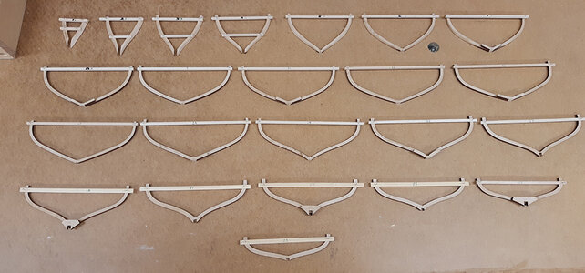
The components of each frame are glued together on top of the drawing to make sure that the spacing and alignment are correct (reminds me of building balsa airplanes as a kid). The heads of the half-frames are connected by a temporary cross spall. Although the kit provides some 1/8” strip which can be used for the cross spalls on the frames, there is not really enough. Fortunately I have a bottomless supply of stripwood. When I was helping D’Agostini with the design of the Vasa kit, they gave me a full Sovereign of the Seas kit so that I could see how their process works. I have no intention of ever building this, but it is a handy supply of pretty good quality material, including a lot of bamboo strip that is perfect for spalls.
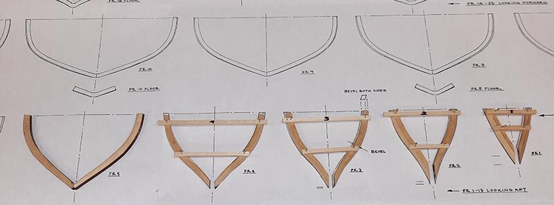
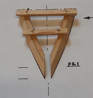
At the ends of the hull (frames 1-4 and 24-25) the half-frames do not meet at the center, but butt against the apron or horn timber. A second spall is used near the lower ends for frames 1-4, but the horn timber and rudder trunk assembly completely block the center plane at the stern. I will fit these frames later, to battens run between the other frames and the transom.
The instructions have you bevel the planking and ceiling faces of the frames, at least roughly, before setting them up on the keel. This is also a reflection of how real vessels are built, using a big shipsaw, which is a bandsaw with the upper wheel mounted on a track so that a continuously changing bevel can be cut, removing the majority of the material. To do this, the bevel at several points along the frame has to be measured carefully, either from the drawings or from the vessel itself. With the kit, the bevels are indicated on the drawing of the laser-cut parts, and can be laid out directly and the inboard and outboard faces whittled or filed to shape. I discovered when laying out the bevels that the method for creating the bevel line may not be technically accurate, so when cutting them I left a little over the line for later fairing. I carved the bevels with a knife, to get a crisp, flat surface, but I could have used small rasps and files.
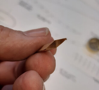
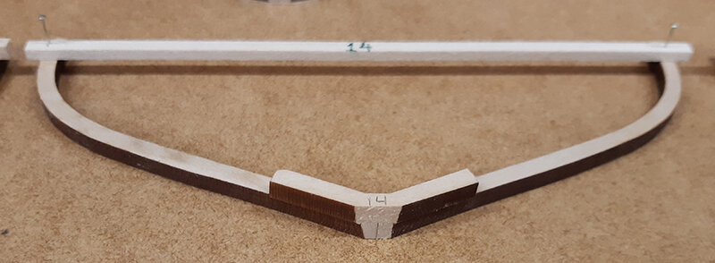
Once I got into making the frames, I only bevelled frames 1-7. The bevels on the rest are so slight, and the deviation from the drawings so noticeable that I left all the wood for fairing. Making up the frames is pretty quick, since there are only two or three parts for each one. The join at the centreline on the ones without floor timbers seemed pretty fragile to me (end-grain glue join with small surface area), so I added a thin layer of wood across the joint on these frames. It can be carved away later if I decide to leave the framing exposed.


At the ends of the hull (frames 1-4 and 24-25) the half-frames do not meet at the center, but butt against the apron or horn timber. A second spall is used near the lower ends for frames 1-4, but the horn timber and rudder trunk assembly completely block the center plane at the stern. I will fit these frames later, to battens run between the other frames and the transom.
The instructions have you bevel the planking and ceiling faces of the frames, at least roughly, before setting them up on the keel. This is also a reflection of how real vessels are built, using a big shipsaw, which is a bandsaw with the upper wheel mounted on a track so that a continuously changing bevel can be cut, removing the majority of the material. To do this, the bevel at several points along the frame has to be measured carefully, either from the drawings or from the vessel itself. With the kit, the bevels are indicated on the drawing of the laser-cut parts, and can be laid out directly and the inboard and outboard faces whittled or filed to shape. I discovered when laying out the bevels that the method for creating the bevel line may not be technically accurate, so when cutting them I left a little over the line for later fairing. I carved the bevels with a knife, to get a crisp, flat surface, but I could have used small rasps and files.

Once I got into making the frames, I only bevelled frames 1-7. The bevels on the rest are so slight, and the deviation from the drawings so noticeable that I left all the wood for fairing. Making up the frames is pretty quick, since there are only two or three parts for each one. The join at the centreline on the ones without floor timbers seemed pretty fragile to me (end-grain glue join with small surface area), so I added a thin layer of wood across the joint on these frames. It can be carved away later if I decide to leave the framing exposed.
- Joined
- Jul 12, 2021
- Messages
- 141
- Points
- 143

When assembling each frame set, I discovered that the half-frames are shorter (by up to 1/8”, 4 inches in scale) than the drawings, and almost all differ slightly in curvature from the plans (flatter-floored). This looks like the result of some shrinkage of the wood across the grain after laser cutting, and will result in a vessel that is slightly lower at the rail and flatter in the bottom than the drawings, unless one wants to bin the laser-cut frames and scratch build new ones. I am not that ambitious, and the error at least seems to be consistent, so I will live with it.
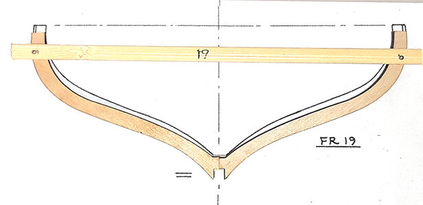
I discovered that the traditional technique of pinning the spall in place has its drawbacks. The upper ends of the frames abaft nr. 4 are all short grain, which tends to split even with the smallest pins I have. I got tired of gluing the ends back on, and eventually used spots of CA glue instead, after testing to make sure I could remove them again.
There is also the matter of the results of laser cutting. This leaves a very slight bevel on the parts to begin with, and Model Shipways have laid out the half frames so that the two parts are oriented the same way, rather than as mirror images (it saves space, I suspect). This means that the bevel on one half goes the opposite way from the bevel on the other half, and so the outer profile of the two parts is not identical. Another reason to leave a little extra for fairing.
- Joined
- Jul 12, 2021
- Messages
- 141
- Points
- 143

The frames are set up vertically, with the keel oriented on the strongback so that it is rising towards the bow. The surface of the bottom of the frame, where it sits on the keel, is thus not square to the faces of the frame. It is a consistent angle (a hair over 87o), but the surface is so small that it is difficult to measure it accurately on the frame. Instead, I made a jig to plane this quickly and consistently. Using this, I could set up each frame (numbers 5-16) in the jig, check that it was square to the centreline, and quickly plane the bottom bevel with a block plane. It took longer to make the jig than plane the frames! My son, a software engineer, tells me that this kind of “making a tool to make a tool” rabbit hole is called “yak shaving” in his world.

One of the options on a plank-on-frame model is to leave the planking off to expose the framing. One can go full admiralty style and leave the whole bottom unplanked, or leave an open patch on one side. I want to build a full cabin interior aft, and leaving the planking off would be a way to show it, as well as showing off the wet well construction. I think I will make the cabin accessible by having the trunk removable. It sits on level sills with corner posts, so it will be straightforward to give it a stable location.
Leaving the planking off on something so lightly framed presents an extra challenge, as the tension in the fully planked side may distort the unbalanced structure if the planks are not steamed and bent exactly to shape. I think I will plank fully, and have the interior visible through the hatches. GuyH solved this on his build by using full length planks, but not gluing them to the frames where he would later cut them away – very clever.
There, all the frames (except 24 and 25) are made up. Time to start setting them up on the keel.

- Joined
- Jul 12, 2021
- Messages
- 141
- Points
- 143

There will be a short hiatus in the build, as I am in the US for the next three weeks working on a real ship. I am a volunteer with the sailing ship Kalmar Nyckel, a recreation of the ship that took the first Swedish and Finnish colonists to America in 1638. I will be scraping painting and carrying out engineering tasks while the ship is hauled out at Mystic Seaport - look out for a picture or two.
Fred
Fred
Forgive me if this is out of line, but I wonder if you've matched the actual half frames to the drawings in the best way possible. There certainly may be (probably are) errors due to manufacturing and shrinkage, but I don't think it's as large as your drawing represents. It seems to me that the overall height and width are the most important factors, in getting a representative hull shape, and while you've matched the width fairly well (using the inner edge of the frame), the top is way off, as you say. And it appears that the half frame width (thickness, in the above view) at the top is somewhat wider than that on the drawing as well. At the very high aspect ratio of width to height, a small width change results in a large height change.When assembling each frame set, I discovered that the half-frames are shorter (by up to 1/8”, 4 inches in scale) than the drawings, and almost all differ slightly in curvature from the plans (flatter-floored). This looks like the result of some shrinkage of the wood across the grain after laser cutting, and will result in a vessel that is slightly lower at the rail and flatter in the bottom than the drawings, unless one wants to bin the laser-cut frames and scratch build new ones. I am not that ambitious, and the error at least seems to be consistent, so I will live with it.
View attachment 324616
I copied this photo into my paint program, and made a layer of the actual half frame outline only in red, and rotated it (about 1.77 degrees) to where I feel it matches the drawing better. Yes, it's slightly narrower at the top, at least on the inside (a bit less so on the outside), but I think an overall much better representation of the hull shape:
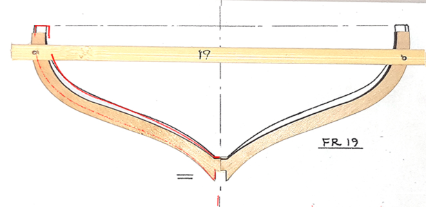
The moved/rotated frame is shown in red, and as you can see, the inner contour is now quite close (no outer contour was shown for me to compare), with just a small change in the width at the top. I think this would give more success in duplicating the hull shape as closely as possible. If you agree, it would still be possible to make such a change (which would apply to all the half frames). If not, then carry on, I'm sure it will be a lovely model regardless. Good luck!
BTW, good work on the jig with help from your engineer son. As an engineer son myself, I've never heard of "yak shaving", but back in my generation I'm sure we called it something different. (Just researched it: The term "yak shaving" was coined in the early 90s after a 1991 episode of The Ren and Stimpy Show. As I graduated in 1965, I would be blissfully ignorant of the term.
- Joined
- Jul 12, 2021
- Messages
- 141
- Points
- 143

Hi Signet, I understand what you mean, and I investigated this when I was making up the frames. What I discovered was that I could either match the width of the drawing or the height from keel to rail, but not both. Since the more vertical frames at the bow are less affected by shrinkage, due to grain direction, I looked at those first. They are clearly shorter than the drawing shows, about the same amount, so I chose to match the width of the frame and live with the slightly shorter height. I also discovered that by matching width, I got a better fit in overall shape. This may suggest that some of the problem is not shrinkage, but a basic discrepancy between the drawings and the laser cut parts.Forgive me if this is out of line, but I wonder if you've matched the actual half frames to the drawings in the best way possible. There certainly may be (probably are) errors due to manufacturing and shrinkage, but I don't think it's as large as your drawing represents. It seems to me that the overall height and width are the most important factors, in getting a representative hull shape, and while you've matched the width fairly well (using the inner edge of the frame), the top is way off, as you say. And it appears that the half frame width (thickness, in the above view) at the top is somewhat wider than that on the drawing as well. At the very high aspect ratio of width to height, a small width change results in a large height change.
I copied this photo into my paint program, and made a layer of the actual half frame outline only in red, and rotated it (about 1.77 degrees) to where I feel it matches the drawing better. Yes, it's slightly narrower at the top, at least on the inside (a bit less so on the outside), but I think an overall much better representation of the hull shape:
View attachment 325892
The moved/rotated frame is shown in red, and as you can see, the inner contour is now quite close (no outer contour was shown for me to compare), with just a small change in the width at the top. I think this would give more success in duplicating the hull shape as closely as possible. If you agree, it would still be possible to make such a change (which would apply to all the half frames). If not, then carry on, I'm sure it will be a lovely model regardless. Good luck!
BTW, good work on the jig with help from your engineer son. As an engineer son myself, I've never heard of "yak shaving", but back in my generation I'm sure we called it something different. (Just researched it: The term "yak shaving" was coined in the early 90s after a 1991 episode of The Ren and Stimpy Show. As I graduated in 1965, I would be blissfully ignorant of the term.)
The image I provided has a fair degree of parallax, so appears to exagerate the effect. When I took the image, I had aligned the outer edge of the frame as closely as possible to the outer edge drawn on the plan over as much of the length as possible. The closest fit was found when matching the overall width. If I rotated as you suggest, I could match the height, but would then not only get a narrower frame but the bilge curvature would end up out of line, and would not fair over the length as well.
Fred
The frame illustrated has the largest error, for most of the other frames the discrepancy in curvature is much less, especially on the inboard face.
Hi Fred,
I love to see that you and also Ab Hoving who are proffesionally involved in the things we love to do as a hobby are still involved in model building as a hobby yourselves.
Especially in willing to help others, for us that is of great help, as I experienced myself with the help of Ab in recreating a possible shape of the Ghost ship which will be my next project.
Looking forward to the rest of your build of this interesting small model.
Looking also forward to your experiences onboard Kalmar Nickel, we are all eager to learn and ofcourse share some jokes from time to time.
FredHi Signet, I understand what you mean, and I investigated this when I was making up the frames. What I discovered was that I could either match the width of the drawing or the height from keel to rail, but not both. Since the more vertical frames at the bow are less affected by shrinkage, due to grain direction, I looked at those first. They are clearly shorter than the drawing shows, about the same amount, so I chose to match the width of the frame and live with the slightly shorter height. I also discovered that by matching width, I got a better fit in overall shape. This may suggest that some of the problem is not shrinkage, but a basic discrepancy between the drawings and the laser cut parts.
The image I provided has a fair degree of parallax, so appears to exagerate the effect. When I took the image, I had aligned the outer edge of the frame as closely as possible to the outer edge drawn on the plan over as much of the length as possible. The closest fit was found when matching the overall width. If I rotated as you suggest, I could match the height, but would then not only get a narrower frame but the bilge curvature would end up out of line, and would not fair over the length as well.
Fred
The frame illustrated has the largest error, for most of the other frames the discrepancy in curvature is much less, especially on the inboard face.
I was a draftsman a long time ago and we would have issues with paper expanding with humidity. It was the cheap blue ray paper and it was when we scaled from the copied drawings. Just throwing that out there but it sounds like you are working through the issue.
Carry on !
Don
- Joined
- Jul 12, 2021
- Messages
- 141
- Points
- 143

Hej Maarten,Hi Fred,
I love to see that you and also Ab Hoving who are proffesionally involved in the things we love to do as a hobby are still involved in model building as a hobby yourselves.
Especially in willing to help others, for us that is of great help, as I experienced myself with the help of Ab in recreating a possible shape of the Ghost ship which will be my next project.
Looking forward to the rest of your build of this interesting small model.
Looking also forward to your experiences onboard Kalmar Nickel, we are all eager to learn and ofcourse share some jokes from time to time.
If you have any questions about the Ghost Ship (I assume you mean the 1660s Dutch fluyt sunk in the middle of the Baltic), I am also happy to help. I was one of the lead archaeologists on that project. You might also contact Niklas Eriksson, who has been working on a reconstructed hull shape for the vessel.
Here at Kalmar Nyckel I am part of the engineering team. We are replumbing the engine room, overhauling and optimizing the bilge and fire pump systems, as well as changing a propeller shaft. Most of the drydock crew are busy on the outside of the ship, scraping and painting as well as renewing caulking below the waterline. We had a half-day off yesterday (because of the Labor Day holiday) so some of us went sailing around in the Mystic River in one of the Seaport's small boats, a Wood's Hole catboat with a sprit rig. A lovely afternoon.
Nyckel will go back in the water next week, after I fly off to a conference in Halifax, Nova Scotia.
Fred
- Joined
- Jul 12, 2021
- Messages
- 141
- Points
- 143

Hej Don,Fred
I was a draftsman a long time ago and we would have issues with paper expanding with humidity. It was the cheap blue ray paper and it was when we scaled from the copied drawings. Just throwing that out there but it sounds like you are working through the issue.
Carry on !
Don
I wondered about that as well, since the plan sheets do not want to lie completely flat. I did some cross-checking of the drawings themselves, as well as matching parts against the drawings. There are lots of small discrepancies, but overall the drawings seem to agree with each other, and parts which disagree almost always do so across the grain, where they are always too short.
The nice thing is that now that I have most of the frames erected amidships, the shapes line up fair (pictures to follow).
Fred
That is true, while a different alignment may have worked on the frame illustrated, if the much more vertical frames also had the height difference, then that is a completely different case. I'm sure with so many parts affected, you took all into account and made the best decision for the model in general. If the entire assembled hull frame system is still 1/8" or so short, it may also be possible to add a 1/8" square stripwood longitudinally to bring the top to the correct height. But I'm sure you've already thought of that or have another mod in mind, or find that none is really required.The frame illustrated has the largest error, for most of the other frames the discrepancy in curvature is much less, especially on the inboard face.
I love posts like yours describing problems, and then follow up with how to get around them, because we all have to do that.
Hej Fred,Hej Maarten,
If you have any questions about the Ghost Ship (I assume you mean the 1660s Dutch fluyt sunk in the middle of the Baltic), I am also happy to help. I was one of the lead archaeologists on that project. You might also contact Niklas Eriksson, who has been working on a reconstructed hull shape for the vessel.
Here at Kalmar Nyckel I am part of the engineering team. We are replumbing the engine room, overhauling and optimizing the bilge and fire pump systems, as well as changing a propeller shaft. Most of the drydock crew are busy on the outside of the ship, scraping and painting as well as renewing caulking below the waterline. We had a half-day off yesterday (because of the Labor Day holiday) so some of us went sailing around in the Mystic River in one of the Seaport's small boats, a Wood's Hole catboat with a sprit rig. A lovely afternoon.
Nyckel will go back in the water next week, after I fly off to a conference in Halifax, Nova Scotia.
Fred
That sounds like a 21st century docking with a 17th century vessel. Being a seagoing engineer myself in the past it sounds more then familiar.
I have tried to contact Niklas and used his drawings and written papers in my reconstruction effort, but did not get in touch with him yet.
I am mainly looking for the video material.
See my reconstruction work on the ship here.
A Dutch Fluyt in shell first, reconstructing the "Ghost ship" scale 1:36
For a long time I already want to build a Dutch fluyt and had been looking for the best possible candidate. The shape of the fluyt is extraordenary and directly recognizable with its bollow stern, the Jelo of ships. It was the workhorse of the 17th century when the Dutch dominated shipping in...
shipsofscale.com
Many thanks for your offer, enjoy your remaining time in the USA and your flight back to Sweden.
- Joined
- Jul 12, 2021
- Messages
- 141
- Points
- 143

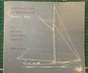
A great book, with lovely illustrations. Will had a good eye for the important details.


