• Ships of Scale has incorportated an extra level of security when you log In. Please follow on-screen prompts to acknowledge that you are not a robot via a "Check Box" or a "Pictorial Check Box Puzzle". This is needed due to higher level of AI Activity Security.
  • SUBSCRIBE TO SHIPS IN SCALE TODAY!

    The beloved Ships in Scale Magazine is back and charting a new course for 2026!
    Discover new skills, new techniques, and new inspirations in every issue.

    NOTE THAT OUR NEXT ISSUE WILL BE July/August 2026
  • Win a Free Custom Engraved Brass Coin!!!
    As a way to introduce our brass coins to the community, we will raffle off a free coin during the month of August. Follow link ABOVE for instructions for entering.

Emma C. Berry Build Log

Joined
Oct 5, 2026
Messages
11
Points
28

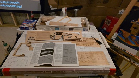
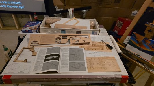
Start off by saying I have never built a model ship but am familiar with balsa planes. I always wanted to build a model ship, but never committed. Recently I found a kit for the Emma C. Berry by Model Shipways on Facebook Marketplace. I really liked that this model had the exposed siding and drydock diorama setting. I also liked that it was only $30! This was too nice of a kit for me not to try this hobby.

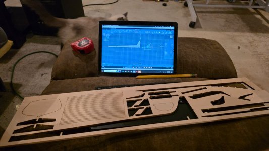
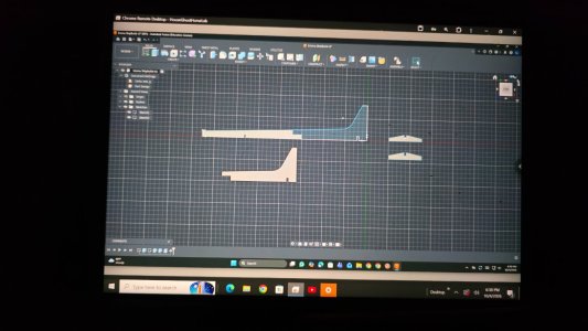
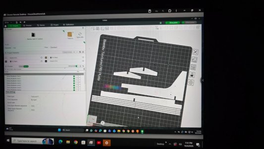
Buying this second hand it appears there are a few missing pieces but otherwise all there. The only pieces missing was for the supporting structure that the ship is built upon. Luckily I was able to design and 3D print replacement parts by measuring the spaces the parts used to be and recreating in Fusion360.

I am now ready to start construction from where the previous owner left off.

20261004_175745.jpg

20261004_175745.jpg

20261004_175755.jpg
 
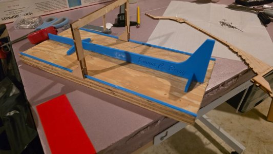
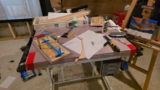
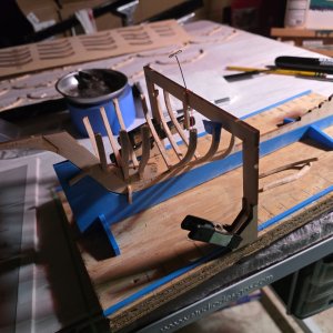
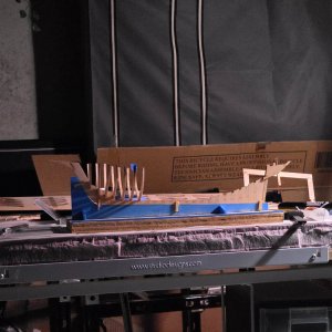
Got the new building stand that the ship will be built on printed and installed.

This kit uses a sort of drydock that gets built first to then build the ship on. I decided to take the time and put the name of the ship on the stand since I had to make it anyway.

20261004_180639.jpg

20261004_183040.jpg

20261004_193149.jpg

20261005_181028.jpg
 
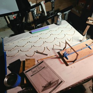
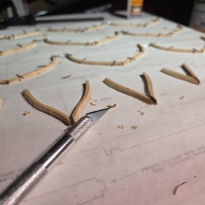
Now that the 'drydock' is complete and what will be the ship is in place, I can start focusing on the frames ligned up and bevels cut. Not sure if I did good on the bevel cuts yet at this point, but seen to match the plans. I worry I may have cut away too much at times but they seem to line up with the plans so we will see.

Next step is to put the frames on using my crane and track system. Should be exiting!

20261005_181023.jpg

20261011_165803.jpg

20261011_173950.jpg
 
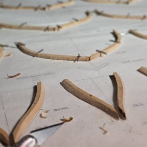
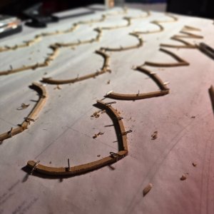
I don't know how I feel about my decision, but I grew tired of cutting the bevels by hand and decided to cheat by using a Dremel with a cylindrical sanding drum to shape the bevels instead. Oh boy, what an upgrade! I just had to give a small sand afterwards and be mindful of the Dremels rotation when nearing the edges (I learned this the hard way.

The downside to this method is it seems to roughen up the balsa more than expected and left a "fuzzy" texture. I used a very fine sandpaper to meditate the affect but nothing looks the same as actually cutting the wood. That being said, I could never get the consistency and even/level cuts as I did with the Dremel. Something for me to think about more for future builds I guess.

For context, the instructions stated that the inside/inboard sides of the frames can also be beveled and I opted to do so. One of the things I loved about this model was the exposed interior and wanted a realistic look. I didn't want that laser cut look on the exposed frames and so I took advantage of the beveling to remove the dark/burnt edges. This was time consuming, but worth it. The Dremel was a must in my opinion, otherwise I wouldn't have done this.

The instructions are clear in reminding me the exposed frames need bevels that are aesthetically pleasing (obviously) but say that the same should be done for the interior bevels if a small room is desirable (not as obvious, at least not to me.

This model having the open frame work and exposed frames, I decided to put in a miniature room that accurately shows the living bildge/storage for lobsters/catch that the Emma C. Berry had. I want to put in a small "lantern" in this room that will disguise an LED Diode. This will flicker, like a flame in a lantern, when the room the model is in goes dark. This will be driven by a light sensitive sensor and an esp32 to act as the brains. I will also have a 'lantern' someplace else, but can't decide on the location. Maybe on the ships deck? Maybe on the scaffolding next to exposed side of the hull?

I will have light coming out of the ship from two openings from inside the miniature room, the first from the exposed hull opening and the second from the exposed deck planking that opens the ceiling of the room. I am thinking that putting additional 'lanterns' in the deck or scaffolding would wash out the light coming from inside the ship and ruin the affect. Maybe putting a lantern on the opposite side of the ship, away from the opening, on the ground next to the ship? This could be near the bow to light up the ships name and trim work up there and would also make sense to provide light for the planking stacked on the ground.

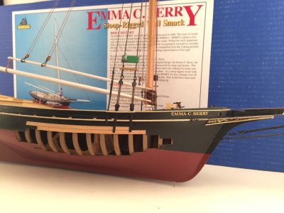
I put a few reference pictures of others finished models in case people are not familiar with this model.
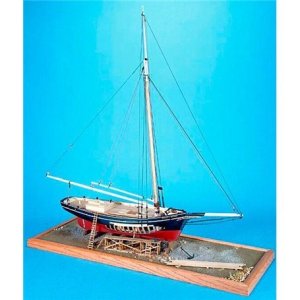
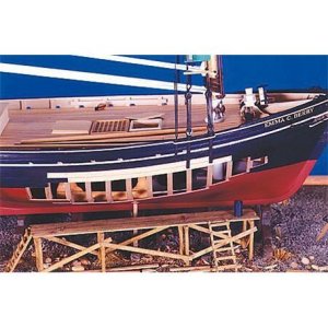
1-32-emma-c-berry-lobster-smack.jpg

1-32-emma-c-berry-lobster-smack (1).jpg

611LOZLSgbL.jpg
 
I also bought this kit second hand, and have it sitting in my stash. I look forward to your build log. I'll pull up a chair.
If you are missing parts, let me know and maybe I can generate a 3D model for it (if that is helpful).
 
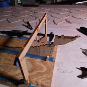
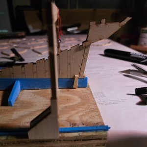
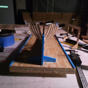
Got started attaching frames, I put on a few methods to try to keep plum but it was hit or miss on if it was useful. Measurements on both sides of the track turned out to be critical. Frames seem to be about 15mm apart on the nose, makes spacing easy.

I didn't understand that the first four frames had a sort of drop as you installed them so stupidly just made them all level assuming that would be correct because the first frame was. Luckily I pulled the frames away and reinstalled before the glue cured. Seems to just kind of be a guess here, I did what I thought looked right. The only references I had are the distance from frame to center based off plans and measured using digital calipers. I think those were the hardest to understand, but think it is smooth sailing from here (pun intended).

I'm not sure how the 'floors' work in the build. There is a YouTube video that shows the floors pieces being installed beside the frame on the keel but am not sure what purpose that serves. I will figure that part out next session.

20261012_125731.jpg

20261012_125736.jpg

20261012_152149.jpg

20261012_154222.jpg
 
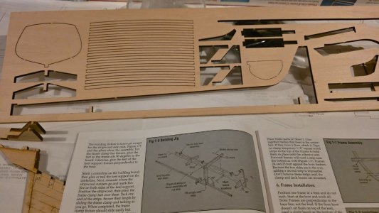
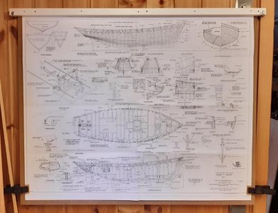
Oof, just discovered I am missing a whole sheet!

Time to put on my binoculars and see what I have messed up so far! I figured that there was something missing, this has been seeming impossible!

Looks like I have sheets 1,3 and 4 with this being sheet 2..

Berry 1-2 comp.jpg

Berry 1-2 comp.jpg
 
Requesting if anyone can provide a better picture of this sheet?

Or know how I can obtain a new copy?

I need something with a little higher resolution.
 
I think you're supposed to attach a spacer at the top of the frames before gluing to the keel, to prevent them from spreading out. The floors will also substantially strengthen the joint between frame and keel. If you haven't already, definitely take a look at other build logs for this model, I believe there are a few.
 
Back
Top