


• Ships of Scale has incorportated an extra level of security when you log In. Please follow on-screen prompts to acknowledge that you are not a robot via a "Check Box" or a "Pictorial Check Box Puzzle". This is needed due to higher level of AI Activity Security.
  • SUBSCRIBE TO SHIPS IN SCALE TODAY!

    The beloved Ships in Scale Magazine is back and charting a new course for 2026!
    Discover new skills, new techniques, and new inspirations in every issue.

    NOTE THAT OUR NEXT ISSUE WILL BE July/August 2026
  • Win a Free Custom Engraved Brass Coin!!!
    As a way to introduce our brass coins to the community, we will raffle off a free coin during the month of August. Follow link ABOVE for instructions for entering.

Emma C. Berry Build Log

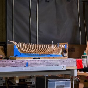
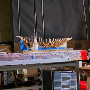
The ship has now been inadvertently stress tested, see picture below...

I am shocked that there was so little damage, this new glue I am using turned out to be a much needed upgrade.

I will be re-assembling the frames that broke apart and getting everything lined back up.

I have read a couple comments now stating that I should spend the time/effort to brace the frames and I have decided I will be taking this advice. I am lucky to have had all my frames hold shape so far (even post 'crash test' surprisingly) and I don't want to push my luck.

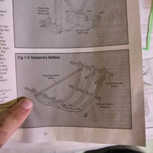
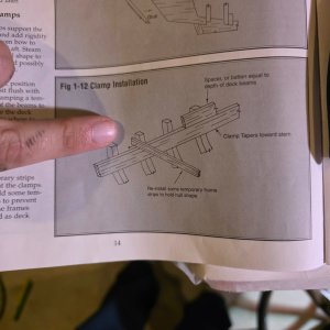
My main reason for not wanting to install braces was to prevent split frames, something I read in another log for the same kit. The other reason being how I would remove the braces without causing damage or misaligning everything. The instructions say to remove the braces to install the "Clamp" (a long stringer that attaches inboard of the frames) then the spacers/braces for the frames...

I find this confusing because now I am installing balsa strips along an unsupported hull because I won't be included supports for the frame spacing back in until AFTER this is complete. This seems counterproductive to me and figured I would just install the frame braces in after that was done to save effort and mitigate risk.

Hoping someone smarter than me can help me understand this a bit better.
20261013_141215.jpg

17919172650088673239435095700428.jpg

17919172927968594260703331683887.jpg
 
Good repair work! I wonder if it would be possible to slide the clamps into place without removing the majority of the cross-braces? I'd also suggest using a tiny dab of white glue instead of a pin, it can be easily removed later with alcohol.
 
Hi Guy, I enjoyed building this kit, and I am sure you will as well. I had some difficulty keeping all the frames square and level, even with the structure on the building board. My build log is attached, and if you have any questions, I'll try to remember what I did. It took me about 3 years, and I finished it several years ago. The last I knew, Emma Berry is at Mystic Seaport and out of the water for repairs.
Guy
 

Attachments

Haha! I recognize the plans I have hanging up in my workshop in your photo of Sheet 2! Hope your build is going well, I am a little stalled in the framing at the moment.

Fred
 
I had some difficulty keeping all the frames square and level
I see that issue crop up in most build logs for this kit.

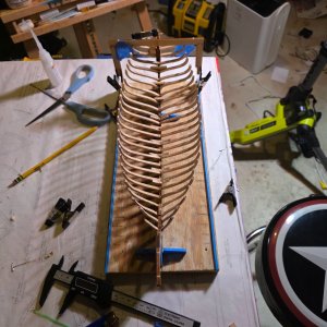
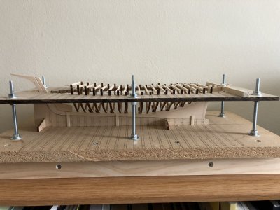
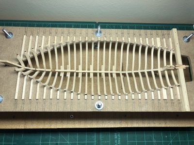
Knowing that the frames were fragile I built a framing jig to keep everything in line.

1792371211269.jpeg

I didn't bevel any of the frames before attaching them to the keel. The spreaders were removed and I sanded / faired the interior.

1792371394871.jpeg

All the interior work - false keel, clamps, ceiling, deck beams, lower cabin features, etc. were completed while the hull was in the jig. Afterwards the structure was quite strong, it was removed from the jig and the exterior was faired in preparation for framing, etc.

This alternative method worked well for me.

Guy008: Good luck with your build!!
 
That's really impressive! How did you fashion it?
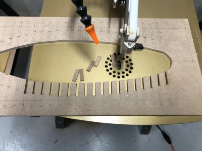
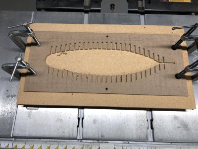
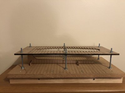
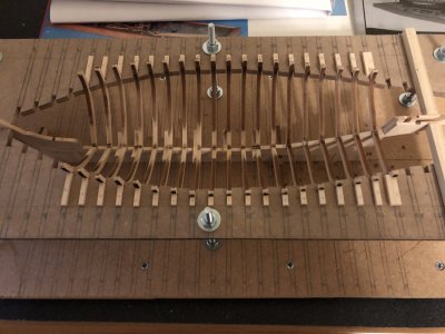
It was done in an ad hoc fashion based on similar setups I had seen for POF models. There were several things that had to be done precisely and others that were done less so that later needed to be shored up. What needed to be precise was a grid on the 1/4" fiber board that would be the main part of the jig. The centerline and perpendicular lines noting where each frame were drawn the board. Based on the plans, I chose a level for the board that all of the frames would come into contact / be supported by the board. The approximate locations were marked on both sides of the center line. A precise distance was noted for the stem slot. A hull like shape was cut out of the board - smaller than what would be needed later. This is part of the ad hoc nature! Slots allowing for the frames were cut in to the approximately noted locations. I tried to get the cuts reasonably close but cut a bit deeper in all cases.

1792379925278.jpeg

The comb jig board was then set on a larger / thick board that would become the building board. Six holes for bolts were drilled through both, and locations of the centerline and frames were transferred to the thicker board. I did make a frame under the building board with 1 x 2 lumber to keep it flat (and easier to pick up). The kit supplied keel jig was attached to the base / building board so the keel / stem / stern structure was in the correct fore to aft location. The comb board was then attached to the base with the bolts. It was important to have the comb portion of the jig at a constant height above the base board.

1792379954987.jpeg

1792380149132.jpeg

Frames could be dropped into their respective places (still with the spreaders attached) and positioned so the same amount of each side of the frame extended above the jig. As this was being done, I could mark and then remove excess material between the slots back to the inside of the frames. An ad hoc move. After this had been done for all the excess prongs, the frames were glued to the keel.

After the frame / keel joints had dried I dealt with the fact that essentially all of the slots I had made for the frames were cut too deep. This was dealt with by gluing lengths of square stock to the jig, perpendicular to each frame, that touched the outside edge of the frame. The last ad hoc piece! Now the spreader sticks could be removed and the inside of the frames could be faired as none of the frames could be pushed out / splayed further than they should be. The full frames were dealt with first. The keelson was added once the lower portion of the fairing was done. The half frames were then installed and faired.

1792380208656.jpeg


Going slowly with the sanding, the char on the frames gave excellent information on when the interior was faired.
 
Back
Top