-

Win a Free Custom Engraved Brass Coin!!!
As a way to introduce our brass coins to the community, we will raffle off a free coin during the month of August. Follow link ABOVE for instructions for entering.
-

PRE-ORDER SHIPS IN SCALE TODAY!
The beloved Ships in Scale Magazine is back and charting a new course for 2026!
Discover new skills, new techniques, and new inspirations in every issue.
NOTE THAT OUR FIRST ISSUE WILL BE JAN/FEB 2026
You are using an out of date browser. It may not display this or other websites correctly.
You should upgrade or use an alternative browser.
You should upgrade or use an alternative browser.
Happy Hunter Salvage Tug Boat 1:50 (Robbe)
- Thread starter Stevolution2024
- Start date
- Watchers 6
- Joined
- Jun 20, 2024
- Messages
- 26
- Points
- 48

So, got a bit more done today, but it's not been plain sailing.
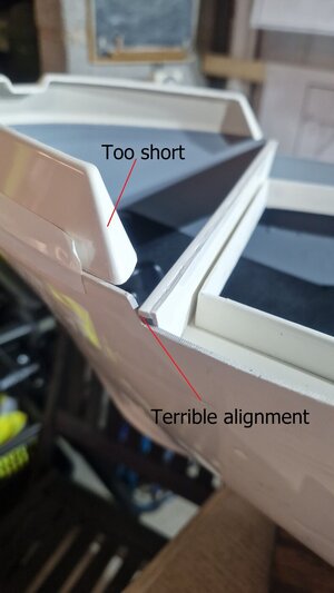
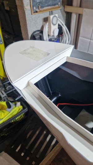
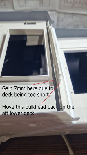
The decks (especially the foredeck) fit absolutely awfully. Massive gaps and the centre deck section appears to be 7mm too short.
The moulded bow section also appears to be far too short.
I found someone else's build pictures and it looks like they had the same issue, as they have stitched 10mm onto the moulded bow section to make it long enough.
I will have to do the same.
So, the only way I can make this fit (and I have gone over this in depth to make sure there are no obvious errors), is to take the midships bulkhead off and extend the rear deck by 7mm. Annoying, but hey ho. If I adjust anything anywhere else, it will mess up the superstructure install.
You can see the gap in the deck where I had to move it forward.
So, after some shaping and swearing, I have got it much nearer a reasonable fit. Still a way off, but certainly better than it was.
I am fairly sure this is an early kit. Some of the parts are timber (and so badly warped they are unusable). I have finally found a decent build guide with images and this shows that a lot of pieces have been replaced. Namely the timber parts.
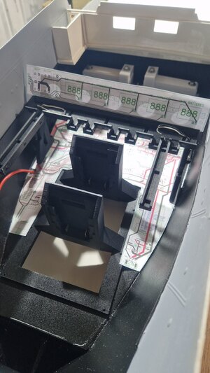
Did a test with the electronics. All seems OK there, so I will get the PCBs made.
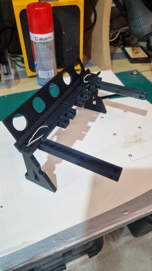
I moved the LED voltmeters up to a more visible position on the 3d-printed cable frame (above and behind the batteries).
Still waiting for my Vape heaters to arrive so that I can design and install the smoke generators.
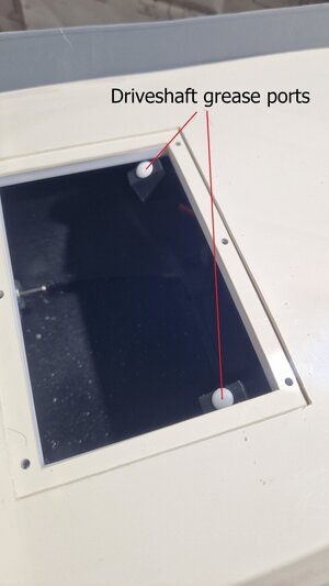
Also extended the driveshaft grease ports into the rear deck opening.
The front deck has two openings. One large one above the batteries and a smaller one further aft (meant for accessing the towing mechanism).
I am going to look and enlarging all of that access if possible. I have already had to re-enforce all the mouldings that came with the kit as they were very flimsy.
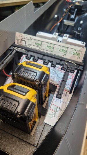
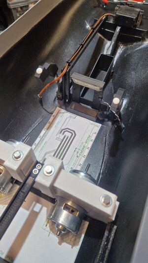
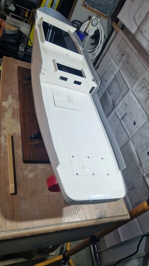
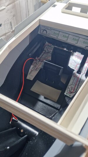


Great set up on your drive line and battery power supply. I know your tug hull will be able to handle the extra displacement of those batteries for long duration runs. Love your project and am following it closely.
Jim
Jim
- Joined
- Jun 20, 2024
- Messages
- 26
- Points
- 48

Well I am doing what I always do and making it far more involved than it needs to be!
The main PCB has been edited a few times so far. I found an old Robersonics WAV player in my workshop which is superior to the MP3 player module I was going to use.
It's a bigger footprint, but that is fine.
The advantage to that sound module is you can overlay up to 16 stereo tracks at the same time and alter the pitch of the track. This works really well for the looped engine sound effects. I built a full scale Starship once as a prop, and the engines could be throttled up and down as required.
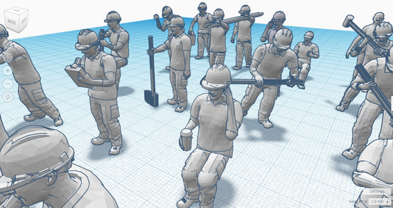
I was looking for some 1:50 scale figures for the deck. HOW MUCH!! Madly expensive.
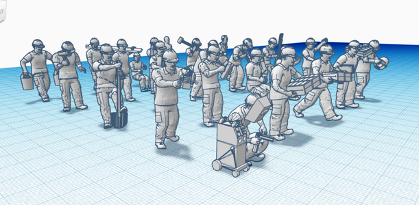
So I searched on Thingyverse and found some N-Scale construction workers that I can 3d print. I imported them into CAD at 300% scale increase and I think they will work fine as 'crew'
I will tweak about with them, add some life jackets etc and try printing some in fine detail.


- Joined
- Jun 20, 2024
- Messages
- 26
- Points
- 48

Not had much time this past week or so, but here we are...
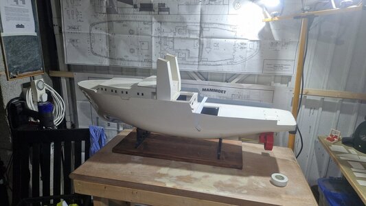
Build up the lower part of the superstructure, just so that I can get the footprint. Yet more massive gaps to fill, but I will deal with all that later this week.
I am throwing together the main framework and structures and then going back for a full fill 'n' prime later.
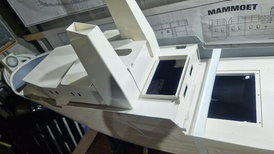
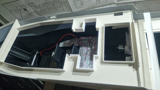
I needed the footprint on the superstructure, as I have cut out a lot more front deck and then 3d printed new supports frames to give much better access.
I also 3d printed some 'I beams' to run underneath the deck for a bit more strength. PETG so strong but very light.
I put the shells of the funnels together and then removed most of the deck from underneath them. They normally get fitted to the deck, but I am fitting them to the superstructure and the whole thing can lift off as one.
This funnel floor removal gives me room for a pair of push-fit connectors for the working funnel smoke.
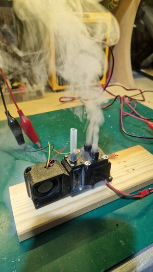
I designed and built a dual outlet smoke generator using an 0.6ohm mesh Vape coil. Easy to change the coil if I need to (hence the extra deck access).
This smoke generators lives in the Pump room on the Pump room PCB.
The fan for the smoke generator is PWM controlled and so I can vary the smoke with the throttle. There is also an optical sensor in the output chamber so that if the fan is running, but the smoke stops, it turns off the heater coil so that it doesn't burn out.
I am quite impressed by the amount of smoke this little generator pushed out. Runs on fragrance free, dirt cheap, vegetable oil.
It leaks at the moment from the screwed on pipe outlets, as I have not yet sealed those on. Should not leak smoke once sealed up.
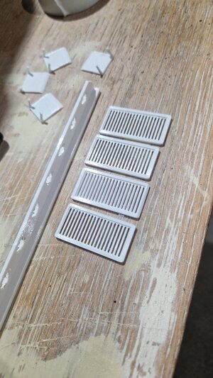
3d printed some detailed grilles for the funnels. I will cut them out behind to allow air down into the pump room.
Hopefully you can view the smoke generator video... I ramped the fan down and then back up to about 60%.


- Joined
- Jun 20, 2024
- Messages
- 26
- Points
- 48

...and so I plod on.
Started looking into all the winches and motors. The kit comes with some (rather ropey) looking winch frame arrangements that use the plastic as bearings in some cases. You then add some weird looking geared motors that were obviously available way back then.
I dug around the workshop and found various geared motors.
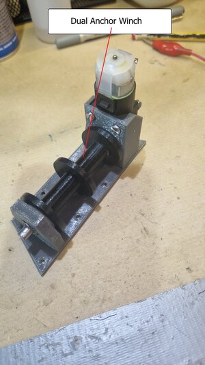
First, the anchor winch. The kit only has one working anchor. I have 3d printed my own dual anchor drum and both anchors will work.
The rear of the superstructure houses a very badly explained arrangement for a towing winch. I still have no idea how the heck it is supposed to actually work.
So, I have made my own.
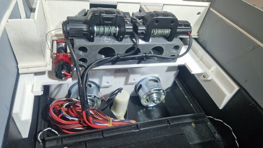
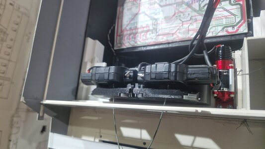
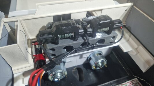
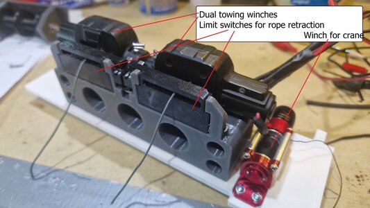
I searched about in the workshop and found 3x RC Off-road car scale winches. Used them for a special effect on a stage years ago,
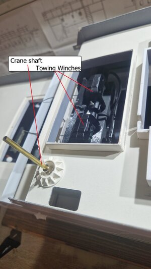
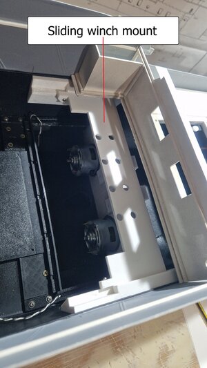
The kit had one working towing winch, but I have installed a pair (the boat does have two). These winches work far nicer. I can individually control them.
They are mounted on a sliding 3d printed platform whose runners are heavily glued to the main hull (for towing strength). The kit had a wooden shelf, but it's all warped and awful.
The winch mount also has a pair of microswitch triggering rope limit panels. The rope goes through them and they stop the motors when fully retracted.
I will also add a sensor (yet to decide what) to stop the motors at full cable payout. The rollers are bright metal, so I could achieve this with either a set of contact that make when all the rope is off the drum, or an optical sensor that reflects off the shiny metal drum.
Or, the processor could simply time them. Worst case, the winch will just start rewinding the other way.
Also on this platform is the little red RC winch that will be for the working crane.
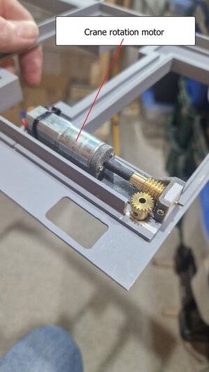
Next was a rotation motor for the crane. Made a little mount for the worm gear. Used some Delrin for the end bearing block (no load really on this).
Also added a bearing into the deck so that it rotates nicely.
The 3d printer is running now to create a servo mount that goes below this motor and adds the lift/fall action to the crane boom.
The kit uses yet another winch for that, but I think a small 10g servo will work better.
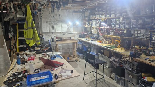
All I can say is thank God for 3d printing.... As you can see, it's kinda taken over a large part of my workshop!
Also been writing the code for the receiver and transmitter. I have added a digital compass module (£3.99). This now transmits the heading of the boat back to the controller.
Don't need that.... but why not!


Fantastic operational detail you are adding to this project. I am really enjoying following your progress.
Jim
Jim
- Joined
- Jun 20, 2024
- Messages
- 26
- Points
- 48

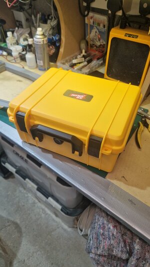
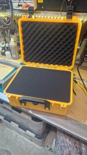
My £8.42 delivered from China controller enclosure arrived today. How do they do it for the money. It's just a waterproof enclosure, and I will add a neck strap to it.
Its not your standard controller enclosure. I did 3d design a transmitter housing (similar to my Robbe F14 controller), but I actually like the idea of this controller being a bit industrial and different.
I'll laser cut a lid and base panel in some black Acrylic and fit all my controls to that.
I will probably put some kind of screen in the lid, and that can have a readout of all the boats information. E.G. Heading, speed, battery level etc


- Joined
- Jun 20, 2024
- Messages
- 26
- Points
- 48

Just raided the shopping mall called China.
7" Nextion touchscreen will go in the lid of that controller. Used these screens before and they are super sexy. Probably the most expensive bit I have bought (£59) but well worth it.
This now means I can have a live information screen showing motor RPMs, heading, speed, battery level etc
It's also nice because being a touchscreen, I can have a lot of the functions as touch buttons. I can make a 'Crane operations' page, or a 'lighting' page for instance.
Added an MPRLS pressure sensor to the PCB. Found it in my workshop of many things. This means I can add a tiny Pitot tube to the hull and this will report back the forward speed.
Also grabbed some small RC car floodlights. Not technically the correct scale, but they should do fine. Floodlights after all are not going to throw the scale out.
Also grabbed a rotating yellow beacon to operate while the crane is live. I have a master on/off for the crane and this beacon will operate while the crane is live.
I will also add a warning siren for a few seconds when the crane is first turned on. Might have a switchable option for a constant warning beeper while the crane actually moves (which is why the touchscreen will work well).
I have decided to make the helm/bridge a bit more detailed as well. I already plan to have a tiny scale working radar screen. I will expand off that.
Finally, looking into the options for wireless cameras. Would be outstanding to have a camera in the wheelhouse.
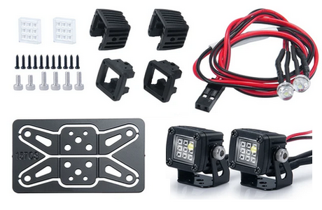
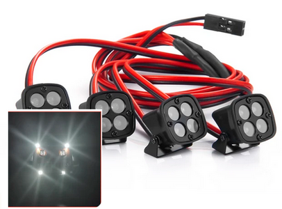
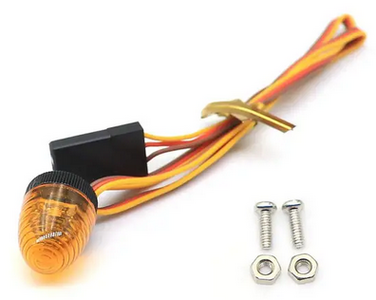
I will add that the rotating beacon is the wrong scale, but I have had a look and I can 'rescale' it to be nearer 1:50.
7" Nextion touchscreen will go in the lid of that controller. Used these screens before and they are super sexy. Probably the most expensive bit I have bought (£59) but well worth it.
This now means I can have a live information screen showing motor RPMs, heading, speed, battery level etc
It's also nice because being a touchscreen, I can have a lot of the functions as touch buttons. I can make a 'Crane operations' page, or a 'lighting' page for instance.
Added an MPRLS pressure sensor to the PCB. Found it in my workshop of many things. This means I can add a tiny Pitot tube to the hull and this will report back the forward speed.
Also grabbed some small RC car floodlights. Not technically the correct scale, but they should do fine. Floodlights after all are not going to throw the scale out.
Also grabbed a rotating yellow beacon to operate while the crane is live. I have a master on/off for the crane and this beacon will operate while the crane is live.
I will also add a warning siren for a few seconds when the crane is first turned on. Might have a switchable option for a constant warning beeper while the crane actually moves (which is why the touchscreen will work well).
I have decided to make the helm/bridge a bit more detailed as well. I already plan to have a tiny scale working radar screen. I will expand off that.
Finally, looking into the options for wireless cameras. Would be outstanding to have a camera in the wheelhouse.


I will add that the rotating beacon is the wrong scale, but I have had a look and I can 'rescale' it to be nearer 1:50.
Last edited:
- Joined
- Jun 20, 2024
- Messages
- 26
- Points
- 48

Well, some things work and some don't.
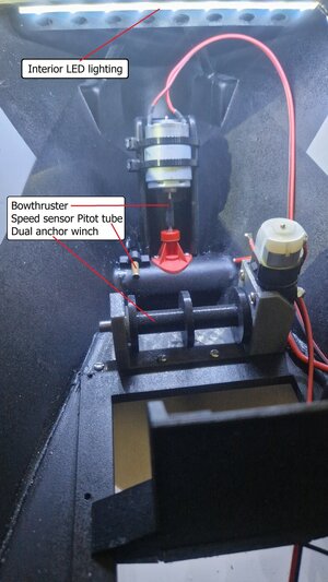
Got the supplied bow thruster installed and (with some improvements), it works fine.
Also installed the Pitot tube on the bow for the pressure sensor that reports back the speed through the water.
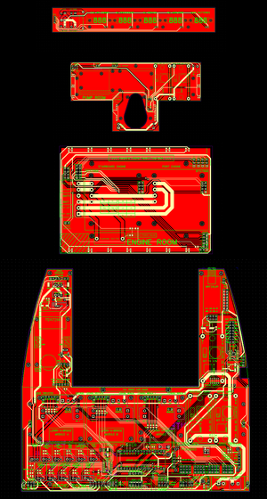
All the PCBs are ordered, so they should be here in the next 10 days.
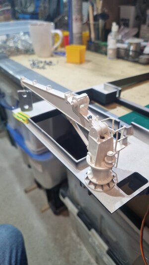
So.... this &*%# crane.
I knew it wasn't well designed. I have watched several videos of other peoples cranes operating and its jerky and very unrealistic.
The gearbox that drives the rotation is sweet. That works very well and is lovely and smooth.
The problem is the boom lift. The plans show a (horrible) arrangement of another winch that pulls a 0.3mm steel wire down a 1mm tube that lives inside the 6mm tube that rotates the crane.
This thin steel wire then attaches to the top of the crane boom. This is the design issue. Due to the pivot point for the boom being so close to the end, the wire only needs to pull 5mm or so to raise the boom up to it's full height.
This also requires some considerable pulling, as the you are lifting the entire boom (not to mention anything you pick up) with an incredibly short amount of leverage.
I abandoned the winch they suggest, as I don't have room for yet another winch, and an entire winch for 5mm of cable pull seemed mad.
So, I tried a small 10g servo. It does work, but its super jerky and really doesn't have the ability to lift much. Mainly because the cable stretches under any load, and once you are over the initial weight of the boom lifting, it suddenly gets lighter and springs up.
Plus, with the winch rope also going up the centre of the crane tube, its all a bit of a horror show to install.
Rethink time.
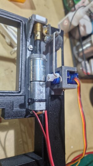
I have a very small geared motor. I could possibly add this to the actual crane to control the lifting mechanism. I am not worried about the aesthetics of the crane, I don't mind a bit of free licence if it makes it work better.
This would need power, so I might have to add a set of brushes to the rotary plate to allow that to work. Not ideal.
The crane only actually rotates 270 degrees. You could probably just disguise the motor cables as hydraulic hoses.
The other option is to leave the servo under the deck, and try lifting the boom with a cam instead. A full sweep of a servo wit h a cam would significantly increase it's lifting ability.
Hmm


- Joined
- Jun 20, 2024
- Messages
- 26
- Points
- 48

Just found some Nitinol wire in the workshop.
I am thinking either Nitinol wire actuator underneath the crane (where the current fake hydraulic cylinder is) or Nitinol pull line
I am thinking either Nitinol wire actuator underneath the crane (where the current fake hydraulic cylinder is) or Nitinol pull line
- Joined
- Jun 20, 2024
- Messages
- 26
- Points
- 48

The Nitinol wire actual works quite well. I am going to set it up better and that might be the way forward for the crane boom lift.
For those that don't know.... Nitinol wire returns to its original set shape (which you set by heating to red with a blowtorch), when you apply a current.
So, you can design actuators, springs etc and use that as a very small actuator (but it's incredibly strong).
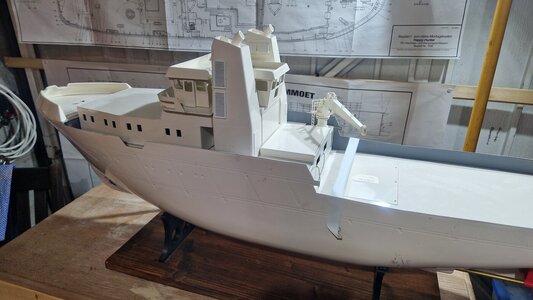
I had a day yesterday of TEDIOUS window cutting for the superstructure. Threw all those main components together so that I could plan the top half of the build. LOTS of filling and fine work to do on those to make them primer ready.
Templated the superstructure so that I could look at some interior detail. The original kit just has a big holes for cables to drop through the superstructure.
I am putting in much neater wiring than that in a duct riser that goes from the engine room upwards.
So, that big hole in all the floors will become a 3d printed stairwell.
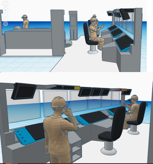
The superstructure templates are now in Tinkercad (I have Fusion 360, but Tinkercad is so much quicker for these kinds of simple builds).
This means I can start designing the bridge interior that will all be 3d printed.
The design of the bridge interior here is far from finished. Just starting to work out the layout (I can't find any reference images of the Happy Hunter bridge).
Those 1:50 figures I created from the free Thingyverse download are proving handy (as is the scale conversion website I found).
I will get vinyl graphics for all of the control panels, and there will be working OLED screens on the consoles showing gauges and a sweeping radar (oh, and lots of lovely fibre-optic tiny lights!)
The roof of the superstructure should be glued on, but I am making it all magnetic fit.


Last edited:
- Joined
- Jun 20, 2024
- Messages
- 26
- Points
- 48

Not had much time this week.
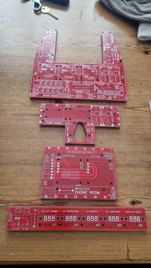
PCBs have turned up. Looking rather damn fine. I'll try to get those populated over the weekend.
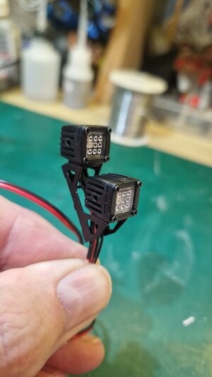
Also some RC off-road spotlights have turned up from Aliexpress. They work very well and cost next to nothing. Will certainly get some more of those.
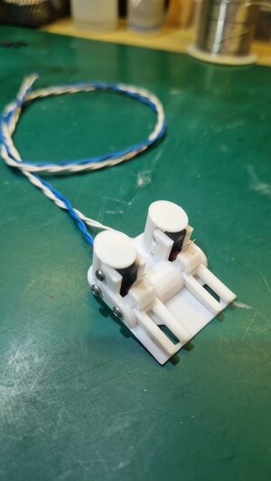
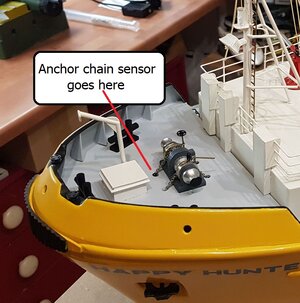
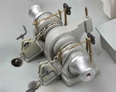
Designed a small foredeck anchor module that the chains run through before going over the fake winch mechanism. This module houses a couple of slit levers connected to micro-switches that will detect a small ball attached to the anchor chains. These sensors will stop the winches.
Pic attached of someone else's finished boat just for reference.


- Joined
- Jun 20, 2024
- Messages
- 26
- Points
- 48

Got most of the PCBs assembled.
The main radio room PCB (the biggest one) still has some parts missing which have not arrived.
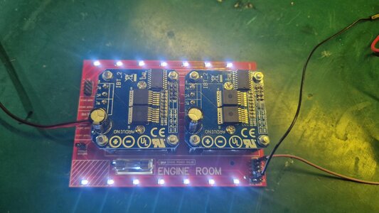
The picture with the voltmeter bridge temp connected is the radio room PCB
All gone together (so far), quite nicely.
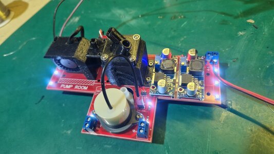
The pump room (with the little bilge pump in the middle) has the smoke generator core removed as I am slightly re-designing that piece.
I do like the white lighting along the PCB edges of the pump and engine room PCBs. They are on their own circuit and come on with the LEDs under the voltmeter frame that crosses over the Radio room PCB. That frame also provides a wiring route.
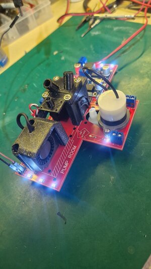
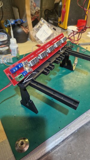
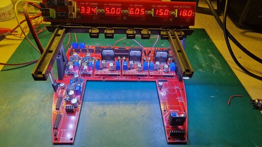
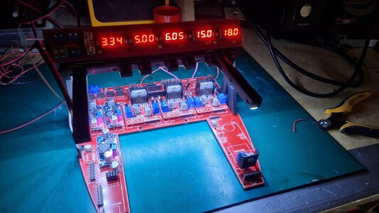
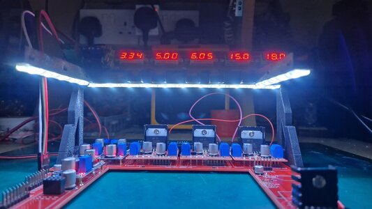


This is without a doubt the most technically operational RC boat I've ever encountered. Great work.
Jim
Jim
- Joined
- Jun 20, 2024
- Messages
- 26
- Points
- 48

Ha... thanks.
It does have lots of protection incorporated, as it will all no doubt get wet.
I tested the boards powered this afternoon and dropped them into a tub of water. The protection worked well and the entire system immediately shut down except for the bilge pump.
Shook the PCBs dry and it all fired back up.
Long way to go yet!
- Joined
- Jun 20, 2024
- Messages
- 26
- Points
- 48

The &*#% crane is a nightmare. Very close to binning it entirely and making my own from scratch.
Finally got it kinda working. Currently, the motors are just thrown across some power supplies, so no fine control.
They will eventually work off a H-Bridge PWM module, so that will make the motors run far nicer and the slower speeds will be much smoother.
The crane boom lift is now on a servo. I managed to alter the gearing so it lifts using a servo to give it much more power.
This is temp connected here to an old RC controller, so it's a bit jumpy. When the processor is controlling it, I can smooth that out with much smaller servo steps.
The winch sound awful because it's running on 2v here and it's a 6v motor. When it's running on 6v PWM, it sounds far nicer.
Plus, there are SFX that play while the crane is operating.
Still not convinced yet however that I won't totally rebuild that crane.

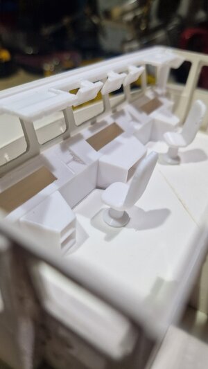
The wheelhouse internals have been 3d printed. Just lots of details to add now.
Drawn out all the control panels, charts, maps, radars etc in Photoshop and I will get those made as fine detail vinyl stickers.
Then it's lots of fine painting/airbrushing as well.
Added a stairwell to the hole that is usually used for wiring.
The gaps in the front control panel (3x long slots) will be actual working OLED screens with rotating radars, depth graphs etc.
I am trying to get all the main parts build before I spend a whole pile of time filing, sanding and painting. I need to ensure I know how it's all going to go together.
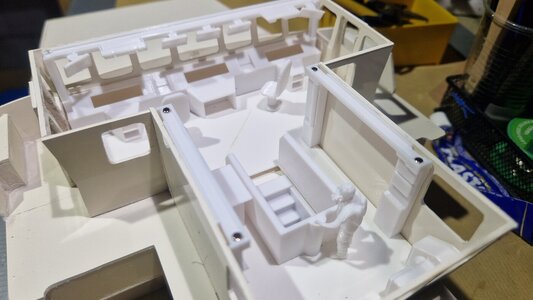
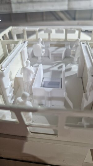
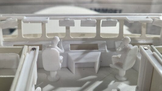
Finally got it kinda working. Currently, the motors are just thrown across some power supplies, so no fine control.
They will eventually work off a H-Bridge PWM module, so that will make the motors run far nicer and the slower speeds will be much smoother.
The crane boom lift is now on a servo. I managed to alter the gearing so it lifts using a servo to give it much more power.
This is temp connected here to an old RC controller, so it's a bit jumpy. When the processor is controlling it, I can smooth that out with much smaller servo steps.
The winch sound awful because it's running on 2v here and it's a 6v motor. When it's running on 6v PWM, it sounds far nicer.
Plus, there are SFX that play while the crane is operating.
Still not convinced yet however that I won't totally rebuild that crane.
The wheelhouse internals have been 3d printed. Just lots of details to add now.
Drawn out all the control panels, charts, maps, radars etc in Photoshop and I will get those made as fine detail vinyl stickers.
Then it's lots of fine painting/airbrushing as well.
Added a stairwell to the hole that is usually used for wiring.
The gaps in the front control panel (3x long slots) will be actual working OLED screens with rotating radars, depth graphs etc.
I am trying to get all the main parts build before I spend a whole pile of time filing, sanding and painting. I need to ensure I know how it's all going to go together.


