HM Sloop Fly, 1776 - scale 1/36 by own reconstruction and the books from David Antscherl

I have David and Greg's first 3 volumes and looking foward to your build. I like that you will be using the cnc mill for cutting and shaping the parts for the build, I hope that you will spend more time showing the processes using the mill and setup as you progress.
 
@Uwek, @The learner
Thanks for your interest in my project.

The learner
I am currently a long way from the knowledge and possibilities that some Chinese artists or @SZKUTNIK have already demonstrated here on board. As long as my 3D CAD knowledge is not yet sufficient, I will continue to use my CNC in 2.5D. I will be happy to show you my approach.
 
Witaj
Piękna praca . Z przyjemnością będę ja oglądał . Pozdrawiam Mirek

Hello
Great job . I will be happy to watch it. Regards, Mirek
 
Last edited by a moderator:
I am currently milling the components for the backbone of my ship sloop.
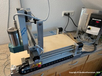
The photo shows my small CNC. Not in the picture is the control unit for the milling machine.
Fly-006.jpg

I am using a 16mm birch multiplex board from the DIY store as a support plate. Before starting the milling work, the working area of the milling machine must be milled flat to ensure that the boards are aligned parallel to the milling machine later on. The holes that can be seen are used to attach the boards to the support plate. I chose this arrangement based on my experience of milling the first components for my Alert last year.
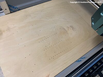
Fly-007.jpg

Milling from two sides is a particular challenge. On the keel, for example, the rabbet and chocks are milled from both sides. In addition, each milling cutter only has a limited milling depth (with a diameter of 0.5mm, for example, it is only 3mm). In order to mill a thicker board, it is necessary to mill from both sides. A forced centering is essential for these milling operations.

The first step is to prepare the board for the components.
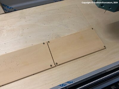
Fly-008.jpg

I use an MDF board for the forced centering, as the material is available cheaply at DIY stores. A precisely fitting recess is milled into this for the prepared board.
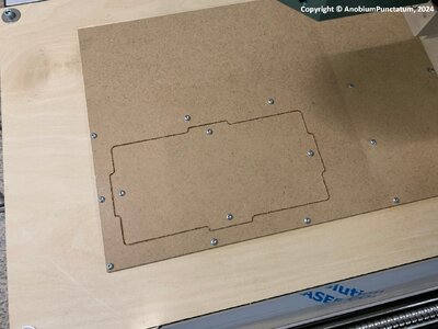
Fly-009.jpg

The board is then screwed into the recess and the back is milled. Now the importance of the holes in the support plate will probably become clear. The next picture shows the board after milling the required recesses.
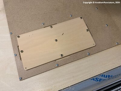
Fly-010.jpg

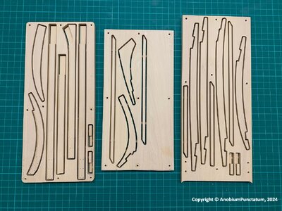
The board is then turned over and the cut-outs milled first. Finally, the components are "cut out".
The last two pictures show the components of the Knee of the Head from the front and the back with the retaining bars.
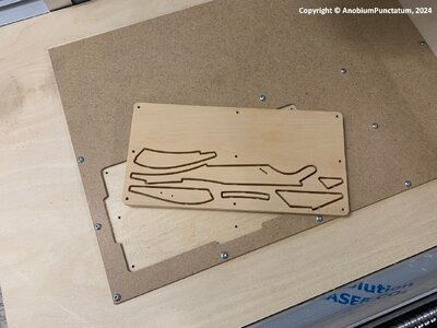
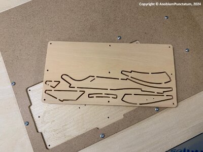
Fly-011.jpg

Fly-012.jpg

Over the next few weeks, all the components for the backbone of HM Sloop Fly will be milled before assembly begins.
 
Hello Christian,
Fascinating topic and great explanation from you. I have great respect for your work, including your own designs. Thank you for explaining and showing. Your construction report is very exciting and I look forward to every further installment.

Hallo Christian,
Faszinierendes Thema und tolle Erläuterung vin Dir dazu. Ich habe großen Respekt vor deiner Arbeit dazu auch deiner eigenen Konstruktionen. Danke fürs Erläutern und Zeigen. Dein Baubericht ist sehr spannend und ich freue mich auf jede weitere Fortsetzung dazu.
 
so much preparation works - but the result is looking very promising
For me it is like "spanische Dörfer" but good to know, who has such knowledge
 
Hello Christian,
If I come to your area again, you must show me this live. Great report!


Hallo Christian,
Falls ich nochmals in deine Gegend komme, mußt mir das mal in Live zeigen. Toller Bericht!
 
Milling the components takes some time. This weekend I milled all 12'' of the backbone (keel, false keel, keelson).

Fly-013.jpg

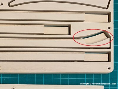
Despite the preparation and the choice of boxwood, wood has its pitfalls. On the marked component (transition to the lower stem), a piece of the prepared sponge and the edge burst off. It is difficult to find the cause of such errors. Perhaps the milling cutter was no longer sharp enough. Or the position of the holding points was wrong for the fragile component.

Fly-014.jpg

I will mill the part next weekend again.
 
Before I can continue with the components for the keel, I have to build the two deadwoods. I need these to be able to mill the corresponding recesses for the fittings.

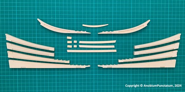
For the construction I used the technique I described in the building report on the Alert. I made the fittings, which will later be embedded in the keel, separately to increase stability. The picture show the different parts of both deadwoods.

Fly-015.jpg
 
Witaj
Piękna praca Christianie maszyny są niesamowite ale najważniejsza jest umiejętność ich obsługi pięknie te części wyglądają , powstaje piękny model oglądam z przyjemnością . Pozdrawiam Mirek
 
Before I can continue with the components for the keel, I have to build the two deadwoods. I need these to be able to mill the corresponding recesses for the fittings.

For the construction I used the technique I described in the building report on the Alert. I made the fittings, which will later be embedded in the keel, separately to increase stability. The picture show the different parts of both deadwoods.

View attachment 434075
Wow, masterfully done.
 
Back
Top