- Joined
- Oct 23, 2018
- Messages
- 886
- Points
- 403

 |
As a way to introduce our brass coins to the community, we will raffle off a free coin during the month of August. Follow link ABOVE for instructions for entering. |
 |
 |
The beloved Ships in Scale Magazine is back and charting a new course for 2026! Discover new skills, new techniques, and new inspirations in every issue. NOTE THAT OUR FIRST ISSUE WILL BE JAN/FEB 2026 |
 |


Your preparations are well thought out. And the result is accordingly, Christian. A pleasure for the eyes.Before I continue with the my build log, let's take a look back to some preparations which I executed in the last few months:
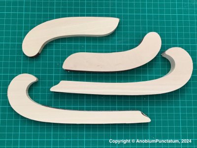
After milling the components, they have to be removed from the boards. As the boards are subjected to mechanical stress during milling, the holding bars are significantly larger than with laser-cut components. To do this, I use a pin block into which a fretsaw blade is clamped. The remains of the bars are then sanded away. I have milled some “sanding blocks” from lime wood for this purpose. I stuck 120-grit sandpaper to these with double-sided adhesive tape.
View attachment 488875
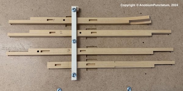
The last preparatory step was to cut some recesses in the various components for fitting and drilling holes for later mounting the model on its stand.
View attachment 488876
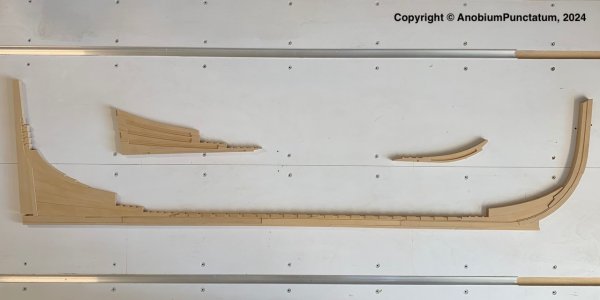
The last picture shows all the prepared components of the backbone of my sloop.
View attachment 488877


Good choice, the Mac is great. You'll have to get used to it a bit, a few keys are different, but after a few uses you'll get the hang of it.Thanks Tobias,
You need a little bit of patience until I can show the first frames. I have a new computer for the design (now a Mac). My old Windows computer will replace my really old PC for the CNC. I am afraid that the update need more time than I expect now.
Thanks Tobias,
You need a little bit of patience until I can show the first frames. I have a new computer for the design (now a Mac). My old Windows computer will replace my really old PC for the CNC. I am afraid that the update need more time than I expect now.
I fully agree with Tobias. For design and photography a iMac is ideal to work with. I am working with them for many years.Good choice, the Mac is great. You'll have to get used to it a bit, a few keys are different, but after a few uses you'll get the hang of it.

Neatly done work Christian! It is hard to tell from the photos, but does the keel breadth taper at the area of the boxing joint and stern post as described in TFFM or will you be doing this after the stern post and stem are assembled to the keel?

Hello Christian,Eight years ago, I reconstructed the line plan of the Fly based on the original plans and drew a disposition of frames plan adapted to my model. Inspired by the build logs from dockattner and Giampy65, I started to check and revise my old drawingss at the beginning of November last year. When editing in CAD, I set the scale to 1 inch = 1 drawing unit.
I was able to complete this revision at the end of 2023.
As an example, I show you the disposition of frames plan and my control drawing for the derived frames.
View attachment 418314
View attachment 418317
I then drew the backbone of the ship. As the arrangement of the components has not been handed down, I used the information provided by David Antscherl as a guide.
View attachment 418316
The components are now derived from the last drawing.

I've seen this and adopted this on my reconstruction.- the square frame Laft is not vertical frame. the angle Laft (toptimber) with vertical is 0.68°.
- the square frame Gaft is not vertical frame. the angle Gaft (toptimber) with vertical is 0.73°.
- the square frame Caft is not vertical frame. the angle Caft (toptimber) with vertical is 0.86°.
I agre with you. It is only right way to use the source draught, to preserve authenticity as much as possible.Hello Peter,
I have used ZAZ4691 for my frame design and tried to follow it as far as possible. There are some inconsistencies with the as-built drawing of the chosen sloop Fly. I decided to use the as-built drawing ZAZ4667 as main source for my reconstruction.
I've seen this and adopted this on my reconstruction.
For the can't frames I used the positions and angles given in the as-built drawing of my sloop.
I own the books from David and Greg, but if I have primary sources I will use this for my work.
Your research is truly impressive! As-builts are always the best choice if looking for accuracy of how the ship was built, and comparing the 1773 framing disposition with the later profile plan had to take a good amount of work to find the differences. KudosI have used ZAZ4691 for my frame design and tried to follow it as far as possible. There are some inconsistencies with the as-built drawing of the chosen sloop Fly. I decided to use the as-built drawing ZAZ4667 as main source for my reconstruction.
