Very nice result, crisp edges and it fits perfectly. Great job, happy new year to you too.
-

Win a Free Custom Engraved Brass Coin!!!
As a way to introduce our brass coins to the community, we will raffle off a free coin during the month of August. Follow link ABOVE for instructions for entering.
-

PRE-ORDER SHIPS IN SCALE TODAY!
The beloved Ships in Scale Magazine is back and charting a new course for 2026!
Discover new skills, new techniques, and new inspirations in every issue.
NOTE THAT OUR FIRST ISSUE WILL BE JAN/FEB 2026
You are using an out of date browser. It may not display this or other websites correctly.
You should upgrade or use an alternative browser.
You should upgrade or use an alternative browser.
HM Sloop Fly, 1776 - scale 1/36 by own reconstruction and the books from David Antscherl
- Thread starter AnobiumPunctatum
- Start date
- Watchers 35
-
- Tags
- 1776 fly sloop swan class
- Joined
- Oct 23, 2018
- Messages
- 886
- Points
- 403

@All
Thank you very much for your nice words,
@dockattner
As you can see, they can. Some years ago we had trouble with the German copyright law in a forum, which does not exist anymore. To avoid this, we started to add the © information in the pictures.
@BradNSW
Not "or"! ... and to start the New Year. Today I will continue with the fore deadwood and the rising wood. I am on holiday and have time to work on my model.
Thank you very much for your nice words,
@dockattner
Question: can photo rights really be assigned to beetle larvae ?
As you can see, they can. Some years ago we had trouble with the German copyright law in a forum, which does not exist anymore. To avoid this, we started to add the © information in the pictures.
@BradNSW
[...] Laying the keel and deadwood rise...a great way to close out the year (or start the next)!
Not "or"! ... and to start the New Year. Today I will continue with the fore deadwood and the rising wood. I am on holiday and have time to work on my model.
Last edited:
- Joined
- Oct 23, 2018
- Messages
- 886
- Points
- 403

After the installment of the deadwood, it was necessary to workout the rabbet at this difficult part. As David Antscherl in his books show, there is a transition in the rabbet which takes the shape of the deadwood. With really small pieces of sandpaper on different wooden sticks I sanded the transition in deadwood and also in the rabbet.
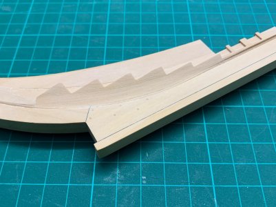
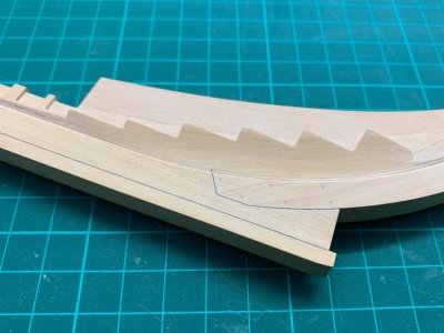
After finishing this task the two pieces of the rising wood were installed. I added 2 nuts to screw the model later on his stand. Perhaps the middle nut is not necessary, but I did not make any decision for the stand until now.
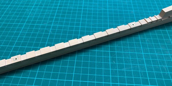
Then the rabbet was also worked out in this part. What you can really good see in the following macro from the starboard side is the small inaccuracy which happened during glueing the parts together. This I could not avoid but I do not think that it will make any problems in the future.
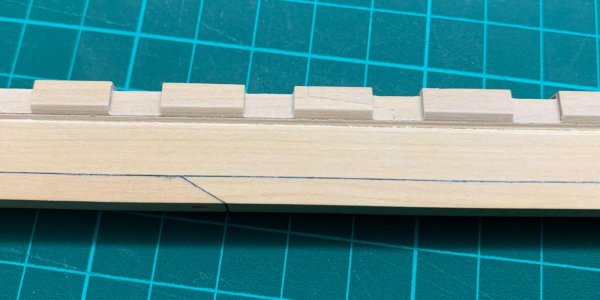
Also with CNC prepared parts there is a lot of manual work which makes me also a lot of fund.
Tomorrow I will start with stern section. The after deadwood and stern parts are in my opinion the much complicated parts of the whole backbone. I checked today if everything fits together and I am really happy that it looks fine and my given tolerances are enough.
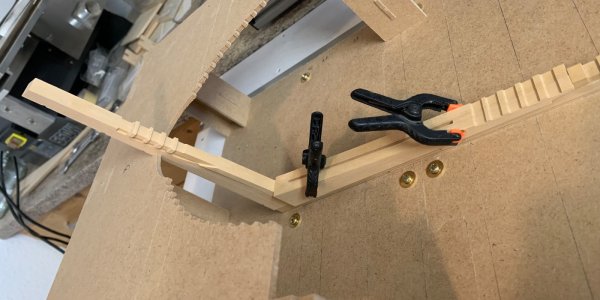


After finishing this task the two pieces of the rising wood were installed. I added 2 nuts to screw the model later on his stand. Perhaps the middle nut is not necessary, but I did not make any decision for the stand until now.

Then the rabbet was also worked out in this part. What you can really good see in the following macro from the starboard side is the small inaccuracy which happened during glueing the parts together. This I could not avoid but I do not think that it will make any problems in the future.

Also with CNC prepared parts there is a lot of manual work which makes me also a lot of fund.
Tomorrow I will start with stern section. The after deadwood and stern parts are in my opinion the much complicated parts of the whole backbone. I checked today if everything fits together and I am really happy that it looks fine and my given tolerances are enough.

After a lot of pre-work now you got your pace, Christian. It’s looking very nice.After the installment of the deadwood, it was necessary to workout the rabbet at this difficult part. As David Antscherl in his books show, there is a transition in the rabbet which takes the shape of the deadwood. With really small pieces of sandpaper on different wooden sticks I sanded the transition in deadwood and also in the rabbet.
View attachment 492802 View attachment 492803
After finishing this task the two pieces of the rising wood were installed. I added 2 nuts to screw the model later on his stand. Perhaps the middle nut is not necessary, but I did not make any decision for the stand until now.
View attachment 492804
Then the rabbet was also worked out in this part. What you can really good see in the following macro from the starboard side is the small inaccuracy which happened during glueing the parts together. This I could not avoid but I do not think that it will make any problems in the future.
View attachment 492805
Also with CNC prepared parts there is a lot of manual work which makes me also a lot of fund.
Tomorrow I will start with stern section. The after deadwood and stern parts are in my opinion the much complicated parts of the whole backbone. I checked today if everything fits together and I am really happy that it looks fine and my given tolerances are enough.
View attachment 492806
Regards, Peter
Very nice work on the rabbet, Christian. The keel looks wide but now I see that you are building at 1:36. Inspiring.
- Joined
- Oct 23, 2018
- Messages
- 886
- Points
- 403

@all
Thanks for your Likes
@Peter Voogt
I am on holiday, from the begin of next week I am back on my job, so much less time for the hobby. After finishing the backbone I have to prepare all the boards which I need for the frames. I think the second year of my build is mostly building frames.
@dockattner
Thank you very much my friend. I thought a longer time, which scale I should use for my build. 1/48, 1/32, in the end it is 1/36 or 1in/3ft The size is (without rigging ) really good to manage in our apartment and the scale is for me simpler to work with than 1/48.
Thanks for your Likes
@Peter Voogt
After a lot of pre-work now you got your pace, Christian. It’s looking very nice.
I am on holiday, from the begin of next week I am back on my job, so much less time for the hobby. After finishing the backbone I have to prepare all the boards which I need for the frames. I think the second year of my build is mostly building frames.
@dockattner
The keel looks wide but now I see that you are building at 1:36. Inspiring.
Thank you very much my friend. I thought a longer time, which scale I should use for my build. 1/48, 1/32, in the end it is 1/36 or 1in/3ft The size is (without rigging ) really good to manage in our apartment and the scale is for me simpler to work with than 1/48.
…… then we can shake hands. But after that new fun started.I think the second year of my build is mostly building frames.
Regards, Peter
This is true. Of course working at 1:36 allows the addition of even finer details which turns the simpler into 'just as hard.' But for sure timbering is easier at the larger scale.the scale is for me simpler to work with than 1/48
I may be a bit late, but i just received a transcribed copy of the contract for a Swan Class vessel yesterday. The following are the dimensions for the Swan Class vessel Hornet 1775 from the contract.
Allan
Keel. The keel to be Elme not more than four pieces 12ins sq at midships, sided afore 10 ½ ins & at the after part of the rabbit of the post 8 ½ ins. The scarphs 3ft 6ins long tabled one into the other laid with Tar & haire & bolted with 6 bolts of 7/8 in diameter. The lips of ye scarphs not to be more in thickness than 3 5/8ins.
False Keel. The false keel to be in one thickness of 5ins to make the main & false keels together 14ins below the rabbit, to give scarph to the scarphs of the main keel to be laid with Tar & hair & sufficiently fastened with nails & Staples.
Stem. The stem not to be more than 2 pieces of good sound Oak quite free from defects of any kind, sided at the head athwartship 14ins which is to be diminished at the lower side of the lower Cheek to 12ins which bigness is to be continued down as low as is consistent with its tapering in with the bigness of the keel at the fore end, to be moulded at the head & lower end the same as the keel, the scarphs to be 3ft 4ins long tabled one in the other laid with Tar & hair & bolted with 6 boltes of 7/8 ins diameter. 2 of the middle bolts to go through the false Stem or Apron & well clenched thereon. The lips of the scarphs not to be more than 3 5/8ins thick.
Apron. The False Stem or Apron to be 6 ½ ins thick & 18 broad to overlaunch the Scarphs of the stem above & below, & the scarphs to be 12ins long.
- Joined
- Oct 23, 2018
- Messages
- 886
- Points
- 403

Hi Allan,
thank you for the information. I have used the as built drawing of Fly for my reconstruction. A lot of the given values are really similar. Do you have more informations, especially from the beams? There are a lot of differences between Repository, Steel and the as built drawings. It would be nice if I can verify the values of the drawing with another source,
thank you for the information. I have used the as built drawing of Fly for my reconstruction. A lot of the given values are really similar. Do you have more informations, especially from the beams? There are a lot of differences between Repository, Steel and the as built drawings. It would be nice if I can verify the values of the drawing with another source,
HI Christian
I am not at liberty to share the contract as a whole but I would be happy to post the dimensions of the beams if you wish. Like you as-built drawings are always the best in my mind, especially if it was built in a Royal Shipyard as they received no contracts. If there are as-built plans for a ship built in a private yard and there is a contract, HOPEFULLY they coincide.
Allan
- Joined
- Oct 23, 2018
- Messages
- 886
- Points
- 403

Hi Allan,
that is absolute fine for me. From Hornet I only have a small copy of the planking scheme.
that is absolute fine for me. From Hornet I only have a small copy of the planking scheme.
My dream is to do something like this someday... it's just out of this world! I'll be watching your build with impatience.
Hi Christian The following is from the contract.
The lower deck beams to be moulded 6 ½ ins & sided 8ins the beams to round 3ins.
The upper deck beams to round 5 ½ ins, to be sided 9 & moulded 7 ¼ ins Beams to round 5 ½ ins
The forecastle beams to round in the greatest length 5ins, sided 6ins & moulded 4 ¾ ins
The quarter deck beams to round in the greatest length 6ins to be sided 6ins & moulded 4 ¾ ins
Allan
- Joined
- Oct 23, 2018
- Messages
- 886
- Points
- 403

Hi Allan,
thank you very much for the values. I will check this with my drawing.
thank you very much for the values. I will check this with my drawing.
My pleasure. Feel free to give a shout any time regarding scantlings, I will try to help where I can.thank you very much for the values.
Allan
- Joined
- Oct 23, 2018
- Messages
- 886
- Points
- 403

I thought longer if I should show you this part of the log, but mistakes and false decisions are also part of our hobby.
After finishing the fore deadwood I was really optimistic that I can simplify the steps of milling the parts of my after deadwood. So I prepared the files to cut the different steps in the deadwood. First I fixed the prepared deadwood halves on a board than I started the milling process.
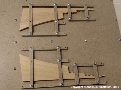
After a whole Sunday of work I got the milled halves and was very frustrated. The technique which has worked at the fore deadwood perfectly did not work on the after deadwood.
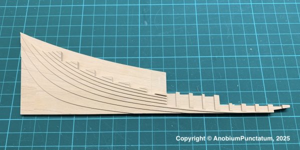

On the pictures you can see the vertical steps which I did not want tor create. But the biggest problem where I could not find a solution is that both halves have now a different thickness. One part is to thinn and I do not have enough wood to equalize the steps. The other part is a little bit to thick. Also the middle glueing lis is broken.
At the end I decided that I will not use for my model and fully redo the parts. In the same time I plan to change the process. I will only glue the two bottom and two top parts together. Then I plan to mill the parts but every part as his own to avoid the problem with the thickness. At the end I will glue the 4 parts together to build the whole deadwood.
Please cross your fingers that I will have more success with the next try and can show you than a real update of my build.
After finishing the fore deadwood I was really optimistic that I can simplify the steps of milling the parts of my after deadwood. So I prepared the files to cut the different steps in the deadwood. First I fixed the prepared deadwood halves on a board than I started the milling process.

After a whole Sunday of work I got the milled halves and was very frustrated. The technique which has worked at the fore deadwood perfectly did not work on the after deadwood.


On the pictures you can see the vertical steps which I did not want tor create. But the biggest problem where I could not find a solution is that both halves have now a different thickness. One part is to thinn and I do not have enough wood to equalize the steps. The other part is a little bit to thick. Also the middle glueing lis is broken.
At the end I decided that I will not use for my model and fully redo the parts. In the same time I plan to change the process. I will only glue the two bottom and two top parts together. Then I plan to mill the parts but every part as his own to avoid the problem with the thickness. At the end I will glue the 4 parts together to build the whole deadwood.
Please cross your fingers that I will have more success with the next try and can show you than a real update of my build.
It would seem every approach to modeling has its unique challenges... Fingers crossed for you!


