HMS ALERT 1777 - 1:48 POF - Trident Model, By Ronco

Joined
Apr 7, 2020
Messages
11
Points
58

Hi All,
I received the kit last monday, after waiting for long time my turn (I added to the list on Oct, 15 2020), the shipment was very fast at least, it took just 1 week from China to italy.
This is my first POF, so I am 100% sura I will need yuor help.
I spent these weeks reading the KIT manual, that it confused me, and reading the forum where I found a lot of helpful information.
I gonna cleaning the wood dust as first step.
 
Good Luck , its a lot of fun! Take your time and follow the instructions closely. It all makes sense one start to actualllyput it together. Use the templates provided. They are a great help.
 
Many thanks for starting your build log, Ronco76. We have a plethora of information here, take your time to familiarize yourself with various builds. But, If you need help, just post your question here. ;)

Good luck!
 
I am looking forward to see your work on the Alert - Have fun - and we will follow your progress
 
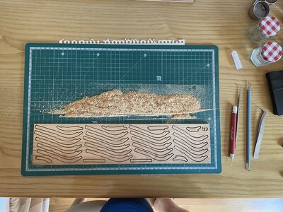
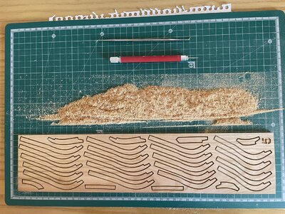
I have finished removing the saw dust from the board, I have also written an inventory (excel document). to find easier the parts when I will start assembling them.

I think there a few mistakes, in the manual there is a cross on A63-3-table 4, but it is physically present on the board and should be A63-1. In table 12 there are 4 71-1, but those circled in red should be 71-2.

Immagine1.jpg
Immagine2.jpg
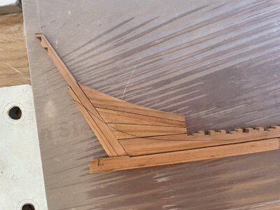
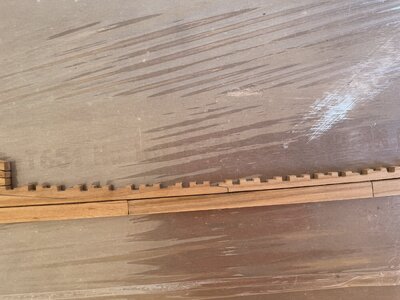
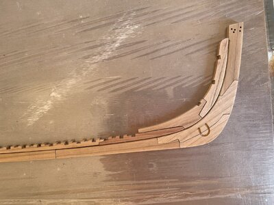
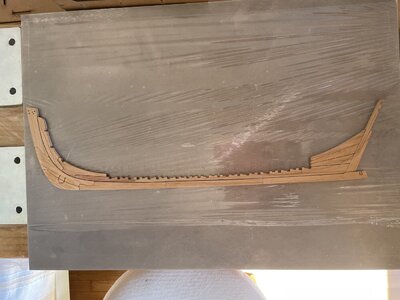
I start assembling the berth - building JIG soon.
 
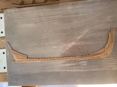
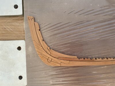
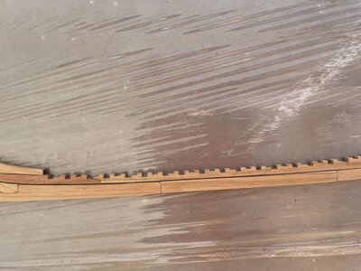
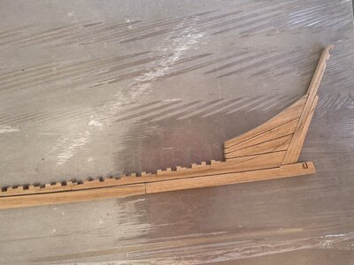
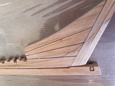
I'm gonna start assembling the keel in the next days, I have some doubt regarding the caulking.
As far as I know it was done into the planking or deck planking, but I saw some of you did it in the keel as well.
I have summarized all the areas in which it was done.

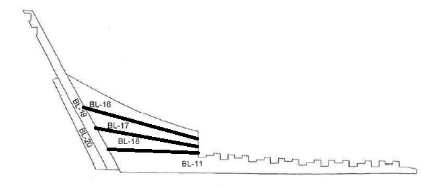
BL16 - BL17
BL17 - BL18
BL18 - BL11

Immagine454672.jpg

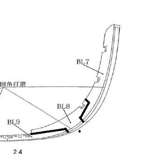
BL7 - BL8
BL8 - BL9
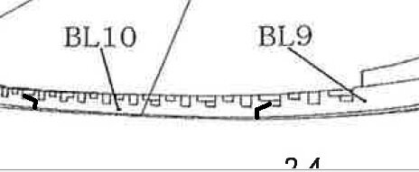
BL9 - BL10
BL10 - BL11

Immagine674820.jpg Immagine5657575803.jpg

BL1 - BL2
BL2 - BL3
BL3 - BL4
BL4 - BL5
BL5 - BL6

Immagine757575757.jpg
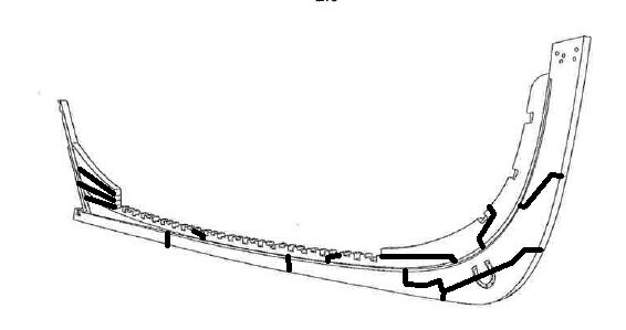
The black lines are where to caulk.
The caulking was done to prevent water from entering the hold, so for me it is strange to do it, for example, on the outside of the keel (BL1 - BL2, BL2 - BL3, BL3 - BL4, BL4 - BL5, BL5 - BL6)
.
 
The black lines are where to caulk.
The caulking was done to prevent water from entering the hold, so for me it is strange to do it, for example, on the outside of the keel (BL1 - BL2, BL2 - BL3, BL3 - BL4, BL4 - BL5, BL5 - BL6)
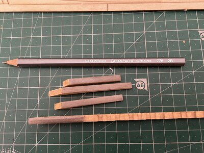
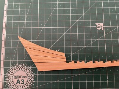
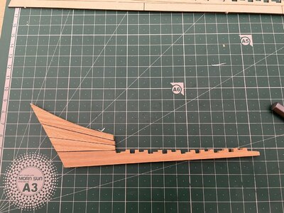
Hello, Ronko. You are correct about the caulking statement. On my model, I made it just to represent the different timber boards making the deadwood and other keel and Stem\Sterm pieces more visible in assembly. I used a pencil to mark the edges. ;)
 
I like the idea to mark/represent the different part of the keel, I was wondering what is better to use (pencil, black glue) to remain as close as possible to reality.
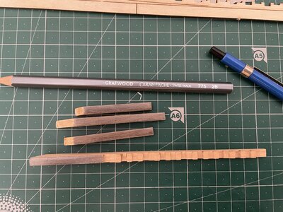
I think I use a 2B or 5B pencil, the black glue seems a bit too "aggressive".
 
The joint marks are mostly for visual appeal, more than real life use.

I have used hard pencil and rubbed both sides of joint and got good results that were not too bold.

I will be watching your build as well!

One day I may get to mine.

Kurt
 
I like the idea to mark/represent the different part of the keel, I was wondering what is better to use (pencil, black glue) to remain as close as possible to reality.
I think I use a 2B or 5B pencil, the black glue seems a bit too "aggressive".
In reality on the real ships, there was usually not used any caulking between the elements of a keel.
Modelers are doing this sometimes only to visualize more the parts.
If you decide to do it, you should take the correctness of the joints into account.
If the joints are not very accurate you will have some gaps between the elements of the keel, which will be filled with the black glue -> and than you have blackened the whole gap -> often this is too aggressive, like you wrote.
Especially on the keel elements, you should be very accurate in the joints if you immitate the caulking. In my personal subjective opinion, it is often better not to do it, but as often it is a question of taste.
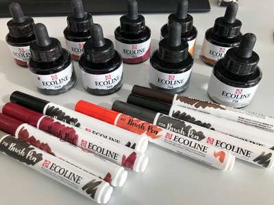
For caulking I made in principle very good experiences with using the brush pens from ecoline - here you can decise if you "paint" only one side or both of the connecting parts
ecoline.jpg

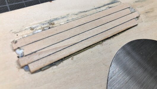
Here a test of deck planking with both sides painted with acoline (after scraping)
IMG-6329.jpg
 
Hi Guys,
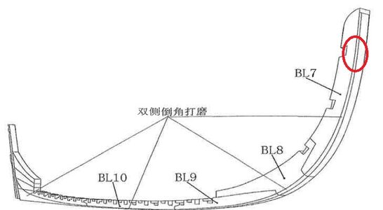
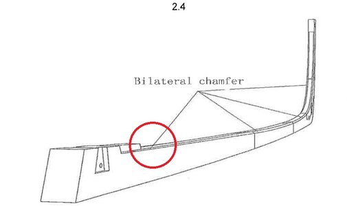
Could someone advise me how many mm has to be this chamfering? Immagine1.jpg

I suppose in this area has to be flat and then increase up to 45° (in the middle of the ship), and keep this angle up to the bow.

Immagine2.jpg
 
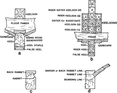
First take a look at this document, especially on sketch G-4 where the so called rabbet line is shown. Here you see the principle connection


oxfordhb-9780199336005-graphic206-full.gif

Figure G-4. Principal timbers; sectional views: (a) a popular arrangement for small and medium-sized craft; (b) a typical arrangement of principal timbers for large vessels, this for an early-twentieth-century four-masted schooner with a 200-ft-long double keel; (c) the designations of keel and post rabbet surfaces; and (d) the designations of the lines formed by the junction of the rabbet and garboard surfaces.

Or this page:


and also this pdf attached will help describing the rabbet

I am usually take a typical plank of my model and try to find out directly at the keel how the plank will touch the keel and cut (with a chisel) approximately.
If you plan to completely plank the model the rabbet line is not visible any more, only the bearding line. So this line is most important - personally speaken: Nobody cares about inside, which will be completely covered with the plank, means if you make the champfer 30° or 45° - the visible bearding line sould be as exact as possible
 

Attachments

  • Planking Project.pdf
    1.9 MB · Views: 43
Back
Top